IDL stands for Igomatzu Dream Laboratory. Despite the “Japanese” name, our company...
Many breakthrough technologies in electroacoustics have their roots in aviation. You don’t need to look far for examples: composite sandwich diffusers, magnesium and titanium domes of high-frequency speakers, fiberglass and carbon fiber... By the way, there were and are engineers with aviation education in the AZ editorial office. This is not without reason - aviation and acoustics have a common desire for excellence.
“We were born to make a fairy tale come true...”
(“Airmarsh”, A. Khait)
Igor Matsyuk (IgoMatzu) has been interested in electronics, acoustics and aircraft modeling since childhood. Then he received a first-class engineering education at the Kharkov Aviation Institute (KhAI), but he did not have to work in his specialty - perestroika, lack of work, equipment repair and custom-made acoustics. Then I worked at , the first independent installation in car audio, my participation in competitions, and judging. And then the realization of the imperfections of traditional dynamic drivers came, and the idea was born to create a set of isodynamic drivers for three-four-way audio systems. Universal emitters, suitable for use both in the car and at home... A fairy tale, you say. But it is becoming reality before our eyes.
A little about the concepts. The main difference between an “isodynamic driver” and a traditional dynamic head is that the driving force is not applied to any one point or section of the diffuser, but is evenly distributed over its entire area. As a result, the piston action zone covers the entire operating frequency range, and nonlinear distortions are significantly reduced. The voice coil is made in the form of a flat spiral applied to a membrane made of polymer film, as a result the mass of the moving system is minimal, and the inductance of the voice coil is practically absent. This is the main thing, everything else is a consequence of design and technology.
In isodynamic emitters, the magnet is located on the lower side of the membrane; in an orthodynamic system, magnets are located on both sides of the membrane, this increases the linearity and sensitivity of the emitter. An acoustically transparent magnetic core (steel mesh) becomes a necessary element.
The lack of powerful and compact magnets has long prevented the spread of such emitters. But with the advent of neodymium magnets, the problem was solved.
Currently, the series includes four types of emitters: broadband/mid-frequency FR-104100 / MR-104100 (differing in acoustic design) and two high-frequency drivers - HDT-8580 and HDT-6562. The basis of all converter membranes is the Russian analogue of Kapton - polyimide film. Not polyamide, but polyimide, these are different classes of materials! The material of the tweeter tracks is aluminum. For mid-frequency speakers - copper. Case material – duralumin. The coating is matte epoxy powder paint with a slight shagreen texture. All magnetic systems are optimized for the task at hand. The emitters are intended for professional installation, so they are not supplied with mounting parts - they can be purchased separately.
DESIGN
IDL FR-104100
This is a broadband option designed specifically for car audio. In the mid-frequency there is an aperture body - it improves the radiation pattern, but limits the range of operating frequencies from above. An acoustic damper is installed on the back side of the membrane
Author's drawing with all dimensions. Product weight 750 - 760 g
IDL HDT-8580
The emitter is designed for two- and three-plane systems
The design is in many ways similar to the 104100, but noticeably more compact. Weight 430 - 440 g
IDL HDT-6562
The emitter is designed for three- and four-way systems. Flexible conductors instead of terminals made it possible to reduce dimensions
The weight also became smaller, 325 - 335 g
Room acoustics (geometric theory)Geometric (ray) theory
Basic provisions. The geometric (ray) theory of acoustic processes in rooms is based on the laws of geometric optics. The movement of sound waves is considered similar to the movement of light rays. In accordance with the laws of geometric optics, when reflected from mirror surfaces, the angle of reflection b is equal to the angle of incidence a, and the incident and reflected rays lie in the same plane. This is true if the dimensions of the reflecting surfaces are much larger than the wavelength, and the dimensions of the surface irregularities are much smaller than the wavelength.
The nature of reflection depends on the shape of the reflecting surface. When reflected from a flat surface (Fig. 7, a), an imaginary source I' appears, the location of which is felt by ear, just as the eye sees an imaginary light source in a mirror. Reflection from a concave surface (Fig. 7, b) leads to focusing of the rays at point I'. Convex surfaces (columns, pilasters, large moldings, chandeliers) disperse sound (Fig. 7, c).
Rice. 7
The role of initial reflections. The delay of reflected sound waves is important for auditory perception. The sound emitted by the source reaches an obstacle (for example, a wall) and is reflected from it. The process is repeated many times with a loss of energy at each reflection. The first delayed pulses, as a rule, arrive at the listeners' seats (or at the microphone location) after reflection from the ceiling and walls of the hall (studio).
Due to the inertia of hearing, a person has the ability to preserve (integrate) auditory sensations, to combine them into a general impression, if they last no more than 50 ms (more precisely 48 ms). Therefore, the useful sound that reinforces the original sound includes all waves that reach the ear within 50 ms after the original sound. A delay of 50 ms corresponds to a path difference of 17 m. Concentrated sounds arriving later are perceived as an echo. Reflections from obstacles that fall within a specified period of time are useful and desirable, since they increase the sensation of volume by values reaching 5 - 6 dB, improve sound quality, giving the sound “liveness,” “plasticity,” and “volume.” These are the aesthetic assessments of musicians.
Studies of initial reflections using the acoustic modeling method were carried out at the Scientific Research Film and Photo Institute (NIKFI) under the leadership of A. I. Kacherovich. The influence of shape, volume, linear dimensions, and placement of sound-absorbing materials on the sound quality of speech and music was studied. Interesting results were obtained.
The direction of arrival of the initial reflections plays a significant role. If delayed signals, i.e. Since all early reflections arrive to the listener from the same direction as the direct signal, the ear can hardly discern any difference in sound quality compared to the sound of direct sound alone. The impression arises of a “flat” sound, devoid of volume. Meanwhile, even the arrival of only three delayed signals in different directions, despite the absence of a reverberation process, creates a spatial sound effect. The sound quality depends on the directions from which and in what sequence the delayed sounds come. If the first reflection comes from the front side, the sound deteriorates, and if it comes from the back side, it deteriorates sharply.
The delay time of the initial reflections relative to the moment of arrival of direct sound and relative to each other is very significant. The delay durations should be different for best sounding of speech and music. Good speech intelligibility is achieved if the first delayed signal arrives no later than 10 - 15 ms after the direct signal, and all three must occupy a time interval of 25 - 35 ms. When playing music, the best sense of spatiality and “transparency” is achieved if the first reflection reaches the listener no earlier than 20 ms and no later than 30 ms after the direct signal. All three delayed signals should be located in the time interval of 45 - 70 ms. The best spatial effect is achieved if the levels of the delayed initial signals differ slightly from each other and from the level of the direct signal.
When connecting the rest of the echo to the structure of the initial reflections (first, second, third), the most favorable sound is obtained when the second part of the process begins after all discrete reflections. Connecting the reverberation process (echo) immediately after the direct signal worsens the sound quality.
By ensuring the optimal structure of the initial (early) reflections, the sound of music remains good even with a significant (10 - 15%) deviation of the reverberation time from the recommended one. Achieving optimal delay of reflected signals in relation to direct sound puts forward a requirement for a minimum volume of the room, which is not recommended to be violated. Meanwhile, when designing a room, its dimensions are chosen based on the given capacity, i.e. They solve the problem purely economically, which is wrong. Even in a small concert hall, the optimal structure of early reflections can be obtained only at a given height and width of the hall in front of the stage, less than which it is impossible to go down. It is known, for example, that the sound of a symphony orchestra in a hall with a low ceiling is significantly worse than in a hall with a high ceiling.
The results obtained made it possible to develop recommendations regarding the delay time and the size of the hall. It was taken into account that the first delayed signal, as a rule, comes from the ceiling, the second - from the side walls, and the third - from the back wall of the hall. Different requirements for the delay time of initial reflections are explained by the characteristics of speech and musical sounds and the difference in the acoustic problems being solved.
| Dt2, ms | Dt3, ms | ||
| Speech | 10 — 15 | 15 — 22 | 25 — 45 |
| Music | 20 — 30 | 35 — 50 | 50 — 70 |
To achieve good speech intelligibility, the delays must be relatively small. When playing music, it is necessary to emphasize the melodic beginning; to ensure the unity of sounds, a longer delay time of the initial reflections is necessary. This leads to the recommended dimensions of concert halls: height and width of at least 9 and 18.5 m, respectively, and no more (at the portal) 9 and 25 m.
It is possible to increase the height and width of the hall to some extent only at a distance from the stage portal (stage) exceeding approximately 1/4 - 1/3 of the total length of the hall: height up to 10.5 m, width up to 30 m. The length of the hall is chosen taking into account the need receive sufficient direct sound energy at the most distant listening positions. Based on this circumstance, it is recommended to choose a hall length of no more than 40 m along the ground floor, and 46 m along the balcony.
The table provides information about the geometry of some halls, the acoustic qualities of which are considered good (n is the capacity of the hall, lп is the greatest distance of the listener from the stage in the stalls, lb is the same on the balcony, Dt1 is the delay time of the first reflection).
| Hall | n, people | lп, m | lb, m | Dt1, ms |
| Column Hall of the House of Unions, Moscow | — | — | — | 24 — 28 |
| Great Hall of the Moscow Conservatory | 1900 | 29 | 47 | 21 — 26 |
| Small Hall of the Moscow Conservatory | 400 | 21 | 25 | 21 — 26 |
| Hall of the Academic Chapel, St. Petersburg | — | — | — | 25 — 30 |
| Concert Hall, Boston | 2630 | 40 | 45 | — |
| Concert Hall, New York | 2700 | 34 | 45 | — |
| Concert Hall, Salzburg | 2700 | 34 | 45 | — |
| Concert Hall, Caracas | 2000 | 28 | 35 | 30 |
Thus, the minimum dimensions of a room for playing music (height and width) are not related to its capacity, but are determined by the necessary structure of the initial reflections. Even if the room is intended for performing music in the absence of listeners (recording studio, sound broadcasting studio, music recording studio, film studio listening room), its size should be determined only by the sound quality of the music. “Saving” on these sizes means significantly worsening the sound quality.
Historical examples. From the religious and spectacular buildings that have survived to this day, it is clear that the main provisions of the ray theory were known to the ancient builders and that these provisions were strictly observed. The dimensions of Greek and Roman open-air theaters were chosen to make the most of the energy of reflected waves.
The theaters contained three main parts:
- A stage (shena) 3.5 - 4 m deep in Greece and 6 - 8 m in Rome, on which theatrical action was performed;
- The area in front of the stage - the orchestra (orhestra literally “place of dancing”), on which the choir was located and the dancers performed;
- Seats rising in steps around the orchestra, forming the so-called amphitheater (from the Greek words amphi - “on both sides”, “around” and theatron - “place of spectacles”).
The sounds from the performers reached the audience located in the amphitheater through direct path 1, as well as after reflections from the surface of the orchestra (beam 2) and wall 3 located behind the stage (Fig. 9, a). The plane of the orchestra was covered with highly reflective material. As Vitruvius pointed out, the height of wall 3 should be chosen equal to the height of parapet 4, which enclosed the top row of the amphitheater, “to improve acoustics.” Apparently, the point was to prevent excessive dissipation of sound energy in space. The depth of the stage in Greek theaters was made small so that rays 5 reflected from the back wall were not too late in relation to the direct ray 1 and did not impair the intelligibility of the actors' speech. Part of the sound energy, reflected from walls 3 and 4, went upward. In modern indoor theater halls, this energy is reflected down the ceiling and increases the intensity of sound in the audience seats. The orchestra hosted dancing and a choir that repeated the actors’ lines, i.e. performing the task of sound amplification. When the choir is located at point 1, sound rays, reflected from wall 3 (Fig. 9, b), come to the viewer with a large time delay, causing an echo. To reduce this shortcoming in Roman theaters, the choir began to be located closer to the stage, at point 2. Then, reflections from the stage began to be used to direct energy towards the audience (its height in Roman theaters reached 3.5 m), and the dancers occupied the vacant part of the orchestra. In modern theaters there are musicians in front of the stage, and the name of the stage they occupy is transferred to them.
Rice. 9
A special role in enhancing and enriching the sound was played by the so-called “harmonics” - systems of resonators in the form of bronze cylindrical vessels and clay amphorae jugs. They were located in wall niches behind the spectator seats and under the benches. The Greeks believed that for the euphony of speech and music, resonators should be selected or tuned according to the tones of musical scales: enharmonic, chromatic and diatonic.
- The first system, according to their creators, imparted solemnity and severity to the sounds;
- The second, thanks to the “crowding” notes, is the sophistication and tenderness of the sound;
- Third, due to the consonance of intervals, the naturalness of musical performance.
It is obvious that ancient architects, when constructing theaters, looked for and found technical ways to convey to spectators and listeners not only semantic, but also artistic (aesthetic) information, and sought to enrich the musical sound.
Theater and concert halls of the 18th and 19th centuries were distinguished by their rational shape and wisely chosen dimensions. A number of acoustically good theater and concert halls were built in different countries in the 20th century.
Bad decisions. It would seem that the experience accumulated over thousands of years should be used by modern architects and builders. Meanwhile, examples of unsatisfactory acoustic solutions are multiplying, for example, the construction of halls that are round or elliptical in shape (the Colosseum cinema in St. Petersburg, the Tchaikovsky concert hall in Moscow, etc.). In them, zones of focusing of reflected rays and zones are formed into which the reflected rays either do not fall or fall with a large time delay. In a hall that is circular in plan (Fig. 10 on the right), ray 1, tangent to the wall, remains in the zone close to the wall during subsequent reflections. Rays 2, propagating approximately in the diametrical direction, form, after reflection, a virtual image of the source I', in which the sound intensity, as in the annular zone near the wall, is increased. Halls with a flat ceiling and a low stage portal are unsatisfactory (Fig. 11, a). The ABC zone turns out to be a kind of trap for a significant part of the energy emitted by the sound source. Only the DE zone produces useful reflections, but they only reach the distant part of the EC hall. Preferable designs are those with a diffuse ceiling (Fig. 11, b), an acoustic shell and a canopy (Fig. 11, c).
Fig 11
The famous Albert Hall in London, 56 m wide and 39 m high, was acoustically unsatisfactory. Due to the unusually high height of the hall, the path difference between direct sound and sounds reflected from the ceiling reached 60 m, which resulted in a delay of almost 200 ms. The center of curvature of the concave ceiling was in the area occupied by the listeners, which generated a strong echo.
An example of an unsuccessful acoustic solution is the Great Hall of the Central Theater of the Russian Army (CTRA). The main disadvantages of the hall: the large width, equal to 42 m in the middle of the hall, and the excessively high ceiling - at the portal it is 18 m above the stage plank (Fig. 12). Reflections from the side walls do not arrive in the central part of the hall, and the first reflections from the ceiling arrive in the middle of the stalls with a delay of more than 35 ms. As a result, speech intelligibility in the stalls is low, despite the proximity of the actors to the audience. The shape of the rear wall of the hall and the balcony parapet is part of a circle, the center of which is located on the proscenium at point O. Sounds reflected from the rear wall and the balcony parapet return to the same point and are heard as a strong echo, because the delay exceeds 50 ms. When the actor moves to point I, the conjugate focuses I' and I shift to the ground. As a result, an echo appears in the front rows of the stalls.
Once upon a time, the MTUSI assembly hall had good acoustics, where symphony concerts were even held and broadcast on the radio. Acoustic conditions have deteriorated significantly after the hall was redecorated. The design of the balcony fencing was changed, in the depth of which a reflective shield was placed. Strong reflections from the parapet and shield worsened the sound in the stalls. Due to large delays, speech intelligibility decreased.
An example of an unsuccessful acoustic solution is the Central Concert Hall of the Rossiya Hotel in Moscow. The square shape of the hall led to a depletion of the spectrum of natural frequencies, the low ceiling creates a small delay in the first reflections, and the large width of the hall means that reflections from the walls do not fall into the first half of the stalls. Three times they tried to improve the sound by replacing sound-absorbing materials and placing them in the hall. However, it was not possible to compensate for the obviously unsuccessful original shape of the hall.
Rice. 12
Even in rooms with correctly chosen shapes and linear dimensions, the proportions of which are close to the “golden ratio”, sound defects are discovered, the elimination of which takes a lot of time, effort and money. Sound and television broadcasting studios need careful preparation for normal operation. An example is the complex of works to prepare studio N5 of the State House of Radio Broadcasting and Sound Recording (GDRZ). The studio is intended for the performance of works of large forms with the participation of a symphony orchestra and choir in the presence of listeners. Its linear dimensions (29.8 x 20.5 x 14 m) almost correspond to the “golden ratio”; the estimated reverberation time at mid frequencies is 2.3 s. Due to the large height and width, the arrival time of the initial reflections is not optimal. To reduce the length of the paths of reflected rays, reflective panels were installed above the orchestra location and on the side walls. It took several times to change the position of the panels and reduce the area of sound-absorbing structures before musicians and sound engineers recognized the sound quality as good. This example shows how subtle and meticulous the acoustic tuning of rooms is.
There are halls designed for a small number of listeners, correspondingly small in area and low in height. Their authors apparently believed that given the small size of the hall, “everything will be clearly audible.” In fact, in such halls, a dense structure of initial reflections is formed at the listening seats. Because of this, with a short reverberation time, the sound turns out to be “flat”, similar to the sound in the open air, and with a long reverberation time, the “transparency” of the sound is lost, and subsequent musical sounds begin to be masked by the previous ones.
Also, for the most part, the so-called assembly halls are unsatisfactory. They are intended for meetings, i.e. for the sound of speech. Low ceilings, smooth parallel walls, devoid of acoustic finishing give rise to suboptimal initial reflections. Attempts to hold concerts there do not bring success. The music doesn't sound good on them. The worst thing is that concerts in such halls spoil the audience. The acoustics of the so-called “concert and sports” halls are below any criticism.
In our country, the “fight against architectural excesses” has caused great harm to the quality of theater and concert halls. All sound-diffusing and sound-absorbing structures, and even the soft upholstery of seats, designed to serve as the equivalent of absent spectators, were declared “excesses.” As a result, the listening seats have a poor structure of initial reflections, low diffuseness, and when partially filled, excessive “boominess”.
The best halls. The Column Hall of the House of Unions, the Big and Small Halls of the Moscow Conservatory, the Big Hall of the St. Petersburg Philharmonic and some other halls of the old building remain unsurpassed in sound quality.
The achievements of domestic architectural acoustics include the auditoriums of the Children's Musical Theater, the Theater named after. Evg. Vakhtangov, Moscow Drama Theater named after. A.S. Pushkin, the ZIL Palace of Culture, the studio of the State House of Sound Recording, the sound recording studio and the Mosfilm listening room. During their design and construction, the provisions and recommendations of domestic and foreign acousticians were taken into account.
In these halls, the requirements of geometric acoustics are met: the shape and dimensions are rationally chosen, which ensures a high degree of field diffusion and optimization of the delay times of the initial reflections. In each specific case, its own architectural and planning solutions are selected. The relatively small width halls are shaped like a rectangular parallelepiped. These are the Great and Small Halls of the Moscow Conservatory, the Great Hall of the Moscow House of Scientists. With a small width, the number of reflections arriving at the listening positions quickly increases over time and in the final part of the reverberation process is so large that it ensures good field diffusion. In large halls (Column Hall of the House of Unions, Great Hall of the St. Petersburg Philharmonic) sound-diffusing structures in the form of a series of columns were introduced. In modern large-capacity halls, good sound dispersion is achieved by dividing the walls and ceiling and installing large dissipative surfaces on the walls.
The material with which the walls and ceiling are finished is important. The best is wood. The sound of music in halls decorated with wood has a beautiful timbre. On the contrary, reinforced concrete structures, especially thin ones, and plaster on a chain-link mesh are completely contraindicated. Sounds reflected from these surfaces have an unpleasant “metallic” tint.
Conclusion
The three considered theories explain the acoustic processes occurring in rooms from different angles. Of these, only one - statistical - makes it possible to determine a numerically important quantity characterizing the acoustic properties of a room - reverberation time. You just need to be conscious and critical of the resulting numerical estimate and understand that in most cases, especially when considering large premises, it is indicative in nature.
According to modern views, it is customary to divide the process of echo, reverberation into two parts: initial, relatively rare delayed impulses, and a sequence of impulses that becomes more dense over time. The first part of the echo is assessed from the standpoint of geometric (ray) theory, the second - from the standpoint of statistical theory.
Geometric theory is more applicable to the analysis of acoustic processes in large rooms - concert and theater halls, large studios. The optimal dimensions of the hall (studio) are determined based on the analysis of initial reflections. When designing large rooms, calculating the reverberation time can give a result that differs significantly from the real one, and most importantly, this value does not allow us to fully assess the acoustic quality of the room. In such an assessment, the initial reflections play a major role. The correct timing of the initial reflections ensures high sound quality even when the reverberation time is not optimal.
Statistical and wave theories are especially applicable to relatively small rooms, such as audio broadcast studios and auditoriums for various purposes. The results of these theories seem to complement each other. The first makes it possible to estimate the reverberation time, the second - to calculate the spectrum of natural (resonant) frequencies, adjust the dimensions of the room so that the spectrum of natural frequencies in the lower frequencies is more uniform.
It would be very interesting and important to combine the provisions of acoustic theories, to create a unified theory that would explain from a general perspective the complex acoustic processes occurring in rooms of different purposes, of different shapes and different sizes. But until this is achieved, it remains to consciously use existing theories and achieve the best solutions with their help.
We recommend that you refer to the sources listed in the bibliography, where you can find a lot of interesting and useful things for yourself.
Literature
- Acoustics: Handbook / ed. M.A. Sapozhkova. - M.: Radio and Communications, 1989.
- Brekhovskikh L.M. Wave propagation in layered media. - M.-L.: Publishing house. USSR Academy of Sciences, 1958.
- Drazen I.G. Electroacoustics course, part 1. - M.: Svyazradioizdat, 1938.
- Drazen I.G. Electroacoustics and sound broadcasting. - M.: Svyazizdat, 1951.
- Emelyanov E.D. Sound system for theaters and concert halls. - M.: Art, 1989.
- Contury L. Acoustics in construction. - M.: Stroyizdat, I960.
- Makrinenko L.I. Acoustics of public premises. - M.: Stroyizdat, 1986.
- Morse F. Vibrations and sound. - M.-L.: Gostekhizdat, 1949.
- Sapozhkov M.A. Soundproofing of premises. - M.: Communication, 1979.
- Skuchik E. Fundamentals of acoustics. - M.: Publishing house. foreign lit., 1959.
- Strutt J.W. (Lord Rayleigh). Theory of sound. - M.: GITTL, 1955.
- Furduev V.V. Electroacoustics. - M.-L.: OGIZ-GITTLE. 1948.
- Furduev V.V. Acoustic fundamentals of broadcasting. - M.: Svyazizdat, 1960.
- Furduev V.V. Modeling in architectural acoustics // Film and television technology, 1966. N 10
Address of the site administration
DID NOT FIND WHAT YOU WAS LOOKING FOR? GOOGLE:
| CUSTOM SEARCH STRING |
MEASUREMENTS
IDL FR-104100
This is the only emitter whose Z-characteristic has a familiar appearance. Failure at 400 Hz – operation of a resonant chamber with an acoustic damper
Everything else is at least unusual. The electrical quality factor is higher than the mechanical one, the inductance is insignificant.
| FS, Hz | 266,5 |
| RE, Ohm | 5,0 |
| QTS | 1,86 |
| QMS | 2,98 |
| QES | 4,98 |
| L10kHz, mH | 0,0329 |
The drop in frequency response below 300 Hz is natural; reducing the resonance frequency given the existing dimensions is problematic. A small hump in the mid-frequency region can be easily suppressed by choosing a low-pass filter cutoff frequency of the order of 2.5-3 kHz - the sound pressure cutoff frequency will be in the region of 4-6 kHz. Above this frequency, the directionality of the radiation is clearly pronounced, but along the axis and 20 kHz is not the limit. With a focus on the listener and a slight correction of the frequency response, you can even do without a tweeter, a dream for fans of wide receivers.
However, from below, the band of reproduced frequencies is determined by the permissible level of distortion arising due to the small linear stroke of the diaphragm. From the graph taken at an average sound pressure of 90 dB/1m, it follows that the high-pass filter cutoff frequency must be chosen not lower than 500 Hz and at least second order
IDL HDT-8580
Traces of resonance can still be found on this z-characteristic. And traces of inductance were found only by a data analysis program
| FS, Hz | 2447,5 |
| RE, Ohm | 5,0 |
| QTS | 1,09 |
| QMS | 1,19 |
| QES | 13,01 |
| L1kHz, mH | 0,021 |
| L10kHz, mH | 0,003 |
The angular characteristics are excellent; you can forget about laser orientation and shamanic dances. The sensitivity is high - an average of 95 dB/W/m, distortion was measured at the same level. Obviously, the operating range limit must be chosen at least 3 kHz
IDL HDT-6562
And here you can’t even see traces of resonance with a magnifying glass... But the program knows its stuff
| FS, Hz | 2453,5 |
| RE, Ohm | 7,8 |
| QTS | 0,15 |
| QMS | 0,16 |
| QES | 1,95 |
| L1kHz, mH | 0,014 |
| L10kHz, mH | 0,003 |
Due to strong acoustic damping, the mechanical, and therefore the overall quality factor, is low - to the point of complete amazement. The increased impedance makes sensitivity matching easier and is useful for systems with passive crossovers.
The characteristics were taken at the same input voltage as for the HDT-8580, the output is naturally lower due to the higher impedance. The axial frequency response is excellent, distortion at 90dB/W/m is low. Recommended cutoff frequency – 2 kHz and above
Nmax=20lg(pproct/po);
where po = 2-10-5 Pa is the hearing threshold at a frequency of 1000 Hz.
For a sinusoidal signal, the number of reference points must be at least 7 (every 1/6 octave), for one-third octave filters - at least 3. The unevenness of the frequency response is determined in the nominal and operating frequency ranges.
The directional characteristic is obtained in an anechoic chamber or in the open air by rotating the speaker relative to a stationary measuring microphone at a distance of 1 m through 5-10° in the range of 0-360°. The width of the directivity characteristic is determined from the graph at the level of 0.dB). Directivity is determined at one or more frequencies or at mid-frequencies of one-third octave filters when making measurements on noise signals.
As follows from the above, for a qualified assessment of the parameters of an AS or AO, it is necessary to carry out a significant amount of metrological work and calculations. Considering that to assess the effectiveness of acoustic design, it is necessary to measure the electroacoustic efficiency:
PERSONAL EXPERIENCE
The sound of the wideband FR-104100 impressed with its openness and excellent impulse response. The reproduction of the attack of plucked instruments is unusually realistic, all the after-sounds and atmosphere of the recording are perfectly conveyed. And all the “jambs” too. The high-frequency speakers were not heard on the musical material; on the test signals it is worth noting the excellent frequency range - the upper limit exceeds the capabilities of average hearing. For hi-res you can't think of anything better.
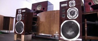
Acoustics. Orthodynamic emitters
Hi all. I want to tell you a little about non-standard emitters. Orthodynamic membranes were invented, like many good things, in Japan and for a long time were used in many models of Yamaha, Audio Technica, etc. The structure of such speakers is both simple and complex. In essence, they are two round magnets and a membrane between them, which form a kind of sandwich.
If you wish, I ask under cat.
The trick of this technology is that they are magnetized differently, in different parts of the magnet. In concentric circles, similar to the annual rings of trees, the areas of different poles cover the entire magnet, diverging from the center to the edges. In the illustration, the south is marked in red, so you can roughly imagine how it all is located. Now let's move on to the membrane. Unlike a dynamic system, this is not a diffuser glued to a magnetic coil, but a thin membrane on which a conductive path is applied in a spiral.
The tracks were applied either by etching a previously applied layer of metal foil, or by gluing a ready-made spiral onto a Mylar membrane. Lavsan, with a film thickness of 5-8 µM, had an extremely low weight, comparable to the weight of air vibrating by the film. When current was applied, the spiral generated an electromagnetic field, which began to interact with the constant magnetic field of the magnet pancakes, and as a result, it began to vibrate and generate sound. The emitter itself looks like this:
This technology has one main advantage: due to the extremely low mass of the film membrane, the level of distortion is very low and close to ideal. This is already Hi-Fi class. Orthodynamics was used almost exclusively in headphones, and was actually created for them, as a modification of the earlier technology of isodynamic drivers. The operating principle of both technologies is fully described in the corresponding patent.
Now I want to argue why I classify headphones created using this technology as Hi-Fi. — Orthodynamic headphones sound very accurate and true. There is no senseless lifting of bass and highs, the middle does not sag at all. — Thanks to the low inertia of the membrane, the microdynamics are impressive, all the smallest details of the sound are conveyed very well. — The power of the headphones is very high (to be honest, it is excessive at maximum power and it is very possible to go deaf).
Like any non-mass technology, it has its own subtleties. Nuance 1.
Such headphones almost certainly require a special headphone amplifier.
Without it, they will also sound, but “not like that.” Point 2.
They require warming up.
Seriously, if the headphones haven't been listened to for a month, they will need 5 hours to achieve their ideal sound. For daily listening, 5 minutes of warm-up is enough. Point 3.
The quality of the sound source must be very high, as well as the quality of the recording.
Point 4:
You have to love them.
Point 5.
When listening to modern recordings on these headphones, you need to understand that now music is recorded somewhat differently than it was done 30 years ago.
Music in these headphones will sound completely different. Point 6.
Real gurus achieve the optimal sound for themselves by selecting the optimal amplifier and changing the damping of the headphones.
Point 7.
Most headphones do not have deep, punching low bass. For fans of “brain blowing”, headphones may not bring pleasure. At the same time, there are models that cover the entire range. In general, this is the so-called vintage sound.
The largest number of models were produced in Japan by Yamaha. There was also a wide range of headphones in the USSR. The last headphones produced in the CIS were ECHO N-16-40 C, manufactured in the city of Smela.
The latest models known to me are produced by the Japanese company Fostex.
Links: Russian-language headphone forum + its continuation Current list of headphone models with isodynamic and orthodynamic drivers.
The article was compiled on the personal initiative of my beloved Echo N-16-40, which I dreamed about and asked me not to forget about them. Thank you for your attention.
Z.Y. Previously, I collected a collection of Soviet headphones and sometimes I think about returning to this.
HONEY AND TAR
Objectively, all emitters have only one drawback - a sharp increase in distortion at the lower end of the range, this is a consequence of a small linear displacement of the diaphragm. If you choose the lower frequency limit correctly, you can forget about this. The rest is pure pluses: excellent frequency range, excellent impulse characteristics, high sensitivity, good radiation pattern (by the way, it will also be affected by the shape of the adjacent surface). And the fact that IDL emitters can work in both automotive and home systems makes them truly universal.
Ra = 4 pi*p2r2/ ro*cko,
where p is the acoustic pressure at a distance r, Pa; ro—air density; c is the speed of sound propagation, equal to 340 m/s; ko is the concentration coefficient, which can be taken equal to 1...3 depending on the frequency.
When designing an “ORTHO” type loudspeaker, it should be borne in mind that the electroacoustic parameters listed above largely depend on the dynamic drivers used. If the head, for example, does not reproduce low frequencies, then no housing design can compensate for this shortcoming. This acoustic design does not “spoil” the frequency response of the loudspeaker, and this turns out to be one of the decisive advantages compared to known speaker designs. In the proposed acoustic design, heads with diffusers of round, rectangular or elliptical configuration can be used. By installing two heads on the front panel, you can increase the rated power, radiation resistance, and reduce the unevenness of the frequency response.
LITERATURE: 1. Nosov short circuit in the loudspeaker and overcoming it. - Radio, 2003, No. 1, pp. 14-16. 2. , Sapozhkov on acoustics. - M.: Communication, 1979. 3. Acoustics. Directory. Ed. . - M.: Radio and Communications, 1989. 4. , Lyamin acoustic systems. Reference manual. - Minsk, Belarus, 1996. 5. Nosov approach to the design of sound systems. Collection of proceedings of the X session of the Russian Acoustical Society, volume 2. - M., 2000, p. 177-185. 6. and Applied acoustics. - M.: State. publishing house on radio issues, 1938,0.171,Fig. 27.