Meet the power amplifier based on probably the most famous integrated circuits for UMZCH - LM3886. Initially, I wanted to create a power amplifier that would provide good listening sound at a relatively low price. At the same time, I was interested in the simplicity of the design. It was supposed to be just a final amplifier without a preamplifier or selector, because everything is already controlled from a computer or DVD.
Why did you decide to make an amplifier using the LM3886 chip? Of course, due to the fact that it does not need to be started for a long time - it works immediately, unlike transistor UMZCHs. The choice was TDA7294, LM3875, LM3886, LM4780. We will immediately reject the TDA7294 due to its worse parameters. In the end, the LM3886 was chosen due to its easier heat dissipation from a small area (2 instead of 1 with the same contact surface with the heatsink) and slightly higher power than the LM3875.
Amplifier circuit for 3886
LM3886 circuit diagram of an audio amplifier
It is made using middle-class elements. Panasonic FC capacitors with low ESR (63 V) and WIMA (100 V). Vishay resistors with 1% and 0.1% tolerance. Everything is assembled on a printed textolite board.
LM3886 PCB correct
Everything was done in accordance with the application note from the datasheet (with the exception of the capacitors at the amplifier input - the capacitance was increased to 1 µF).
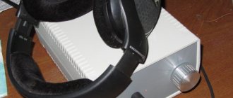
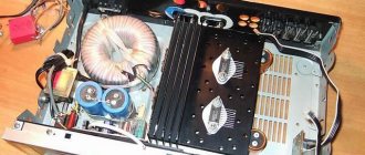
For cooling, 2 radiators from a burnt-out processor with fans were used.
↑ Power supply
The transformer was wound to order. This is due to the fact that a trans with a certain set of windings and dimensions of a certain height was required. The last condition came from the concept of the body, which was invented in advance. Here is the power supply diagram:
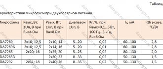
The transformer contains the following windings: - 6.3 V 1 A for filament. — 8 V 0.3 A to obtain stabilized 5 V. Power supply for switching and DAC. — Two windings of 30 V 0.1 A - power supply to the lamp. - Four windings 20 V 3A - power supply LM3886. Thus, two separate rectifiers are used to power the LM3886. Separate for each channel. To power the lamp, a common rectifier is used, but with separate RC circuits.
Also, to indicate that the plug is correctly plugged into the socket, from a phase-zero point of view, an indicator is made on elements R24, R25, D15, D16 and a double-illuminated LED (red and green). Diagram from the Datagor article “Surge filter with control of correct connection to the power supply network for an audio amplifier.”
I would like to say a few words about why, in my opinion, proper connection to the network is necessary. I was taught that the beginning of the winding should be connected to the phase, and the end of the winding to zero. In this case, the zero seems to cover the winding on top and thus additional shielding of the network winding is obtained. I have been convinced of the correctness of this statement more than once, so I try to adhere to this rule.
Since we are talking about the correct connection of the windings, there are a few more comments. Maybe it will be useful to someone. The transformer I use consists of two halves. Each half has two 20 V windings (to power the LM3886). So the question is: how to use these windings? How to connect them correctly? It is clear that the end of one winding is with the beginning of the next.
The question is different: to use two windings on one channel from one half of the transformer or from different ones? Answer: from different ones. It is in this case that there will be less interference. At least that's how it worked out for me. In addition, because I didn’t know where the secondary windings began and where the end was, so I had to experiment. By switching the windings in different ways, I found an option with minimal interference from it. In other words, sometimes it is enough to change the ends of the windings to reduce the hum.
Power supply diagram
2 toroidal transformers 24V 40VA / 28V 120VA were used to power the ULF. Next are 2 diode bridges with 8x MUR860. They are quite fast and durable, but affordable. Then in the PSU there are 4x 6800uF / 50V Nippon (2 pieces per power arm). It was a compromise in terms of price and quality. Additionally, solder thick wires into the tracks to reduce the risk of damage. When the power supply is not loaded, the output is 39V, and when the load is high, the voltage drops to 37V, so this is quite good. Power is supplied through double-insulated cables with a diameter of 2.5 mm.
↑ Fighting the background
When discussing the Corsair on the Internet, there were many complaints about the background of the amplifier. If you collect according to the scheme of the original source, then there really is a background. But you can fight with any background. For myself, I identified the following possible sources of background:
- The background that is provided by the LM3886 and which depends on the power supply of the LM. For the most part, this hum source applies to any amplifier, not just the Corsair. Let's leave this source for last. — Background from incorrect ground layout. The same applies to any amplifier. We'll leave that for later too. — Background from incandescent lamp. — Background from lamp power. We will deal with the last two sources first.
↑ Background from incandescent lamp
Fragment excluded. The full version is available to patrons and full members of the community.
↑ Background from lamp power
Fragment excluded. The full version is available to patrons and full members of the community.
↑ We separate the signal and power grounds
Fragment excluded. The full version is available to patrons and full members of the community.
First launch of ULF
You don't need a case for the first launch. First switching on via current limiter. After inspection and switching on, the amplifier started up immediately. There is practically no constant component at the output. Then connect the old speaker and MP3 player for a test. The amp sounded pretty good. After playing for some time, you can consider the circuit assembled and start working on the box.
The LM3886 is truly great for creating an acoustic amplifier. It may not produce much power, but it has a dynamic sound with good bass and crisp highs. If anything, you can abandon the input resistance and capacitance. As you know, in audio equipment a lot depends on the choice of elements and their quantity. This capacity in the bridge is not really needed. Fans are also not needed because these chips do not get very hot. The quiescent current is so small that without a signal the radiators cool down.
By limiting the number of components, signal paths can be shortened, which is highly desirable for audio. Excellent results are achieved by removing the power supply into a separate case, but it depends on who you prefer. We advise you to clearly separate the power cables and rectifier bridges from the amplifiers. It is important that there is a good quality resistor in the feedback, which is soldered directly to the terminals of the microcircuit.
↑ Printed circuit board
Unfortunately, I don't use special programs. I first draw the boards on paper, or rather on a coordinate tape or “graph paper”. Then I transfer everything to fiberglass. I paint the paths with bitumen varnish or tsapon-varnish. Therefore, I can only provide photographs of the board itself and its wiring diagram on paper. And then it’s up to your creativity.
View of the printed circuit board from the parts side
View of the printed circuit board from the track side. The radiator is already installed for sufficiently effective cooling.
PCB drawing
— The points marked with the letters “A” are intended for connecting with a jumper, if it is not possible to draw a track along the outside of the microcircuit pins, or it is etched. - shaded area - mass (earth). If possible, the wider the better. — the tracks connecting the power input (+ and -), the corresponding pins of the power capacitors and pins “1”, “5” and “4” of the microcircuit are also made as wide as possible. — I don’t recommend making the path connecting the output of microcircuit “3” with the resistor and inductance narrow. As a last resort, you can solder it along its entire length with tinned copper wire. — the board provides the ability to install field-effect transistors KP364, KP303, and, if desired, a resistor (drawn in dotted line) to choose from.
That seems to be all. If you have any questions, write in the comments.
Success in creative work. Sincerely, Yura Zotov.
Housing and assembly
An old tape recorder was used as the housing because it was the right size and had good ventilation. With all the excess removed, it's time to cut out the vent holes in the back and drill out all the screw spots. The ventilation holes were sharpened with a file, but they still didn’t look perfect, so I covered them with pieces of cloth.
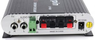
The rear panel has gold-plated banana/speaker terminals that are convenient and look nice. Also on the rear panel is a 6A fuse socket (smaller ones cannot handle the surge in power supply current) and a power switch. The input signal is passed through shielded cables.
The next step is to make the front panel. At first, glue and pieces of plastic began to cover all the extra holes. Then automotive putty. Only the switch and indicator are left. The rest was sanded with sandpaper in the order 80-180-400-600. It turned out to be a pretty good effect.
ULF cooling control - diagram
Two 12V fans powered by a smaller 9V power supply operate in cooling mode. They do not produce noise, but in the future there are plans to change the voltage to an even quieter one.
Contents
- 1 My “Corsair” scheme
- 2 Let's start with UMZCH
- 3 Lamp buffer for 6N23P
- 4 Theory without practice is nothing
- 5 Fighting background 5.1 Background from incandescent lamps
- 5.2 Background from lamp power
- 5.3 Separate the signal and power grounds
Listening
Currently the power amplifier works with old JVC speakers and a CD player from the same company.
- The amplifier sounds very nice. It has clear and dynamic bass, not too much or too little - just right, just right.
- It doesn't drown out the rest of the spectrum, as some designs do, and goes quite low in frequency response.
- The midrange is clear and equally dynamic. High frequencies are clear and not ringing or muffled.
- The guitars are aggressive and the drums don't fade into the background. At high volumes there is virtually no distortion.
I think it sounds much better than the STK UMZCH that I have at home, or several other amplifiers that I heard from friends. The sound is really dynamic and rich. The stereo effect is clearly visible - it’s easy to determine where the guitarist or soloist is.
↑ First start
The amplifier was turned on for the first time with a light bulb in the load (after all, the devil knows).
Oddly enough, the amplifier was silent. It turned out there was trouble with the “mute” chain. Having temporarily replaced the “field switch” with a 15 kOhm resistor, I turned on the amplifier again. Everything worked. Having installed the field-effect transistor in place, I turned it on again - everything works. Well, the situation made me happy. It doesn’t often happen that everything works like this, almost the first time. We turn it off, grab everything and carry it closer to the CD player and speakers. Let's start listening.
↑ Parts used
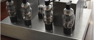
Lamp - 6N23P-EV. Almost all resistors (except for the protection unit) are Kiwame 2 W.
Historically, I use them in tube amplifiers, so I have accumulated a small supply.
The board is designed exactly for the size of these resistors. Although it is quite possible to use 0.25 W resistors (except for R11 and R12). The protection unit uses ordinary cheap 0.25 W resistors. Resistor R10 from Allen-Bradley.
Again, it happened by accident. I ran out of Kiwame at 10 kOhm, but found a couple of Allen-Bradley ones. In general, I like Allen-Bradley in the cathodes of output lamps, so I put it here without a doubt, especially since such resistance is of little use in lamp cathodes.
Coil L1 is wound around a 10 Ohm resistor with a power of 5 W with an enameled wire with a diameter of 0.8 mm until it is filled. It turns out ok. 18 turns.
Relays in 24 V protection with the required number of contact groups. I used a PT581024 relay from TE Connectivity with 4 contact groups. One group is responsible for the LED and “mute”. The other two groups are connected in parallel and connect the column. The fourth group is free. I wanted to use it for other purposes, but it didn’t work out, so I can also power the speakers through it. The choice of this particular relay was due to its small height, which was important to me.
Most of the remaining elements can be purchased in the Datagorsk store: LM3886TF chip, ALPS volume control, UMZCH HER508 power supply diodes, 5 Volt SF14 lamp and stabilizer power diodes, all diodes are bypassed with ceramic capacitors, 0.022 uF ceramic capacitors, Samwha 3300uF power supply capacitors, low-profile HC series . I suspect that such large containers are not needed to power the lamp; smaller ones are possible, but I didn’t have any others to experiment with.
Capacitors C17 and C18 are 10,000 uF Panasonic, small in height. Film capacitors, shunting electrolytes in the power supply, with a capacity of 0.33 microfarads, type K73-17.
Capacitor C1 is the main part of the amplifier. EVERYTHING depends on him. Since interstage capacitors of such capacity are practically not used in lamp designs, I did not have a supply of such capacitors. I had to experiment with those that were found in the bins.
The first was Mundorf MCap 1 uF - the sound is clear and pleasant, but the lows are sorely lacking. Next was noname red with a capacity of 4.7 microfarads. – low car (cutoff approximately 7 Hz) the sound is soft, similar to a tube one. But it’s kind of blurry. There is a lack of clarity. The last was the non-polar Mundorf E-Cap with a capacity of 3.3 uF. There are enough low ones. The sound is very clear, I would say too harsh. At first I didn’t like it because of its excessive clarity. But because I ran out of candidates for position C1, so I left it temporarily. After a couple of days the sound returned to normal. Mundorf probably got used to it or I got used to it. As a result, I have the Mundorf E-Cap.