R2R DAC vs delta sigma DAC (PCM) vs DSD DAC
Comparison of R2R DAC vs delta sigma DAC (PCM) vs DSD DAC
Read the infographic description below.
PCM DAC based on a sigma delta modulator has 2 key advantages:
- linearity of the amplitude characteristic (output/input) of digital-to-analog conversion;
- ease of development and production.
R2R DAC (binary weighted resistor digital analog converter), based on resistors, has non-linearity problems due to the spread of their resistance values. Potentially, this can also lead to the problem of audible products generated by ultrasound (intermodulation distortion).
Developing a delta-sigma modulator can present some challenges. But it is a fully digital module that can typically be installed without additional or complex configuration during manufacturing. Which leads to its simplification and reduction in the cost of the device (DAC).
On the other hand, the R2R PCM DAC does not contain a sigma-delta modulator and does not have problems with its stability when exposed to overload.
DSD DAC is free from both problems: non-linearity of the R2R resistor matrix and stability when exposed to overload. DSD music recordings (original and pre-converted from PCM) can be noise-shaped in various ways. It can be more or less optimized for the analog filter that is typically present at the output of any DAC. Read details >
DSD conversion: fake or good?
Advertising announcements for DACs often boast of DSD support, although there are even fewer new DSD releases in this format than cassettes. However, there is another honorable hypostasis for this mode - to refine the oakness of the PCM format.
Perhaps not a single digital audio encoder has been shrouded in a blanket of conflicting rumors and speculation. Some say that DSD is the format closest to analogue, others that Sony cannot be trusted, others that it is impossible to edit it, and therefore all SACDs are fake. Some are sure that it is impossible to copy SACDs, while others believe that it is possible. In short, this time I decided to test DSD on a test bench in person.
This is not about comparing commercial phonograms published in PCM and DSD formats. That's all already happened. Of much greater practical interest is the idea of converting any music into DSD with subsequent playback. Previously, I had already encountered the fact that even a Chinese nonname processed a PCM stream better if it was pre-encoded and received on the chip in DSD form. By this time, a number of manufacturers allowed this procedure to be performed not by an external program, but directly at the hardware level of the audio component, so the time had come to study this phenomenon with a ruler.
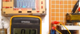
As always, our standard RMAA procedure will act as a ruler. For obvious reasons, the developers did not include tests in the DSD domain - it cannot be “calculated”. But you can “count” the analog output of a source playing DSD. Of course, this must be a high-class DAC with a minimum of intrinsic distortion in order to subtly track all the differences.
This role today is assigned to the brand new TEAC UD-505 with the latest Asahi Kasei AK4497 chips. Among the various upsampling options, the UD-505 offers to transfer any signal into DSD256 or DSD512, even from a Bluetooth receiver. So let’s run a test RMAA track in this mode with a resolution of 24 bits / 44 kHz.
The first column shows the results of the DAC operating in PCM mode with the SD digital filter (i.e. Short Delay) Sharp. Judging only by the numbers, TEAC performed the worst as a stand-alone DSD-PCM converter. Although upsampling was focused on the record frequencies of DSD256 (11.2 MHz) and DSD512 (22.4 MHz); Compared to the original, the noise level has increased by almost 20 dB. The dynamic range of the 24-bit signal has been reduced to 99 dB, which is almost CD resolution. The frequency response has also changed, its decline now more reminiscent of the operation of a DAC in NOS mode.
Now let's compare a couple more DSD playback options. The second will be TEAC again, but now the conversion will be carried out by the audio editor Tascam Hi-Res Editor. The program allows you to obtain DSD files from PCM originals as output. And the third option will be PCM-DSD conversion “on the fly”, performed by the Jriver player software. Looking ahead, I hasten to report that although the signal was taken from the same DAC output, in all cases completely different results were obtained. So much for “delta sigma, which is also delta sigma in Africa.”
It should also be added here that the number of measurements has doubled due to the fact that the UD-505, in turn, has two filters for DSD decoding - wide and narrow. And if in the case of hardware upsampling on the UD-505 their work was not too different from each other, then the playback of “alien” DSD revealed a noticeable difference.
The DSD256 and DSD512 modes were excluded from the experiment, since in comparison with the lower ones they did not show an increase in quality, and upsampling to DSD512 on Jriver also overloaded the computer processor, even causing sound dropouts.
Total: we consider the operation of two modes DSD64 (2.8 MHz), DSD128 (5.6 MHz), passed through the wide and narrow filters of the TEAC UD-505. Here, by the way, are the official parameters of these filters from the DAC manual:
Let's start with basic DSD64 (2.8 MHz). Frequency response curves show that all signals have a certain common point in the region of 4.4 kHz, where they all converge and then diverge in different directions. The original PCM (gray graph) has a slight rise in the HF region due to the Sharp filter - this is a feature of the AK4497 in this mode. The rise is small, less than 0.25 dB; I intentionally increased the scale to make the difference clearer.
The graphs obtained when playing conversion files from Tascam Hi-Res Editor are highlighted in red and black. The most linear result is demonstrated by conversion to DSD on Jriver when selecting the wide filter of the TEAC UD-505 (blue). In the case of narrow (green), on the contrary, the roll-off will be the strongest in the group, but at the same time minimal distortion in the group is demonstrated. On the distortion graph you can see a characteristic rise in the noise floor - this is the noise shaping algorithm at work. In this case, you should not be afraid of it; look at the vertical scale of the graph. Even in the most aggressive version, the overall noise level does not rise above -113 dB.
The differences in the operation of the wide and narrow filters are no longer so obvious at 5.6 MHz, but the differences in the Jriver and Tascam Hi-Res Editor approaches are still clearly visible in the pictures. Jriver has a frequency response closer to the original PCM, while in all variants the noise graphics have merged together. Noise shaping is no longer visible - it is moved beyond the audible range of 20 kHz.
What conclusions can be drawn? As we see, even such a seemingly transformation-resistant format demonstrates completely different behavior at the output. Those. DSD encoders and decoders can operate on multiple protocols. Does it make sense to try DSD as an intermediate container before feeding the PCM original to the DAC? The short answer is yes, it makes sense to try. DSD128 (5.6 MHz) provides basic RMAA measurements that are formally comparable to PCM. The use of higher sampling rates in DSD does not make sense for data storage and does not demonstrate its benefits in terms of audio experience. And here (besides the figures given) you should share your personal impressions as a listener.
It may not be so obvious from the RMAA measurements given, but DSD certainly has its own style and approach to sound. The fact is that the microphone and the human ear “perceive” sound differently. In PCM, Hi-Res soundtrack resolution is growing in a united front. The microphone will equally diligently capture both useful musical texture and harmful artifacts and reflections into the recording. And therefore, even on very detailed acoustic recordings, we are not left with the feeling of being present at some “artificial event.”
The key point of the DSD process is that, on the contrary, it hides the “extra” reverberation, extracting the main solo instrument. It is difficult to comment on this feature within the framework of technical tools. Probably, we are talking about certain temporal characteristics of the signal, which, in combination with noise shaping, gives that specific treatment of musical timbre that is so pleasing to the human ear.
Anyone who has been to a concert hall remembers that there is no “stage” or other characteristics that are usually used in audio journalism. In life, sound, like the holy spirit, lives wherever it wants. You may not be sitting in the best row, but you will be able to focus perfectly on the first quiet sounds of the cello. This moment of “recognition” is very important. But after the microphone of the PCM recorder, this moment will not be described so dramatically: a musical instrument will simply “add” to the rustling of the hall, which will gradually cover them in volume. Do you understand the difference between events? In this sense, the selective tactics of DSD stand somewhat closer to the actual auditory experience than PCM.
And that is why I would recommend DSD only for recordings of natural instruments - symphonic, chamber and other ensembles, where there was no additional processing by studio machinery. No wonder Kevin Gray said that the studio mix in DSD was not like what they heard on the console. Yes it's true. DSD takes the edge off the studio gloss. Multi-channel, equalized, filtered and compressed soundtracks at various levels do not need DSD. Well, or at least needed to disguise too aggressive mastering. So enjoy using DSD, but don't forget to turn it off periodically!
DAC circuits. Brief comparison
Comparison of DAC types (circuits)
The minimalistic R2R DAC circuit (part A of the image above) contains a resistor matrix (ladder). Each of the matrix resistors has a deviation from the required value. This leads to nonlinearity.
The analog filter is designed to remove aliases from digital-to-analog conversion. The analog filter has a smooth change in suppression with increasing frequency. Accordingly, all aliases cannot be deeply suppressed. These aliases can result in audible products generated by ultrasound due to nonlinear distortion (intermodulation distortion).
The analog filter has minimal low-frequency rejection. To suppress aliases in the low-frequency region, an oversampler and a digital filter are used, which has a steeper increase in suppression with frequency than an analog filter (part B of the image above). But a new problem appears: oversampling adds its own aliases that the digital filter struggles with.
Read details here >
The nonlinearity of the resistor array can be solved using a digital sigma-delta modulator (part C of the image above). Because such a modulator is a linear device. But the delta sigma modulator has problems with instability when overloaded.
When the input digital stream is DSD (1-bit sigma delta modulation) instead of PCM, a minimalistic DSD DAC contains a pair of resistors and an analog filter (part D of the image above).
Of course, real DACs are more complex devices than they are shown in the diagrams here. Questions arise about power quality, temperature stability, variation in logical levels, etc. The DAC concepts (parts A, B, C, D in the picture) provide only potential possibilities for developers. And they do not guarantee the best quality for a particular type of DAC.
Read on for details on how these schemes work.
Parameter comparison: resistor R2R, sigma delta PCM, DSD DAC
| Parameter | Resistor (R2R) PCM DAC | Sigma Delta PCM DAC | DSD DAC |
| Method of generating voltage according to code | Resistor matrix | Delta sigma modulator | 1-level chain |
| Analog output filtering | Yes | Yes | Yes |
| Number of voltage references | Number of bits - 1 | 1 or more [if multibit sigma-delta modulator] | 1 |
| Linearity issues in digital-to-analog conversion | Nonlinearity | Linear | Linear |
| Nonlinear distortions of analog circuits | Yes | Yes | Yes |
In analog sigma-delta modulation, level 1 can actually mean 2 (positive and negative).
Read on for details.
What different types of DACs sound like
Quite often the author reads discussions that discuss the preference of one type of DAC over another. The panelists have practical experience of listening to DACs and evaluating their sound quality.
In this article, the author will not consider the quality of recording/mixing/post-production, which is also a matter of assessing the sound quality of a DAC. Because it may be technically impossible to achieve complete identical copies of one record in different formats.
The production of audio tracks has several stages:
- record;
- mixing;
- post-production/mastering;
- conversion to different formats.
How test audio recordings are made
The picture above shows several ways to produce test music recordings.
For some records, some stages may be excluded. Or, a single master recording (the final product of a music production) may be converted into multiple formats.
One acoustic material can be recorded in 2 formats at once. In this case, the difference is in the recording equipment (microphones and their preamplifiers, analog-to-digital converters, etc.) and its settings.
Thus, a comparison of DAC types may involve, at a minimum, a comparison of audio file converters or recording equipment.
The main technical issue that arises when comparing DAC types is the differences in their circuitry.
The picture Comparison of DAC types (circuits) shows the influence of internal modules of digital-to-analog converters on sound quality (distortion level).
There can be many variables to consider when comparing DACs.
For example, in resistor DACs, the resistances can have different variations. This may result in various non-linearities and differences in sound. Even between different instances of the same device model.
Another example: a certain PCM DAC has problems with oversampling aliases, but the DSD DAC being compared has a worse analog filter. Is it possible to guess which one sounds better? Probably not.
Thus, it is impossible to compare the sound of DAC types as abstract devices. But you can compare the sound of specific instances of real digital-to-analog converters, regardless of their internal structure.
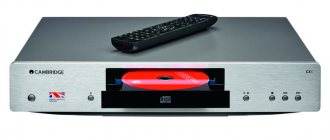
DSD Signalyst DSC1 DAC - DIY
I would like to start a topic about a very interesting DAC based on an open project - Signalyst DSC1 . A special feature of the DAC is that it works only with SDM(DSD) stream, which makes it very simple from a technical point of view.
The author of the idea is Jussi Laako (creator of HQPlayer). The project is dated April 2015. Actively discussed and discussed on computeraudiophile, diyaudio. In RuNet there is a thread on ixbt and Vegalaba.
The idea of a DAC is perfectly simple:
- In an SDM (DSD) stream, the density of logical 1s determines the signal value, so it is enough to calculate the floating average over the stream and thus restore the signal. True, there will be a lot of high-frequency noise in it. The principle of SDM modulation is clearly illustrated on the Analog Devices website.
- At the second stage, we pass the recovered signal through a low-pass filter (not necessarily complex, an analog one is enough) and then on.
The classic implementation is no more complicated (the original Jussi Laako scheme is described):
- For the first stage, 4 shift registers of 8 resistors each are used (see part of the circuit below). Those. we get the sum of 32 SDM flow samples (floating average - values from 0 to 32).
- Next in the original circuit there is an IV converter, a low-pass filter and an output buffer.
A more detailed description of the principle of operation of Signalyst DSC1 from the author of the idea can be found at the link.
By the way, the principle is approximately the same in modern delta sigma chips (only the number of taps in the filter is more than 32) and in DACs based on resistor matrices, if “native DSD support” is declared.
History of development The first implementations of the proposed scheme gave an unpleasant “murmuring” effect. Apparently, it was the products of correlation of the SDM carrier frequency with the signal or noise. Although the reason for the “murmuring” is not fully understood, the most reasonable explanation, from my point of view, was given by Herman (@pm325) in another thread of this forum.
Digital Room Correction - digital correction of room acoustics
Regarding the “murmuring”: the publication Idle tone behavior in Sigma Delta Modulation states that the fundamental frequency of idle tones is proportional to the carrier frequency. There is a suspicion that the dog rummaged somewhere nearby, because the observed noise pattern intensifies in the DSD64-DSD128-DSD256-DSD512 series.
The implications of idle tone aliasing are quite important because it means that an idle tone located
outside the audible range can become audible when having an appropriate amount of DC offset.
Link to an extremely interesting article on this subject provided by Herman (idle tone, limit sycles - specific SDM anomalies).
Already last year, a balanced version of the DAC appeared, in which the “murmur” was completely absent. Versions with transformer output appeared (i.e. the IV converter, LPF filter and output buffer were replaced by a single capacitor and transformer).
Appreciate the beauty of the solution! It’s hard to even call this a DAC!
Assembled boards and balanced kits with different output stages can be easily found and purchased on ebay and taobao. China is omnipresent and the project is open. Cost ~ 200 USD.
Russian version of Sygnalist DSC1 Our compatriot Pavel Pogodin was one of the first (according to my information, I don’t want to offend other participants in the open project) brought DSC1 to a decent level (selected resistors to minimize SNR and transformers, improved mute circuit to eliminate clicks when switching tracks, balanced circuit ).
Andrea Ciuffoli praised his improvements. The article describes in detail the capabilities of playing PCM files via DSC1, and provides photos of two revisions of Pavel's boards.
Because DSC1 only understands the SDM (DSD) stream, then to play PCM content you need to either do a real-time conversion (HQPlayer, for example) or convert the collection to DSD in advance (PCM-DSD Converter, SOX 1.4.2, AuI ConverteR 48×44, Weiss Saracon). From my point of view, this is even good, because... HQPlayer will give odds to almost all DACs in terms of the quality of conversion algorithms (“almost” added for decency).
As far as I know, Jussi Laako, who was initially negative about the idea of a transformer exhaust, changed his mind after testing Pogodin’s boards.
I have version 2.5 of the Pogodin board with transformer exhaust. Additionally, an exhaust according to the Jussi Laako design is being tested.
IMPORTANT: the project is not commercial; Pavel Pogodin is not involved in selling boards. Diagrams, descriptions and possible places of purchase are available at the links above. I am ready to provide my copy for review within MSC/MO.
Plans Early next week I will post my measurements and comparative testing of Signalist DSC1 v2.5 on both exhausts with Auralic Vega.
Description of the measurement technique:
- Test signals are generated in Matlab (24bit 44.1kHz).
- HQPlayer plays the test signal (DSD64/DSD256 upsampling – ADSM7 modulator, poly-sync-shrt-2s filter) via uRendu (NAA) on DSC1.
- DSC analog outputs – to the Focusrite 6i6 analog input in ASIO. Sampling frequency – 192 kHz.
- The signal was received by Matlab (it allows you to control ASIO settings) and further analysis is carried out in it. I can change it if necessary.
I would like to express my gratitude to German (@pm325) and Pavel Pogodin for their help, advice and the opportunity to get acquainted with an interesting design.