This article contains a description of the circuit of the simplest pulse boost converter for car amplifiers (for example, on the TDA7294 or any other microcircuit with bipolar power supply), without unnecessary calculations or theories, only the required minimum. This is really the easiest way today to run a sufficiently high-power amplifier in a car, with an onboard 12 V power supply. The presented inverter can produce a constant power of about 100 W, and with a little modification of the circuit even more.
Diagram and description of the converter
The diagram has been divided into several parts to make it easier to describe and understand the essence of how the parts work.
The green part is an oscillator using the popular TL494 IC. To make the structure as simple as possible, only part of the m/s was used, namely only the generator. The frequency of its operation is determined by elements R4 and C4. For current values (10 kOhm and 1 nF) it is about 30 kHz. By increasing the frequency you can also increase efficiency, but this requires winding the transformer with thinner wires (due to the skin effect).
The yellow part is current amplifiers. They are only used to facilitate reloading of the mosfets' gate power, which relieves the internal output transistors in the TL494. In fact, the circuit in the current configuration will work without them, because the internal transistors of the TL494 can, in principle, drive a single gate without much problem, but in the event of a voltage drop in the power supply, the inverter may become unstable. This is why it is recommended to install them. In this role, almost any transistor can be used to create a complementary pair. The circuit also works well, for example, with a pair of BC547 / BC557, etc.
The orange part is the key output elements. The mosfet turns on when it receives a pulse from the previous stage. The converter turns on the mosfets alternately with the so-called dead time (when both are off). Particular attention should be paid to C8 (10 nF) and R12 (4.7 ohms), because the safety of the transistors depends on them. They are used to suppress overvoltages that occur in inductances during transients. Use a 10 nF capacitor for a minimum voltage of 250 V and a 3.3 ... 4.7 Ohm resistor with a minimum power of 0.5 W.
Different types of mosfets can be selected for the converter; to a large extent, they determine what power and efficiency can be achieved. It is important to choose one with low resistance and high operating current. The IRF3205 was used here, but an IRFZ44n, BUZ11 or IRFP064n for a little more power would work equally well.
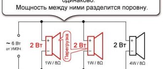
The red part is a transformer with a rectifier. About the transformer and its rewinding will be a little lower. Now let's look at the rectification and filtering circuit. This is a classic symmetrical power supply that uses ultra-fast rectifier diodes or Schottky diodes. In this case, the MBR10100CT diode was used. You also need an output choke and filter capacitors. For a single TDA7294 chip, just use 2200uF + 100nF per leg. Use a normal electrolytic capacitor; there is no need to use capacitors with low ESR.
Standard “music”: what do they offer us?
From the factory, all Rapid 2022 are equipped with a standard Swing head unit (hereinafter referred to as SHU) with a 6.5” touch screen. In the two lower trim levels, the buyer will receive 4 speakers. This means two main 16 cm radiators with paper diffusers in the front doors and 2 separate tweeters. They are located next to the door release handles in cars with mechanical mirrors, or in the mirror caps in cars with electric mirrors. In the Ambition and Style trim levels, 6 speakers are installed from the factory: in addition to the existing 4 radiators in the front, 16 cm wideband speakers appear in the rear doors. This is what both look like.
For an additional fee, you can order a Bolero SHGU with an 8” screen from Skoda. Externally, it is more modern and will offer a little more functional “goodies”, but in terms of amplifier power, sound quality and available sound settings it is no different from Swing. Both devices have bass, mid and treble controls, as well as audio focus (front-rear-left-right). Unfortunately, there is no full-fledged multi-band equalizer.
The Volkswagen Polo 2022 for all trim levels, except the older one, has a SHGU with a 6.5” screen in the base (they are not given their own name within the Volkswagen catalog, but they are exactly the same Skoda Swing) in conjunction with 4 speakers in the front doors (2 LF + 2 HF). And in the older Exclusive configuration there is the Skoda ShGU Bolero with an 8” screen, and there are already 6 speakers. The speakers themselves and their location are exactly like in the Rapid.
Why so much attention to the standard audio system? Yes, because few people would dare to take out the entire “sound” in order to put on something completely different. At a minimum, almost all owners keep SHGU. Although it may not shine with sound quality, it is not just a multimedia entertainment device and a rear view camera display (who has one), but also a remote control for controlling the settings of the car itself. It would be a shame to lose these settings.
Fortunately, even on the basis of standard multimedia, you can implement several levels of upgrade of the sound system. We advise you to proceed step by step, as the standard “music” of the new Rapid/Polo sounds really good.
Especially compared to Korean and French models, as well as in comparison with Lada Vesta. And especially if we are talking about the factory Rapid/Polo audio system with 6 speakers. She has very good sound potential! Which, admittedly, is surprising for a car of this class.
To raise the sound quality and volume to a truly new level, you will have to spend at least 30-40 thousand. If you are not ready for this in the format of a one-time expenditure, then start a step-by-step improvement in the sequence indicated below. It is possible that at some point you will consider the improvements sufficient and decide to stop there.
Inverter fuses
It would be better to replace the output current control circuit with a so-called electronic fuse, which in the event of a short circuit will turn off the converters (restarting will be required). The current control circuitry in an inverter with a power made for a specific system (in this case a TDA7294 stereo for an 8 ohm speaker) can only turn off the inverter during bass periods when the amplifier is drawing more power.
The control module has a fuse in the form of resistor R11. We use a standard 4.7R 0.25W resistor - in the event of a short circuit in the TL494 or current amplifiers, the resistor immediately burns out. The power section is protected by a 10 A fuse. In the above circuit, a short circuit at the output causes its immediate combustion.
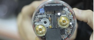
Subwoofer amplifier for car
A high-quality 100-watt amplifier for a car subwoofer, assembled on the TDA7294 chip, has a power higher than that on the TDA1562 chip (50 W). The amplifier uses a 12-volt converter for two 40-watt speakers. It contains a low-pass filter, placed on one side of the board, and there are three blocks in the circuit.
Power Converter Assembly
You can etch a full-fledged printed circuit board, or you can use a universal breadboard. It is important that the current paths are as short and thick as possible.
Useful: 1000 watt audio power amplifier
First we collect the green, yellow and orange parts. In this case, the circuit is powered through a small light bulb (for example, 10 W) or set the current limit to 200 mA on the power supply. Connect one oscilloscope probe to the power supply plus, and the other to the UT amplifiers. You should see a rectangular waveform with an amplitude around the supply voltage. The waveform should be very similar to the photo.
If the signal is not displayed, check the correct assembly and functionality of the green and yellow sections of the UPS.
Then we connect an oscilloscope in parallel with the mosfets and observe the signal shape there. It should be a rectangle with an amplitude similar to the supply voltage. If it is not visible, this means that a damaged mosfet was installed (or it was soldered incorrectly).
If everything is in order, we can start winding the transformer.
Level one – Shvi doors
To improve the sound of a standard audio system without changing anything from the equipment, it is necessary to make noise and vibration insulation of at least the doors. That is, glue them from the inside with special vibration- and noise-absorbing materials in several layers. You can do this yourself, but it’s better to go to any decent workshop where they do car repairs. The sound will be more pleasant overall, cleaner in the bass area. Pasting the entire body with special materials from the inside will reduce the overall noise while driving, but will no longer affect the sound quality of the music. On the other hand, reducing background noise will make listening more comfortable, which can also be called an improvement. But complete sound insulation costs at least 25,000 rubles, while for 4 doors in a workshop they will charge about 7,000, including materials.
Winding the transformer
The transformer is the most important element and the most complex. First, you need to get the ferrite core. You can get it from an ATX power supply or other switching converter. It is extremely important that this is a core without a gap, otherwise the inertial current of the converter will be higher and the efficiency will be significantly lower. In the worst case, it may not work at all. To disassemble such a transformer, heat it in boiling water, because then the resin will soften. Then, using a rag, break apart the hot transformer. It is important not to damage the core. Then we remove the factory windings and wind new ones in accordance with the instructions below.
Let's start with the primary winding. In it, two windings must be wound 3 turns at a time, where the beginning of the second is the end of the first. Both windings are wound in the same direction. Due to the fact that the inverter operates at a high frequency, a skin effect occurs. Therefore, you should not wind the transformer with one thick wire, as is the case with classic transformers. For this inverter we will wind 4 wires of 0.3 mm each. The winding should look something like this:
Now isolate the primary from the secondary. For example, layers of tape. It's time to wind the secondary winding. Wind two windings of 7 turns each. The transformer is ready.
Instead of the main fuse, we insert a lamp of significant power (preferably 50 W, so that at low current it does not cause a significant voltage drop). We measure the current consumed by the converter, it should be 100-250 mA. The waveform on the oscilloscope should be rectangular with the required amplitude.
The inverter is almost finished. All that remains is to mount a rectifier circuit with ultra-fast diodes or Schottky diodes. Next, install the choke and filter capacitors.
An output choke will be required in this inverter. With a stretch, it can work without it, but its efficiency will become less and a squeaking noise may be heard under load. The choke is wound onto the powder ring. You can also desolder it from an ATX power supply. The winding is double, 17 turns each (the value was chosen by trial and error).
The inverter output voltage should be approximately +/- 36 V. This is the optimal value for TDA7294 chips.
The inverter must be loaded for testing with an electronic load or a high-power 50 ohm resistor. The resistor will output about 100 watts of power as heat. The output voltage of the converter under this load should not fall below 32 V. The warmest element should be the rectifier diodes. The transformer should get slightly warm, just like the mosfets. The 100W test should take 10 minutes.
What sound quality will there be with this connection?
It should be said right away that all the manipulations described in this article are justified if you want to improve the sound quality of your standard speaker system with little effort. Adding a subwoofer will greatly expand the dynamic range of the music tracks you can listen to. The sound will become deeper and more voluminous.
But you still shouldn’t expect a significant increase in quality, since most standard radios, in principle, cannot produce high-quality sound. If you chose the first option, how to connect a subwoofer to a standard radio, with unsoldering the line outputs, the sound quality will be higher than other options. If you used an external high-level converter or high-level inputs in the amplifier, the quality will be slightly worse.
This will probably be enough for most people. If not, there is only one way out - change the head unit or install a separate radio with the functionality you need and a sufficient number of linear outputs.
Hello everyone, friends! In one of my previous entries I wrote that I bought an Alpine-1243BR sub. Of course, it was not bought just for the sake of a trinket in the trunk, but was waiting for the moment when I installed it. And so, last Monday, having finally returned from vacation and got to the car, I started connecting. First of all, go to the store for a set of wires, an amplifier and a signal converter. I bought everything at the Autocasta store. Since the sub has a rated power of 250W and a maximum power of 800 and an impedance of 4 Ohms, I selected an amplifier with a rating of > 250W at the specified resistance. As a result, the choice fell on MOMO D-800. Its rating with a resistance of 4 Ohms is 340 W, which is slightly higher than what the sub requires, but a small power reserve has never harmed anyone
One of the nice advantages of this amp is the ability to connect rem (more on that later) and an external bass regulator.
I also bought the cables as a set. Aria AAK 2.04 - one of its worst drawbacks is that there was not enough five-meter power cable for a comfortable power connection. I had to buy another meter and connect it later. This, of course, can be avoided by running the cable on the left side of the car, and not on the right, as I did. Or be content with a short section that remains in the trunk and connect the amplifier only to it. In fact, this may well be enough, but limiting yourself is somehow not comme il faut.
And the list of purchases needed to connect a subwoofer was completed by the Audio Nova LOC.1 converter. In my opinion, it’s just cheap and cheerful
So, about the connection: some points will be described in detail, and some will have to be talked about only nominally, because I connected it together with a friend, and while I was doing my task, he managed to do something else and close it, without giving me the opportunity to take a photo. First of all, we started connecting the power cable to the plus. It is taken from the battery and stretches under the hood to the right side of the car, simultaneously clinging to it with clamps.
After the cable was brought into the cabin, it was lowered along the fender to the threshold and then thrown through the right threshold to the trunk. In fact, separate posts are written about how to remove thresholds, but you and I, I hope, will do without it, we will assume that we already know how to do it. Fortunately, there’s really nothing complicated there (or it just seems so to me, because over the last month I’ve already removed and assembled these rapids on the Polo a bunch of times).
The minus is taken from the car body. There are protruding bolts in the trunk; we put a pre-prepared power cable with a terminal over them and clamp it with the bolt. There is a photo of this bolt below, read and see, but for now just a photo of the terminal.
After laying the power cables, we moved on to connecting the audio cables. It was necessary to remove the radio and, first of all, make the discovery for myself that the stock, it turns out, is single-din)) and under it there is emptiness. This emptiness, by the way, played into its hands, because... The signal converter was pushed into this opening, where it was successfully secured. Acoustic + and - were taken from the rear speakers. They did not pin out the connectors in the radio, they crashed into the cables themselves.
By the way, I finally found out what kind of radio I have installed)) VW R340G Visteon made in India (6RF 035 187 E) - this is the part number stamped on the back cover.
The signal cable was laid along the starboard side, but along the ceiling, in order to avoid interference from the power cables. For trial testing, rem was short-circuited to the “+” of the amplifier and started. Started playing. This was the end of the first day of installation. With the rem and plus closed, the amplifier did not turn off in principle, which is why it was necessary to climb into it through the interior, recline the seats and disconnect it with a screwdriver. Inconvenient, don't you agree? Therefore, the question arose before me, how to make the amplifier turn on itself when I start the car and turn off when I get out of it. Fortunately, this is exactly what rem exists for. It would seem like a fairly trivial task - take the turn-on signal from the radio, connect it to the rem amplifier and know only joy. But no, everything turned out to be somewhat more complicated and required time for reflection and even a post in the local Chelyabinsk group drive2, where I asked for ideas on how to connect rem. The reason for my stupor is simple - the radio has a constant plus and is controlled via a can-bus, you can remove the signal from it to turn on the amplifier only by disassembling it, unsoldering it and hooking it up using a microcontroller, soldering iron and damn it. This, of course, is an option, but I didn’t want to disassemble the radio “at all.” I started looking for other options. For our technical specifications - turning on the amplifier simultaneously with the ignition and turning it off when you leave the car, in principle, any plus that appears simultaneously with the ignition is suitable. The options are as follows: throw the hell out of this head and buy one on Android, remove the plus from the ACC of the ignition switch, from the fuses or... from the light switching unit. We settled on the last option when the previous three disappeared. It was simply too lazy to get to the ignition switch and deal with it, and I couldn’t remove the fuses - the required pin (49, if I remember correctly), the signaling was already powered and they didn’t bother getting into the wiring of the pins again.
So, on the second day of the sound installation (or rather, even on the 3rd, since the 2nd was entirely spent on finding a suitable solution), we came to the conclusion that rem would be taken from the light switching unit in such an original way.
Unfortunately, it was not possible to pin out the connector - apparently, my hands were not sharpened for that and I had to cut into the wire. Using a scientific method, they determined where the plus comes when the ignition is turned on and crashed into it. We tested it, everything turned out to be successful.
Thus, we got a ready-made rem and threw it along the left side of the car, under the same long-suffering thresholds (did I already say that almost all day long I do nothing but remove and install the thresholds?) We spent more time under the same left threshold and a bass level controller from the amplifier, secured it with double-sided tape near the driver’s left leg. It doesn’t interfere there at all, and, in principle, is accessible enough for quick adjustments, and does not blind you with a light bulb in your face, but softly and naturally shines into your left toe.
At this point, the installation itself could be considered complete if it weren’t for the task of carefully placing the subwoofer and amplifier in the trunk itself. Firstly, in addition to the main cooling radiators, the amplifier also has ventilation holes at the bottom; obviously, they cannot be covered. Accordingly, we come to the second thing - it should not stand on the trunk carpet and! If you attach it somewhere, then there will be no extra holes in the car. And then I looked at the guys who were drilling the back shelf or cover - no thanks. And finally, thirdly, I had to try to do it cheaply, concisely and simply.
Of course, I won’t list all the options for how I wanted to do it. I’ll just say that I bought a dozen insulation fasteners and tried to play with them, but it didn’t burn out. Although, in principle, if you get confused and calculate everything correctly, you can place the amplifier under the trunk roof without making extra holes in the car body.
And after some ordeal and research, I came to a simple, cheap, spectacular and effective solution. (As I like to say, the production is also a bummer, although the original sounds a little different and a little rougher)
I bought a couple of wooden slats and sawed them, making several “rails”, in the end only two of which were useful to me. I sawed in large quantities, because... there was an idea to make a small box for the amplifier and put it in there, but, again, “what for is it necessary” - let’s say together
For overall beauty and unity with the subwoofer, I covered the prepared rails with velor and screwed them to the subwoofer box, and placed the amplifier on them. It turned out inexpensive, simple, relatively nice and even laconic (unlike this post).
This allowed the wires to be neatly hidden and gave an overall seamless, finished look to the trunk.
Regarding the sub, I can say the following: it has not been tuned yet, there are five or more knobs on the amplifier, and in the coming days I will be running from the amp to the driver’s seat and back, I will be turning the settings back and forth. But in general, the banging is banging, the head hurts, on the street banging with the windows closed, no rattling, farting or other musical stream can be heard (thanks to sound insulation, which will be discussed in the next post) Costs for the final items directly related to car audio: used subwoofer — 2000 rub. Amplifier Momo D-800 - 5000 rub. Set of wires - 2000 rub. Meter of power cable and connector - 550 rub. (sort of)
Signal converter - 650 rub.
Phew, I finally finished writing, and you, dear friend, finished reading. As always, I say goodbye to everyone warmly and look forward to your hearts and comments below. All the best, see you again!
The last artifact for this post is my dealer's ad for some crazy soundproofing for a license plate. Vibra 3 mm + STP BiPlast Premium 15A. Yes, the sign mount was rattling. Yes, the trunk and trunk lid are taped with Shumka. Yes, in several layers. And yes, it's enough))
Some friends gave me a subwoofer for my birthday. A good one with a body, Alpine S-Type, 12 inches. He played in both Oda and Kalina. It's time to install it in Polo. But there is one problem. The standard radio does not have linear outputs to the amplifier. The Germans did not foresee this during development. Naturally, there is always a choice of actions. The first thing is to change the head unit. The second is to “unsolder” the linear outputs from the radio. And the easiest way is to connect via a Level Converter.
Naturally, we took the simple and safe route.
A Mystery MAD-HL Level Converter
was purchased at a nearby store . There was no alternative in this store, and I wasn’t going to go all over the city looking for a device that I didn’t know how it would work. And then there’s the price tag: a penny, 190.00 rubles. Good for testing!
Having collected everything in a heap, and this is the VELAS VC 4606 amplifier, Alpine S-type 12″ cabinet subwoofer, wires for connection, I dragged everything into the car and began laying out the wiring.
I found the hole for the positive wire on the right side of the engine shield (behind the glove compartment). As specifically provided for. Afterwards, the removal of the threshold trim began. But this required removing the upper and middle trim of the right pillar.
I was surprised that everything had to be dismantled without a screwdriver or other tools. I removed all the parts using my hands only. Nothing broke or cracked, all the latches remained in place.
After laying the wires, the removal of the radio began.
Taking it off turned out to be a piece of cake. We pry up the decorative panel, unscrew the 4 screws and remove the GU.
It turns out to be Chinese...
We connect the level converter to the wires of the rear speakers, observing the polarity, install the bulb under the hood, connect the sub and amplifier...
Everything works great, but requires some configuration. The sub is pounding like crazy. I had to turn down the low frequencies on the radio by -7. There is not enough time to set everything up. I will mount the amplifier on the rear shelf in the trunk as soon as the Shumka appears so that I don’t have to redo everything five times. There was no need to cut any wires. There are ISO connectors on the radio, I just plugged the wires into the chip.
Radio tape recorders
Good and loud music in the car - this is what many car enthusiasts want, especially young people. But there is a problem: not every car is already equipped with a high-quality audio system. Therefore, in this article we will try to fully and clearly explain how you can independently connect a subwoofer to a standard radio, to the one you already have, installed by the manufacturer.
I really want to make a reservation right away. What if you decide to do all the work yourself and connect an active subwoofer, then the responsibility will be yours personally. But there is no need to experience unnecessary fears, if your hands can hold a screwdriver and pliers, then connecting the amplifier to the standard radio will be within your power.
Do I need a voltage stabilizer?
Stabilizing the output voltage on the power supply of an audio amplifier is a bad idea. The amplifier has a very non-linear power consumption, in addition, when the bass passes, it can consume a lot of energy (per pulse). Feedback to control the output voltage may interfere with the response to increased power consumption.
For testing, the unit was powered by a 12 V 60 A adapter. In addition, it is advisable to install fuses on the +36 V and -36 V lines. The board is sized to fit into car radio housings, and all elements can be easily cooled with one fan if necessary.