The topic of speaker placement in a listening room has been the subject of much discussion and controversy. Particularly enthusiastic people wrote reports and books on this topic, trying to give the reader some kind of universal truth in a variety of terms, formulas, drawings and graphs.
One of these enthusiasts is the founder of Cardas Audio, George Cardas. Based on his experience, he was one of the first to introduce the concept of the “golden ratio” - or Fibonacci ratio - into the audio/video industry.
By applying this constant to his products, George claims that using the Golden Ratio when placing speakers in listening rooms produces the best results possible for that room. Thanks to this positioning, room resonances minimally disturb the listener, as a result of which the sound of the systems reaches a new level. Is his statement true? Let's check!
What should the bass reflex resonance frequency be?
The resonance frequency of the bass reflex (in general) should be 1/3 (33%) lower than the resonance frequency of the same speaker in the same box with the bass reflex hole closed.
Example : Fres. dynamics in GZ = 60 Hz. 60 x 0.33 = 20Hz. 60-20 = 40 Hz.
The calculated resonant frequency of the FI in this example should be 40 Hz.
For this frequency, I then consider the diameter and length of the bass reflex to match the volume of the given box. Now let’s look at more scientific options for calculating the bass reflex.
Hey, on the ferry!
The horn is the oldest and, perhaps, the most provocative type of acoustic design. It looks cool, if not shocking, it sounds bright, and at times... In old films, characters sometimes shout something into each other's mouthpieces, and the characteristic coloring of such a sound has long become a meme in both the music and film worlds.
Avantgarde Acoustics Trio with 2.25m Basshorn XD horn array
Of course, today's acoustics have moved very far from the tin funnel with a handle, but the principle of operation is still the same - the horn increases the air resistance for better coordination with the relatively high mechanical resistance of the moving speaker system. Thus, its efficiency increases, and at the same time a clear directionality of radiation is formed. Unlike all previously described designs, the horn is most often used in high-frequency speaker sections. The reason is simple - its cross-section increases exponentially, and the lower the reproduced frequency, the larger the size of the output hole should be - already at 60 Hz a bell with a diameter of 1.8 m is required. It is clear that such monstrous designs are more suitable for stadium concerts, where they really can be found periodically.
The main trump card of adherents of horn playback is that acoustic amplification allows, for a given sound output, to reduce the membrane stroke, and therefore increase sensitivity and improve musical resolution. Yes, yes, again a nod to the owners of single-ended tube circuits. In addition, with proper calculation, bells can play the role of acoustic filters, sharply cutting off sound outside their band and allowing you to limit yourself to the simplest, and therefore introduce minimal distortion, electric crossovers, and sometimes even do without them.
Realhorns systems - special acoustics for special occasions
Skeptics never tire of reminding us of the characteristic horn coloring, which is especially noticeable on vocals and gives it a characteristic nasal quality. It’s really not easy to overcome this problem, although judging by the way the best examples of High-End horns play, it’s quite possible.
Horn
Pros: High acoustic efficiency, which means excellent sensitivity and good musical resolution of the system.
Disadvantages: Characteristic, difficult-to-eliminate sound coloration, non-childish sizes of mid- and especially low-frequency structures.
Option #1. A simple option for calculating the size of a bass reflex
This option is suitable for the lazy. We need to know the bass reflex tuning frequency for a given speaker. It is often indicated by speaker manufacturers in technical specifications, for example on packaging.
Where:
- F—FI tuning frequency;
- C is the speed of sound;
- n - number = 3.14...;
- S—hole area;
- L - effective pipe length (pipe length plus 5 percent);
- V is the volume of the body.
There are meters and hertz everywhere.
Accordingly, the ratio of the hole area to the length of the bass reflex:
Rice. 1. Formula for the ratio of the hole area to the length of the bass reflex
that is, when the hole area is doubled (two ports), the length of each bass reflex doubles. Making a narrow bass reflex to reduce the length of the pipe is impractical - the flow speed in it increases (there should be no more than 5% of the speed of sound! I made a mistake from memory)
It also doesn’t make sense to make a very wide and long bass reflex at the same time - its length should not be greater than the wavelength at the resonance frequency, so that there are no standing waves, but in general it turns out to be several meters, so it’s difficult to make a mistake here.
Making your own port
The bass reflex, just like the speaker, is involved in sound reproduction. To avoid the interference effect, the channel is placed closer to the low-frequency emitter at a distance not exceeding its wavelength. Rigid structures are used as FI, for example, plastic sewer pipes are used in homemade products.
But when trying to calculate a bass reflex for a subwoofer, consumers are faced with the fact that the diameter of such pipes does not coincide with the calculated values, so the pipe is made from a dense material at hand - whatman paper. In order to make a channel yourself, you will need:
According to the calculations performed, a base with a diameter slightly smaller than the calculated one is selected. Then, using a mandrel, several layers of newsprint treated with glue are wound onto it. Winding is carried out tightly, avoiding air getting between the layers.
A strip cut from whatman paper, the width of which coincides with the length of the tube, is wound in several turns on the surface of newsprint. In this case, epoxy glue is applied before each turn. It is obtained by mixing resin and hardener according to the instructions. After all the turns have been completed, the product is wrapped in a circle with thread to impart rigidity and placed to dry.
After a day, the base is removed. If difficulties arise, it can be broken from the inside and taken out in parts. A manufactured channel of this type has good strength and is easily subject to additional processing. Next, the resulting tube is installed in the hole of the speaker, but not all the way, and listening to the sound begins. In the factory, a special device is used. Such a device operates on the basis of a multivibrator, which is tuned to the resonant frequency of the dynamic head. After connecting the speaker, the generator starts and the length of the pipe is adjusted to the maximum fluctuation of air in it.
You can do the same setup yourself. To do this, a low frequency signal is supplied to the input. The tube is moved forward or immersed inside the box, and then the volume of escaping air is assessed. Having established the position of its maximum outlet, the excess pipe is removed from the outside, and the port itself is sealed. If desired, to give the structure a finished look, open the pipes, but you can do without it.
Option No. 2
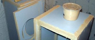
First of all, guided by Fig. 2 and the table, it is necessary to make a “standard volume” - a sealed plywood box, all joints of which are carefully adjusted, glued and coated with plasticine to avoid air leaks.
Rice. 2. Drawing of a plywood box
| Speaker diffuser diameter, mm | Dimensions, mm | ||
| A | IN | WITH | |
| 200 | 255 | 220 | 170 |
| 250 | 360 | 220 | 220 |
| 300 | 360 | 220 | 270 |
| 375 | 510 | 220 | 335 |
Next, the natural resonance frequency of the loudspeaker located in free space is measured. To do this, it is suspended in the air away from large objects (furniture, walls, ceiling). The measurement diagram is shown in Fig. 3.
Rice. 3. Scheme for measuring Till-Small parameters
Here ZG is a calibrated sound generator, V is an alternating current tube voltmeter and R is a resistor with a resistance of 100–1000 ohms (at higher resistance values the measurement is more accurate).
By rotating the frequency adjustment knob of the sound generator in the range from 15-20 to 200-250 Hz, achieve the maximum deflection of the voltmeter needle. The frequency at which the deviation is maximum is the resonant frequency of the loudspeaker in free space Fв.
The next stage is to determine the resonant frequency of the loudspeaker Fв when it is operating at a “standard volume”. To do this, the loudspeaker is placed with a diffuser on the hole of a “standard volume” and pressed lightly to avoid air leaks at the junction of the surfaces. The method for determining the resonance frequency is the same, but in this case it will be 2–4 times higher.
Rice. 4. Nomogram for determining the resonant frequency of a loudspeaker Fв Fig. 5. An example of determining the resonant frequency of a loudspeaker on a nomogram
Knowing these two frequencies, the dimensions of the bass reflex are found using nomograms. Depending on the diameter of the loudspeaker diffuser, select the nomogram shown in Fig. 5 (for diameter 200 mm). Using the selected nomogram, the volume of the bass reflex is determined by connecting the points corresponding to the found frequencies on the “Resonant frequency” axes with a straight line.
Rice. 6. Nomogram for determining the optimal volume of the box
Fв (see Fig. 5 point A) and “Resonant frequency” Fя (point B). Mark the point of intersection with the auxiliary axis and from here draw a second straight line through point D to the “optimal volume” axis. The value corresponding to the new intersection point E is the required volume.
If there are no special considerations for designing a box of a special configuration, then the calculation of its internal dimensions for a given volume can be made using the nomogram shown in Fig. 6. The width of the bass reflex will be equal to 1.4 times the height, and the height will be equal to 1.4 times the depth. Using the nomogram is not difficult: draw a straight line between the extreme axes on which the volume values are plotted. The intersection points of the straight line with the A, B, C axes will determine the width, height and depth of the box. The diameter of the cutout for the loudspeaker is taken equal to size C indicated in the table.
Rice. 7. Nomogram for determining the size of the box and the diameter of the cutout for the bass reflex
Next, having specified the diameter of the tunnel, you need to determine its length and check whether it fits into the bass reflex box. The length of the tunnel is found from the graphs shown in Fig. 8, for three internal diameters: graphs A - for a diameter of 50 mm, B - for a diameter of 75 mm and B - for a diameter of 120 mm. Having selected the appropriate graphs, the length of the tunnel is found from the frequency Fb and the volume of the bass reflex, determined earlier (example in Fig. 7, B). It should be 35–40 mm less than the internal depth of the box. If this does not work, you can slightly change the configuration of the box, maintaining its volume, or take a different tunnel diameter.
Rice. 8. Graphs for determining the length of the bass reflex tunnel
The bass reflex is made of plywood about 30 mm thick. If you don’t have such thick plywood, then to increase rigidity you need to glue 25x75 mm bars diagonally or crosswise inside the box. The box is assembled with screws and glue and all seams are sealed. It is recommended to fasten the back wall with screws (five pieces on one side) with a felt pad. The tunnel is made from a thick-walled cardboard tube.
Having made a bass reflex and installed a loudspeaker in it, we begin to dampen it. To do this, it is recommended to completely cover the loudspeaker from the back with a layer of glass wool 25–50 mm thick, attaching it to the board around the diffuser holder using a ring screwed with screws or screws.
Rice. 9. Scheme for checking the adequacy of damping
The sufficiency of damping is checked using the diagram shown in Fig. 9. The resistance of resistor R is taken to be about 0.5 ohms. If the damping coefficient K of the amplifier with which the unit will work is known, and the resistance of the loudspeaker voice coil to alternating current r is known, then it can be determined from the formula R = r/K ohm.
Move the switch from one position to another, listen to the click in the loudspeaker. If it is quite distinct and there is no “rumbling” or “ringing”, then the damping is sufficient. The final decision is made after listening to orchestral music with well-defined bass and high notes.
Types of speaker systems
Sound is a vibration that has a mechanical origin, propagating under pressure caused by a radiation source. An acoustic system, which is a sound column, converts electrical signals into mechanical signals perceived by the human ear. The frequency of these oscillations ranges from 20 Hz to 20 kHz. There are different types of speaker systems:
- Acoustic labyrinth . It looks like a labyrinth, made in the form of a tunnel located in the middle of the column. Its purpose is to enhance low frequencies due to many bends. The internal walls of the labyrinth are covered with a damping coating, due to which the labyrinth does not introduce parasitic overtones into the sound.
- The volume of air and the resonance frequency to which the channel is tuned depend on the size and type of the bass reflex port. The volume of air in the channel begins to resonate and enhance frequency reproduction when the moment comes when the diffuser emits the frequency for which the bass reflex is designed.
The classic tunnel is circular in shape. But to increase the useful internal area, it is often given a slotted appearance. Refusal of the cylindrical shape of the tunnel makes it possible to reduce its length and reduce the noise that occurs when air is released.
If there are errors in the calculation of a slotted bass reflex, it is much more difficult to configure it than the classic type, since it is manufactured together with the speaker. The calculation itself is more complicated than for closed-type systems: in addition to the volume of the box, the adjustable resonance frequency is taken into account. The optimal dimensions are selected taking into account the amplitude-frequency characteristics of the speaker, namely its uniformity.
Option #3. Calculation of the bass reflex size according to the nomogram
rice.
10. Nomogram for calculating the size of the bass reflex In the low frequency range, the operation of the loudspeaker does not depend on the shape of the box or the type of bass reflex, but is determined only by two acoustic design parameters - the volume of the bass reflex box V and its tuning frequency Fb. The calculation of acoustic design basically comes down to finding these quantities.
In order to understand the methodology for calculating loudspeakers using a nomogram, let's consider several examples.
Example 1. Calculate the optimal acoustic design for a known low-frequency driver. Let's assume that using measurements the head parameters are determined: Qa=3.2, Qe=0.33, Vas=0.120m3, fs=40 Hz. When operating from an amplifier with zero output resistance (Rg=0), the Qt of the head will be 0.3. Let's mark the point Qt=0.3 on the abscissa axis, draw a straight line perpendicular to the axis through it and find the ordinates of the points of intersection of the straight line with the curves in the upper and lower parts of the nomogram: Vas/V=3, fb/fs=1.25, f3/fs= 1.47. Substituting the measured values of the head parameters Vas=0.120m3, fs=40 Hz into the resulting ratios, we find: V=0.04 m3, fb=50 Hz, f3=59 Hz. Thus, if you do not take measures to additionally regulate Qt, to obtain a smooth frequency response of the loudspeaker, it is enough to place a given head in a bass reflex box with a volume of 0.04 m3 and tune it to a frequency of 50 Hz. The cutoff frequency of the loudspeaker will be equal to 59 Hz.
Example 2. For the same original head with Qa = 3.2, Qe = 0.33, Vas = 0.120 m3, fs = 40 Hz, it is necessary to calculate the parameters of the bass reflex box so that the cutoff frequency of the loudspeaker is equal to 35 Hz. At a specified cutoff frequency, the calculation begins by determining f3/fs. In the case under consideration, f3/fs=0.875. Next, a straight line is drawn through the point with ordinate 0.875 on the f3/fs curve, perpendicular to the abscissa axis, and the coordinates of its intersection points with the Vas/V and fb/fs curves are determined, i.e. Qt=0.415, Vas/V=1.05, fb/ fs =0.93. Substituting the head parameter values Vas=0.12m3, fs=40 Hz into the resulting ratios, we find V=0.114 m3, fb=37 Hz. Therefore, in order to obtain a smooth frequency response of a loudspeaker with a cutoff frequency of f3 = 35 Hz, the volume of the bass reflex box should be 0.114 m3, and the tuning frequency should be 37 Hz. In addition, since the required value of the total Q of the head differs from the measured one (when operating from an amplifier with zero output impedance Qt = 0.3), additional adjustment of this parameter will be required to achieve the desired shape of the frequency response.
Example 3 . A low-frequency head is given (Qa=3.2, Qe=0.33, Vas=0.12m3, fs=40 Hz) and the volume of acoustic design is set to 19 V=0.06 m3. It is required to design a loudspeaker with a smooth frequency response. Let's define the ratio Vas/V =2. Through the point with ordinate 2 on the Vas/V curve we draw a straight line perpendicular to the abscissa axis and find the coordinates of its intersection points with the fb/fs and f3/fs curves: Qt=0.345; fb/fs=1,1; f3/fs=1,2. Substituting the values of the head parameters into the last ratios, we find fb=44 Hz, f3=48 Hz. Thus, in order to obtain a smooth frequency response of the loudspeaker with a given head and in a box of the specified dimensions, you will need to adjust the bass reflex box to a frequency of fb = 44 Hz and, using control means, bring the total Q of the head to a value of 0.345.
Direct algorithm for creating the housing itself for a car subwoofer
Here's what you need to know:
- The most optimal shape would be a truncated pyramid, since it is the most universal;
- The slope of the rear wall should be approximately 23 degrees, since the vast majority of modern passenger cars have an interior with the rear seat backs tilted at exactly this angle;
- It is imperative to calculate the volume of the body in accordance with the dimensions of the free space of the trunk (see Soundproofing the trunk in a set of measures to reduce noise in the cabin).
Recommendations for calculating enclosures and subwoofer pipes
Calculation of the FI box using JBL SpeakerShop and BassPort programs. — DRIVE2
Before you begin calculating the bass reflex enclosure for a specific subwoofer speaker, you need to find out what Thiel-Small parameters the speaker has and understand what they are: For an adequate calculation, three parameters are enough. Fs is the resonant frequency of the speaker, indicated in Hz (hertz). Vas is the equivalent volume indicated in liters.
Qts – total quality factor of the speaker.
1. Calculation of the net volume and tuning frequency of the bass reflex. To do this, you need a program for calculating subwoofer enclosures, there are quite a lot of them, both paid and free, the most popular and easy to use is the JBL SpeakerShop program. In the program, you need to specify the Thiel-Small parameters, selecting the volume of the box and setting the bass reflex port, to obtain the required frequency response graph.
2. Calculation of the bass reflex port. Very quickly and conveniently, and most importantly with great accuracy, you can calculate the port at the desired frequency in the BassPort program.
We enter in the program: The required frequency of tuning the FI port The previously obtained net volume of the box The effective area of the speaker diffuser (measured, the length along the center of the speaker from one middle of the suspension to the opposite middle of the suspension) The maximum stroke of the diffuser in one direction (indicated in the instructions or on the manufacturer’s website as Xmax , can be indicated either in one direction or in both directions at once) Select the port cross-section Enter the dimensions of the port Press the calculate button and get the required port length “L”, as well as other equally important data, in particular - the displacement of the port, which will be added to the volume of the subwoofer enclosure.
3. We calculate the total volume of the FI case. In the JBL SpeakerShop program, we learned what pure volume is needed for a particular subwoofer, as well as what frequency is best to set the FI port. At Bassport, we calculated how long the FI port should be based on its area, and found out how much volume the port would occupy.
Now we add up: net volume + port volume + 3 – 4 liters (volume displaced by the speaker) and we get the total internal volume of the future FI case. If roundings, stiffening ribs are used in the housing, if the housing is slotted, etc., this must also be taken into account in the total volume. Example: *Net volume - 45 liters.
*Slotted port, area 140 cubic cm. at 36 Hz - 8.5 l., plus 3.8 l. on the port wall of 18 mm. plywood. *Displacement by speaker - 3 liters. *Total - 60.3 liters. the total volume of the hull FI. Now, it would seem the most incomprehensible thing is how to obtain the dimensions of the hull based on the known displacement? We have a volume of 60.3 liters.
Advice
We measure the trunk, see what dimensions suit us, for example: height - 40 cm, length - 60 cm, we just need to find out the width. We subtract the thickness of the walls from the height and length (let it be 18 mm plywood) and we get: height - 36.4 cm, length 56.4 cm.
Now we calculate: 60.3 * 1000 / 36.4 / 56.4 = 29.4 - the width of the body, without walls, with walls 33 cm.
This is what the calculation of a bass reflex enclosure for a specific subwoofer speaker looks like. I ask you not to take this article as a clear guide to making a FI subwoofer, there are a lot of points and subtleties that are not taken into account.
Who is interested in car audio, join vk.com/sound_paradise
And others…
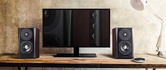
If you think that this is the end of the list of speaker design options, then you greatly underestimate the design enthusiasm of electroacoustic speakers. I described only the most popular solutions, leaving behind the scenes a close relative of the labyrinth - the transmission line, the bandpass resonator, the housing with the acoustic resistance panel, the load pipes...
Nautilus from Bowers & Wilkins is one of the most unusual, expensive and reputable speaker systems. Design type - loading pipes
This kind of exoticism is quite rare, but sometimes it materializes in a design with a truly unique sound. And sometimes not. The main thing is not to forget that masterpieces, like mediocrity, are found in all designs, no matter what the ideologists of a particular brand say.
Circles on the water
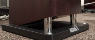
It is with this analogy that it is easiest to describe the nature of the radiation of counter-aperture acoustic systems, first developed in the Soviet Union in the 80s of the last century. The principle of operation is non-trivial: a pair of identical speakers are mounted so that their diffusers are located opposite each other in a horizontal plane and move symmetrically, either compressing or decompressing the air layer. As a result, annular air waves are created that diverge evenly in all directions. Moreover, the characteristics of these waves during their propagation are minimally distorted, and their energy decays slowly - in proportion to the distance, and not its square, as in the case of conventional speakers.
Duevel Sirius combines elements of horn and counter-aperture designs
In addition to long-range and omnidirectionality, counter-aperture systems are interesting due to their surprisingly wide vertical dispersion (about 30 degrees versus standard 4-8 degrees), as well as the absence of the Doppler effect. For speakers, it manifests itself in signal beats caused by a constant change in the distance from the sound source to the listener due to vibrations of the diffuser. True, the actual audibility of these distortions still causes a lot of controversy.
The mutual penetration of the concentric sound fields of the right and left speakers creates a very wide and uniform zone of surround perception, that is, in essence, the issue of precise positioning of the speakers relative to the listener becomes irrelevant.
Italian-Russian counter-aperture acoustics Bolzano Villetri
The other side of the coin is the great danger of early reflections of these waves from walls and furniture, the harmfulness of which I spoke in detail in the article “Basics of Acoustics for Dummies: How to Correctly Place Speakers in a Room.”
A characteristic feature of counter-aperture is that the sound coming to the listener from virtually all directions, although it creates an impressive presence effect, cannot fully convey information about the sound stage. Hence the stories from listeners about the feeling of a piano flying around the room and other wonders of virtual spaces.
Counterperture
Pros: Wide zone of spectacular surround perception, naturalistic timbres thanks to the non-trivial use of wave acoustic effects.
Cons: The acoustic space is noticeably different from the sound stage conceived when recording the phonogram.