↑ Winding products
The original output transformer on hardware from OSM-0.25 (excerpt from the article): Below is information about the transformer for the output stage on two parallel-connected 6P44S tetrodes in a triode connection. Its primary winding consists of four sections of 325 turns connected in series, for a total of 1300 turns of wire with a diameter of 0.355 mm. Each section consists of two layers with a 0.2 mm thick fluoroplastic gasket between them. The secondary winding for a 4 ohm load consists of five sections of 77 turns connected in parallel. Each section contains one layer of wire with a diameter of 0.77 mm. On top of the second and fourth sections of this winding, without spacers, two more sections are wound, each with 32 turns in two wires with a diameter of 0.56 mm (the placement of the windings is shown in Fig. 3). These sections must be wound with a gap between the turns so that the layer is evenly filled from cheek to cheek. All four wires of 32 turns are connected in parallel, and the resulting winding is connected in series with a winding of 77 turns. Thus, a winding of 109 turns is obtained for a load of 8 ohms. Between the four sections of the primary winding and the five sections of the secondary winding there are eight spacers, the thickness of which varies approximately in an arithmetic progression from 1.3 mm (first spacer) to 0.2 mm (last spacer) as the alternating component of the voltage between winding sections I and II decreases .
The author's output transformers are wound on iron from OSM-0.16 transformers and have the following winding data: I - primary winding, wire diameter 0.31mm (albeit PELSHO type wire) II - secondary winding, wire diameter 0.55mm. The number of turns in the windings, connection and sequence of sections are as in the original article. I simplified the interlayer insulation. Between the layers of the primary material there is a layer of tracing paper, between the sections there is a layer of thicker paper, such as packaging. You can experiment with the order in which the sections are turned on to obtain the widest possible gain bandwidth. Power transformer TS 180 without any rewinding. The anode supply chokes are made of iron from the DR2-LM-K television choke and wound with wire with a diameter of 0.33 mm. until the window is completely filled.
6p44s - in LUMZCH with simple anode caps
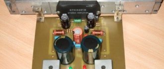
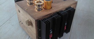
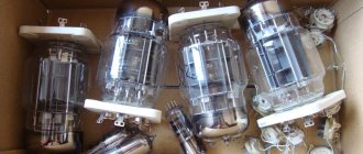
I present to the attention of television viewers another article in which the traditional incorrect presentation of the material is used. Priorities are turned upside down. First I give a description of vacuum tubes, instead of describing the features of the output transformer. We will talk about the use of 6P44S - this is a powerful electronic tube suitable for building an amplifier. It has relatively small dimensions, with a declared high power dissipation by the anode. Appearance, connection diagram, sockets and Chinese anode caps are shown in the picture. The 6P44S beam tetrode is called a television lamp. This is a very good motor for creating a high-quality two-stroke powerful sound amplifier. However, this lamp is relatively low-voltage and has a higher current compared to traditional lamps. However, a more significant feature of the output stage with these lamps is the need to use a highly efficient driver that “drives” low-sensitivity lamps.
Some inconvenience of 6P44S lamps and the like lies in the upper location of the anode terminal. In addition to the design inconveniences, there is the problem of “mining” the anode caps. Chinese caps cost a lot of money, and they are not justified by anything. I managed to make simple and reliable caps at a cost of two rubles. Ordinary ceramics from heating elements, high-temperature putty, petals made of tinned tin, MGShV 0.35 wires using HERE.
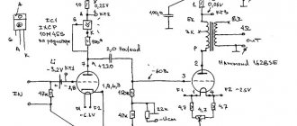
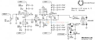
The traditional and ingrained approach to presenting material on tube amplifiers and circuits, based on the name and selection of tubes, is neither reasonable nor correct. It is unwise to start choosing a car with the engine and wheels, since first they evaluate the purpose, cost, aesthetics, functionality and other characteristics. Common sense suggests that the most important component of a tube amplifier is the output transformer. The quality of the entire amplifier depends on its quality. The cost of the output transformer can be 80% or more of the cost of the entire project. Everything depends on the choice of transformer, its manufacture or purchase, including the choice of the appropriate type of lamps. Therefore, I explain that my presentation of the material in the traditional order has a different purpose. Namely, the goal is to limit information on the use of simple and convenient standard transformers that are suitable for widely used lamps with high accuracy. If the TV viewer knew that most of the highest quality tube amplifiers could be assembled without the use of unique hand-to-hand winding manipulations, then this could perhaps collapse the tube market. And it’s very, very easy to undermine the level of artificially inflated prices for tube amplifiers using my engineering knowledge. It is the use of standard transformers in specific switching circuits that makes it possible to achieve objectively extreme sound quality of a tube amplifier. And there are no tricks here, just engineering. Moreover, most amplifiers with serial transformers can be built for colossal power. And for this you should use powerful single or double lamps of medium power in each arm of the push-pull with modified broadcast transformers or power rods. The best results are obtained by differential connection of transformers, for example according to the circuit shown below. But transformers must be selected according to symmetry conditions. Below is a diagram that I really like. In this solution there are no restrictions on gain. The fact is that 6P44S requires a good “buildup”. Therefore, the use of traditional Williamson circuitry is limited and requires additional effort when creating powerful drivers. And here cathode followers and direct connections are used. But setting up this circuit is even more complicated, and a prerequisite will be the preliminary selection of ALL lamps, and not just the output stage. The selection of double triodes according to the conditions of symmetry of the halves can be much more important than the selection of powerful lamps.
For 6P44S lamps there is another problem; it is not enough just to find a reliable description of the characteristics and modes. Although the light bulb itself is quite decent in terms of performance parameters. A particularly high supply voltage is not needed for 6P44S, but the anode current can be set quite high. Based on this, output push-pull transformers should be used with a low resistance Raa, literally a few kilo-ohms. In this option, it is quite possible to adapt some standard transformers, for example, output transformers from the Bulgarian amplifier Resprom. And of course, it is convenient to use special sectioned bourgeois output transformers with a power of about 100 W. Bourgeois sound transformers cost green money. If a single transformer is used at the output, then of course it must be sectional and symmetrical, with alternating windings, otherwise sound quality in the HF region cannot be ensured. Williamson's traditional circuit design is shown below. The output transformer is a low-impedance, ready-made Resprom one, but correctly wired into sections. In practice, most typical Resproms did not show the desired value of their own inductance. Therefore, it may be necessary to use general feedback to expand the frequency range of the amplifier in the low-frequency region.
Traditionally, it is preferable to use fairly powerful single transformers. Watt 100-160 is not bad. There must be a supply of iron. However, the use of iron from transformers of 0.4 kVA or more should be considered overkill. Transformers of this size do not justifiably increase the mass of the final product. For me, examples of the use of such transformers are, first of all, examples of illiteracy and lack of culture of the creator of a low-power tube amplifier. There are no reasonable arguments for using a 0.4 kVA output transformer in a 20-watt tube amplifier. And even more so in an amplifier designed for 5 watts. Below is a diagram that uses a pre-stage with a dynamic load. Here the tuning result will be somewhat more difficult to obtain, but with amplification the situation is better. Simpler solutions can also be used, for example in the form of an ordinary unbalanced bass reflex. To increase the amplification resource, you will have to slightly increase the anode voltage. However, in general, such a circuit should be driven from a fairly significant signal source, since the amplification will still not be enough.
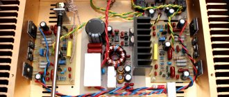
To filter pulsations along power circuits, powerful electrolytes are now used. In a push-pull amplifier, there is no need to get too carried away with increasing the filter capacity. The capacitance of the main filter capacitor is more than 1000 µF - this is generally an excessive measure. Push-pull circuits provide compensation for antiphase pulsations, so the requirements for filters are not great. However, a good capacitor may be required in the UMZCH speaker. It is better if the DC bus is formed on a powerful capacitor bank, powered directly from the rectifier. But often high-capacity air conditioners are installed after the input choke. The choice of its installation location often depends on what the viewer wants to burn with the charging current first. In addition, when constructing a power source, one must remember that a high-inductance choke simply does not allow instantaneous increased currents of peak loads to pass through and there is no need to get carried away with inductances of 5-10 henries. Contrary to science, the first capacitor of a U-shaped filter can be of relatively small capacity. This will limit the inrush current through the diodes and help save kenotrons with an exotic power supply. You should remember the general rule: high-capacity capacitors require smooth charging, subject to a strict limitation of the charging current, therefore, power supply delay units are needed, and automation is needed. As a rule, small-capacity filter capacitors are used in pre-amplifier stages. There is a negligible current consumption, so the ripples are extremely small and large capacities are not needed. However, at present it is better not to use capacitors with a capacity of less than 100 µF at all. This is junk and an outdated approach.
Below is shown a variant of the circuit with a differential pair of high symmetry matching transformers at the output. Since the transformers used are standard and of considerable power (100W each), such an amplifier can be plugged into a pair of 6P44S lamps per arm. It should be noted that the selection of paired transformers is mandatory. And setting up the amplifier has its own peculiarities, since additional measures will be needed to combat self-excitation. Much depends on the quality of installation, even a mounted one. But as a result of proper assembly, you will get a machine with about 60 W of rated power with exceptional characteristics.
The filament circuits of the output lamps can be handled more freely than the filament of the first lamps, but proper design of the housing is required. You can use paired sequential connection of 6 volt filaments. But you need to check the voltage distribution in the incandescent circuits. This will allow for lower current consumption. Therefore, the background can be reduced. It is possible to switch to direct current from stabilized or pulsed sources, or, for example, to high-frequency (28-100 kHz) power from pulsed sources. Twisted pairs for incandescent circuits must be used. But the input lamps need to be respected. The use of direct current power supply to the filaments, or the use of anode bias of the filaments gives very good results. Even better is the use of bifilar winding of special incandescent transformers. But this is a lot of work.
It is better to create an amplifier as a constructor from blocks. It is better to configure each block independently. Once assembled into a pile, you can quickly rehearse the interaction of the blocks. At the same time, you don’t have to stupidly look for a mistake that can easily be made when mounted inside a combine harvester. It should be noted that the 6P44S tetrode is rightly classified as a rather tight lamp that requires special efforts to “swing”. That’s why you should install a decent driver directly in front of the output lamps. The necessity of using 6N23P in this cascade can be justified by the ease of achieving the result, since this is a fairly powerful and dynamic lamp. But there are examples of using a 6N1P light bulb as a driver, which, with careful adjustment, can handle the tight 6P44S quite well. And the very lack of amplification of the output stage on the 6P44S can be used to its advantage when building “oak” stages with dual or triple parallel lamps in each arm. Don't forget the equalizing resistors!
The recommendation for a block approach to building a tube amplifier fully applies to the use of an output transformer. At the very beginning of amplifier manufacturing, you need to carefully test the existing transformer (transformer pair). You need to experience it separately from everything else. It must be tested using voltmeters and ammeters and load resistors when connected to the LATR. If this is a pair of transformers, then they are first assembled into a block, monolithically tied to a common plate, which is later mounted in the housing. A pair of transformers are also thoroughly tested under load. Determine the degree of symmetry, the amount of dissipation and load capacity. It’s better to immediately solder all the winding outputs with harnesses. Twisted pairs of multi-colored wire are also used. And when the transformer block is inserted into the case, the multi-colored pigtails are simply pushed through the chassis windows. The wires are formed into bundles to minimize noise and interference and the long tails are cut to the required size at the point of connection to the blocks.
The power supply is always a separate module, which is fully rehearsed and tested in advance. The amplifier's power supply is mounted into the case as intended at the very beginning, and there are no problems. The power supply produces guaranteed voltages and currents. All relay systems of the power supply must be configured in advance for time delay and maximum starting and long-term overloads. When the installation is complete, it is enough to scatter the twisted pair pigtails along the bundles and solder the ends to the terminal strips.
The result is a clear block design in which the functional purpose of all modules is clear. Setting up such a device using proven light bulbs will not be difficult. When starting up for the first time, and especially when setting up a tube amplifier, you need an oscilloscope. It becomes extremely easy to measure voltages at nodal points, as well as to catch all kinds of excitation sources. It is advisable to make your own probe with a 1:100 divider for diagnosing high voltages. The use of analog milliammeters and ammeters for monitoring currents during setup has not been canceled! This is the right approach. This method is much more cultural than using a Chinese multimeter to control the current using an indirect method based on the millivolt voltage drop across the shunt. However, the measuring instrument must have leads that are not too long, and careful installation is desirable to avoid excitation.
Evgeniy Bortnik, August 2015, Russia, Krasnoyarsk
↑ Working on bugs
When setting up the amplifier, it turned out that the background level was quite important. Since the anode supply to the channel boards was first made by separate wires from the power supply board, when connecting the screens of the input wires together and connecting them to the housing in the area of the input connector, interference increased sharply. This problem was overcome in the following way. The ground contacts at the inputs of the amplifiers of the right and left channels were connected by a thick (1mm) copper wire in an insulating tube and the anode supply terminals of both channels from the power supply were soldered approximately in the middle of the above-mentioned copper wire. As a result, the background level was reduced to an acceptable level of -60 dB ÷ -65 dB. When repeating the design, the author recommends powering the filaments of the input lamps of both channels from a separate winding, or, even better, with constant voltage. As mentioned above, the author returned to using 6N23P tubes in the first cascade, as they gave a softer, more noble sound. It also makes sense to try using transition capacitors C1, C5, C6 of other types. Much has been written about this on various relevant forums.
Practical circuits of tube amplifiers using TN transformers
Scheme 1. Two-tube amplifier using 6F3P or 6F5P triode-pentodes.
The scheme is classical and does not require a detailed description of the physics of its operation.
A differential stage is used as a preliminary amplification stage and bass reflex. The anode current of each triode is 1.45 mA. In this case, the gain of the cascade from the input to each output is 25. The sensitivity of the amplifier from the input, at maximum output power, is 0.45 volts effective value.
The amplifier output stage operates with automatic bias in class AB mode. The current balance of the output lamps is established by a small (plus/minus 1.5 volts) change in their grid biases.
The power supply is made on the basis of standard TAN transformers with a bridge semiconductor rectifier and a classic U-shaped CLC filter. For low-voltage “current” lamps, the use of semiconductor diodes in the rectifier instead of kenotrons is preferable.
Since the circuits of both the preliminary and output stages are symmetrical, there is no need for a positive bias of the filament circuit relative to the cathode to reduce the background. However, if you want to further reduce the background, such a bias can be organized by introducing into the circuit an additional resistor with a nominal value of 300 kilo-ohms and a power of 0.5 watts, connecting the lamp filament circuit to the anode supply point of the preliminary stage (+ 210 v). Then, with the existing 100 kilohm resistor grounding the filament circuit potential, a voltage divider will be formed, and the lamp filament circuit potential will be + 52 volts. Thus, the parasitic filament-cathode diode, through which the alternating component of the background current enters the cathode circuit of the lamp, will be locked in the preliminary stage with a bias of minus 32 volts, and in the output stage with a bias of minus 36 volts.
The amplifier parameters for this circuit are given in the first two lines of Table 4.
Replacing 6F3P with 6F5P will not lead to a change in the circuit, except that you will have to re-solder the wiring of the panels and turn on the windings of the output transformer. It is also possible to use “single” pentodes 6P18P, 6P43P in this circuit, and perform the differential stage of the phase inverter on a double triode 6N23P. Such a diagram is shown in the following figure. Here, a different series of supply transformers is used and the prestage is set to twice the anode supply voltage for better linearity.
Scheme 2. Three-tube amplifier for 6N23P and 6P43P or 6P18P.
The circuit is completely similar to the previous one, with the only difference that the preliminary differential stage is made on a 6N23P double triode. The anode current of each triode is 6.25 mA. The gain of such a circuit from the input to each of the paraphase outputs is 14. Accordingly, the sensitivity of the amplifier from the input, at maximum output power, is 0.8 volts effective value.
If you want to supply a paraphase input signal to the amplifiers according to Schemes 1 and 2, you need to apply an inverse signal to the grid of the second triode through the capacitor available in the circuit (0.47 μF) by disconnecting its lower terminal in the circuit from the common bus. In this case, the sensitivity of the amplifier for each input will be 2 x 0.4 volts. In Scheme 1, the sensitivity of the amplifier with a paraphase signal will be 2 x 0.225 volts.
The power supply in its constituent elements is completely similar to the previous circuit, however, the physics of its operation is different. The prestage is fed with an increased voltage of + 370 volts from the bridge rectifier to provide greater gain linearity and better circuit symmetry due to the large value of the resistor in the common cathode circuit and, accordingly, a large voltage drop across it (+ 70 volts). The output stage is powered by a full-wave rectifier formed by two bridge diodes with grounded anodes, and a potential of +200 volts is drawn from the midpoint of the anode winding. The anti-aliasing filter is similar to the previous scheme.
Frequency range at half power (0.707 voltage) from 40 Hz to 25 KHz. The sensitivity of the amplifier at maximum output power is 0.25. 0.3 volts. The variable parameters of the amplifiers according to schemes 1 and 2 are summarized in Table 4.
| Lamps | Output tr-r. | Power tr-r. | Pout [W] | Raa [Ohm] | Ea [V] | Iao [mA] | - Eg1 [V] | Rk [Ohm] | Rc [Ohm] |
| 6F3P | TN33, 36 | TAN2, 14, 28, 42 | 9 | 5000 | 220 | 2 x 32 | 16 | 270 | 240 |
| 6F5P | TN36, 39 | TAN2, 14, 28, 42 | 14 | 4050 | 220 | 2 x 40 | 20 | 120 | 270 |
| 6P18P | TN36, 39 | TAN4, 17, 31, 45 | 9 | 5600 | 200 | 2 x 60 | 11 | 330 | 75 |
| 6P43P | TN36, 39 | TAN4, 17, 31, 45 | 15 | 3333 | 200 | 2 x 60 | 16 | 330 | 130 |
Scheme 3. Push-pull ULF on “television” lamps.
The preamplifier in this circuit is made of two stages. The mode of the first amplification stage on the triode part of the 6F1P was chosen close to the standard one with an anode current of 10 mA and an anode voltage of 93 volts. Stage gain 7.
↑ Files
Additional files in CorelDraw format: 2x6P44S_SE_v2.cdr - amplifier board 2x6P44S_SE_Power_v3.cdr - power supply board 2x6P44S_SE_PowerConsole_v2.cdr - scan of the console on which the chokes and power supply board are mounted 2x6P44S_SE.spl - amplifier circuit in Splan program format