In the article “Preamplifier with Hi-End Claims!” we presented the design of Douglas Self, which had very high performance and rich functionality.
But, judging by the feedback from our readers, balanced inputs and outputs, so popular in professional equipment, are less in demand among radio amateurs. And the tone control is not held in high esteem by audiophiles. In addition, Douglas Self tried to obtain ultra-low noise and distortion levels using accessible and cheap components. Because of this, the design turned out to be relatively complex.
Today, new generation microcircuits, which have much better characteristics, have become quite accessible to radio amateurs, which makes it possible to significantly simplify the circuit without deteriorating its parameters.
Introducing a preamplifier designed by Peter Smith.
Discrete or integral.
Initially, the idea was to make an amplifier operating in class “A” using discrete elements, believing that this was the best way to obtain minimal distortion and noise values. However, due to the large number of elements, such a design may be difficult to replicate, and it will be significantly larger in size than designs using operational amplifiers, which means it will be more sensitive to external noise and interference.
The typical and still popular operational amplifiers NE5534 and LM833 were also not suitable, since today their parameters are not high enough.
More modern, inexpensive and affordable op-amps of the Burr-Brown (Texas Instruments) OPA134 series allow you to obtain a distortion level of 0.00008% at a frequency of 1 kHz! This is more than an order of magnitude (25 times) better than the parameters of the operational amplifiers mentioned above. By the way, the output stages of these op-amps do not operate in class A mode, despite their excellent linearity. The manufacturer's documentation does not reveal the secret of how these impressive results were achieved.
It was decided to use these microcircuits in the design.
Pre-amplifier specifications:
- Frequency range (absolutely flat) 10 Hz - 20 kHz,
- Maximum input signal…………………………2.9V RMS (9.5V RMS output)
- Input impedance………………………………………………………~90 kOhm
- Output impedance……………………………………………………………..100 Ohm
- Harmonic distortion…………………………………. <0.0005%
- Signal/noise…………………………………………………………… -102 dB
- Channel separation……………….. -96 dB at 1 kHz, -73 dB at 10 kHz
- Penetration between inputs. . -110 dB at 1 kHz, -93 dB at 10 kHz
Attention! The declared characteristics can only be obtained if all the authors’ recommendations regarding the selection of elements, installation and design features of the amplifier are followed.
You can compare the characteristics of this preamplifier with Douglas Self's version.
Listening to the amplifier
According to subjective sensations, the sound is simply sensational. Powerful stable bass, beautiful midrange and thin transparent highs. Since the heatsinks are not the largest, even average volume for long periods of listening causes them to become noticeably warmer.
In general, when it comes to radiators, their disadvantage is not only that they are too small, but also that each transistor is located on a separate plate. The power transistors and the quiescent current compensation transistor must be on the same heatsink and therefore have the same temperature to compensate for changes in their parameters due to heat. You can use BD139 as a transistor to stabilize the quiescent current - it will be easier to attach it to the radiator.
The maximum power is 150 W - but this is the limit. Here 100 W can be taken as long-lasting. At 2x38V the approximate power is 2x50W/8 ohms per channel. It also depends on the power amplifier itself (voltage level control). At 2x30 V at load we remove 2 x 25 W / 8 Ohms.
Functional.
The first challenge when designing a preamplifier involves the input switcher. It is believed that less distortion is obtained when using a flip switch. But, if you place the switch on the front panel, then long conductors will go from the input connectors installed on the rear panel of the amplifier to the switch, which will worsen the noise level. If the switch is located closer to the rear wall of the amplifier, a mechanical extension will be required for switching. This will complicate the design and make it impossible to use the remote control.
Therefore, it was decided to use high-quality electro-mechanical relays in the input switch. Using a separate relay for each input will result in minimal crosstalk and noise.
We also decided to equip the preamp with a headphone amplifier module. Typically, for headphone listening, a (main) power amplifier is used. But why use a powerful device if you only need a few milliWatts?
In our design, the headphone amplifier is made as a separate module (installed as desired), and the preamplifier output is switched to it using a relay.
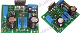
Installing the TDA7294 chip
Depending on the chip used, a jumper is installed on the board in the desired position.
Installing the TDA7294 or TDA7293 jumper
If the jumper is set to TDA7293, the empty square pad labeled TDA7294 can be filled with solder.
Filling the pad
It will be very, very little, but better.
The chip must be installed on a radiator with an area of at least 700 square centimeters. When installing the microcircuit on a radiator, you must use thermal paste. The radiator must be freely cooled by air.
Important! The housing of the microcircuit is connected to the minus of the power supply, therefore, in order to avoid a short circuit of the power source, you must either install the microcircuit through an insulating gasket (and isolate the screw that secures the microcircuit to the radiator), or reliably isolate the radiator from the housing.
In the first version, the microcircuit is cooled a little worse. In the second, it is possible to accidentally short-circuit an energized radiator to the housing.
Do what is most convenient for you.
Several microcircuits can be installed on one radiator, and the area of the radiator can be increased by as many times as the number of microcircuits installed on it. But the power wires must be suitable for each of the amplifier boards . You cannot “pass power” from one microcircuit to another through a radiator! The fact that the microcircuit's flange is connected to the power supply negative does not mean that the microcircuit can receive power through its flange!
You can attach the board to the radiator simply by screwing the chip to it. This method is applicable if the board does not use heavy exotic components and if there is no vibration during operation of the amplifier. An example of such board mounting in the amplifier case is shown on the Four-channel amplifier page.
The board dimensions and connection dimensions are shown in the figure. The flange of the microcircuit protrudes beyond the dimensions of the board by 1...2 millimeters, depending on how the microcircuit is oriented during soldering.
For more reliable fastening, you can use a special mounting hole for a screw with an M3 thread. This hole is isolated from the circuit.
The principle of using this hole is quite simple, the main thing is that nothing closes.
Mounting idea
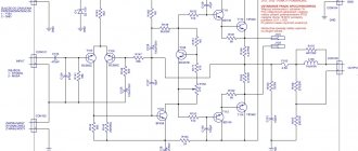
Schematic diagram
The preamplifier consists of two identical channels. All diagrams will show the left channel. In addition, the circuit is divided into two sections: the input switch and the amplifier itself.
Schematic diagram of the input switch:
Click to enlarge
The design provides 5 RCA inputs for connecting various devices. They are labeled “CD”, “DVD” and “TAPE” (of course you can call them your own). The sixth connector (CON13) is used for direct transmission of the signal from the selected input. This function was seen in industrial devices and was relevant in the era of magnetic recording. Maybe it will be useful to someone today.
The switch relays are controlled by transistors and powered from a +5V source. The common wire (ground) of this source is not connected to the common wire of the power supply of the pre-amplifier itself (they have different symbols in the diagram). This is done to reduce switching interference.
The relays are activated when the base of the control transistor is connected to the common wire. In the simplest case, you can use a biscuit switch for control.
Click to enlarge
The diagram also shows relays RLY6 and RLY7 and their control circuits. They serve to switch the output signal of the amplifier, but we will talk about this later.
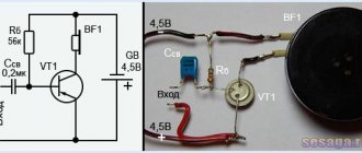
Circuit of a simple microphone preamplifier using one transistor
This microphone preamplifier circuit works with both dynamic and electret microphones.
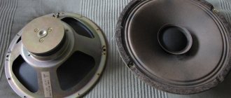
Dynamic microphones are similar in design to loudspeakers. The acoustic wave affects the membrane and the acoustic coil attached to it. When the membrane oscillates, an electric current is generated in a coil exposed to the magnetic field of a permanent magnet.
The operation of electret microphones is based on the ability of certain types of materials with increased dielectric constant (electrets) to change the surface charge under the influence of an acoustic wave. This type of microphone differs from dynamic microphones in its high input impedance.
When using an electret microphone, to bias the voltage on the microphone, it is necessary to set the resistance R1
single transistor microphone amplifier
Since this microphone amplifier circuit is for a dynamic microphone, when using an electrodynamic microphone, its resistance should be in the range from 200 to 600 Ohms. In this case, capacitor C1 must be set to 10 μF. If it is an electrolytic capacitor, then its positive terminal must be connected towards the transistor.
Power is supplied from the crown battery or from a stabilized power source. Although it is better to use a battery to eliminate noise. The BC547 bipolar transistor can be replaced with the domestic KT3102. Electrolytic capacitors for a voltage of 16 volts. To prevent interference, connect the preamplifier to the signal source and to the amplifier input using a shielded wire. If you need further powerful sound amplification, you can build an amplifier using the TDA2030 chip.
Reinforcing part
The main gain in the circuit is provided by two dual Burr-Brown OPA2134 op-amps (IC1 and IC2).
Click to enlarge
The audio signal from the selected source is input to the first operational amplifier (IC1a). A simple low-pass filter formed by a 1.2 kΩ resistor and a 56 pF capacitor attenuates the RF at the input of the op amp. A relatively large resistor value can be used here due to the extremely high (10 TeraOhm) input impedance of the OPA2134 (the input circuit is implemented using FETs).
The voltage gain of this stage is about 3.3 (10.5 dB) and is determined by the resistor values in the feedback circuit (4.7 kOhm and 2 kOhm).
The 4.7 kOhm resistor together with the 220 pF capacitor form a frequency correction circuit to increase the stability of the amplifier over the entire frequency range.
The signal from the output of IC1a (op-amp pin 1) is fed through a 22 µF non-polar capacitor to the volume control. They are used by a variable resistor with a nominal value of 10 kOhm.
From the output (slider) of the volume control, the signal, also through a non-polar capacitor, goes to the input of the second stage (IC1b). Thanks to the use of capacitors, unpleasant rustling and crackling noises when adjusting the volume are eliminated.
The second op-amp is used as a unity gain buffer, allowing the amplifier to operate reliably with any low-impedance load, regardless of volume level.
The output of the op amp is connected to the output connectors through a non-polar capacitor, a 100 ohm resistor and a ferrite bead. This makes the amplifier output insensitive to the capacitance of the interconnect cable, the input impedance of the power amplifier, and protects against radio interference that can penetrate the amplifier input through feedback circuits.
A selection of preamps for DIY audio projects from Aliexpress
Today's one is about preamp boards for homemade audio power amplifiers. A preamplifier is needed if the main amplifier has a low gain, and it also adds convenience to the operation of the main amplifier. There is an integrated tone block, input selector, remote control, etc.
Let's look at several popular options for pre-amplifier boards (analog and digital) on the AliExpress site from sellers with a large number of orders.
AIYIMA A1
Find out the price
The selection opens with a simple schematic and inexpensive option from AIYIMA. Pre-amplifier A1 is built on a pair of NE5532 op-amps. The operational amplifiers are installed in “beds” and, if necessary, can be easily replaced with higher quality ones.
Dimensions of the assembled board: 92x50x28 mm. Textolite 1.6 mm. Device power: 12-25 V AC with midpoint. There is an indicator LED. Signal input and output and power supply are organized on screw terminals.
WEILIANG AUDIO
Find out the price
Next, a similar version of the pre-amplifier with an integrated variable resistor for adjusting the volume level. Here, by the way, is a “variable” from Alps, model 27. Or you can choose the option without a variable resistor.
The preamplifier is built on a single NE5532 op-amp (replaceable) with a metal shield. Power supply of the circuit is 12-18 V AC with a midpoint.
The board size is small: 70x64 mm.
HEI
Find out the price Option for 2 op-amps
Another very budget option “pre” on one NE5532 op amp, but there is no volume control, but a convenient 12-35 V DC power supply.
The NE5532 op-amp can be replaced with any (higher quality) one in a DIP8 package. Wiring connections are organized on terminal blocks.
The board is compact (50x40 mm), easy to integrate into any audio project. There is an option for a pair of op-amps.
SURE AA-AB41148
Find out the price
Digital version of the preamplifier with remote volume control via an encoder from Sure Electronics. High-quality components, convenient connections on different types of connectors.
The gain and volume are controlled by the PGA2311 chip (THD+N: 0.0006%), adjustable from -95.5 to 10 dB in 1.5 dB steps.
Device power supply 8-15 V DC. The main board measures 122 x 91.6 mm and the encoder board measures 51 x 38.2 mm.
YJ PGA2311
Find out the price
Another digital option on the PGA2311 chip. Here the implementation from YJ includes an input selector (3 pcs.), a volume control on a push encoder and a fairly large screen (128x64). A mini remote control is also included.
The preamplifier consists of three parts connected by cables: the main board with a relay input selector (102x55 mm), a board with a screen (75x46 mm) and an encoder for control.
The device's power supply is variable with a midpoint of 6-10 V.
AIYIMA LC75342
Find out the price
A similar block version of a preamplifier with a remote control. But this option from AIYIMA is built on the LC75342 chip from SANYO. Volume adjustment -79 to +20 dB in 2 dB steps. It also has a built-in tone block. Gain 30 dB.
This implementation has a small screen (1602) and a 4-input selector on RCA connectors. There is a settings memory.
The device is powered by an alternating voltage of 12-15 V with a midpoint.
GZLOZONE NJW1194
Find out the price
A set from GZLOZONE with volume control on a high-quality NJW1194 chip (THD 0.0015%). Adjustment range: -80 +20 dB. As well as a HF and LF tone block of 10 dB. The lot has a choice: a kit for assembly or ready-made boards. A small but stylish remote control is included.
The dimensions of the main board are only 68x68 mm. Four inputs are connected there, and there is a selector. Power supply 9-0-9 V AC. Control of two encoders, two-section display.
A8
Find out the price
Rounding out the selection is a classic analogue preamp with tone controls. The A8 model is built on three JRC5532 op-amps (replaceable). The volume is controlled by a variable resistor ALPS27, there is even a power switch. In general, high-quality components were selected.
Tone control in three bands: LF-MF-HF.
Board dimensions 270x60 mm, power supply 12-18 V AC with a midpoint.
I hope the selection of pre-amplifier boards was useful and you will choose an option to suit your taste and budget.
Happy shopping! Don't forget to apply AliExpress coupons and discounts.
Impedance matching
As mentioned, the second op amp IC1b is configured for unity gain, so its output (pin 7) must be connected to its inverting input (pin 6). Nevertheless, resistor R1 is shown in the OOS circuit. To reduce distortion, the “apparent” resistance at the inverting and non-inverting inputs must be equal. However, a volume control is connected to one input, the resistance of which varies.
If you install a jumper instead of R1, the distortion level will still be very low, see the characteristics graphs. If you want to minimize distortion as much as possible, measure the resistance of the volume control in the position in which you listen to music most often and install resistors R1 (R2) with this value.
Of course, to do this, you will first need to install jumpers and conduct some test listening on your path and after that... there is a suspicion that you will not want to change jumpers to resistances.
Switching output circuits
The design allows the preamplifier output to be switched between the RCA output connectors on the rear panel of the design and the terminal block (CON6), which is designed to connect a headphone amplifier.
Two relays (RLY6 and RLY7) unused outputs are connected to ground. The relays are controlled by contacts located inside the headphone jack. Therefore, switching occurs automatically when the headphone plug is connected.
A diode, capacitor and resistors are included in the base circuit of the control transistor Q6 to delay relay switching to eliminate unpleasant clicks during switching.
Power supply
To achieve the high stated performance, we have developed a low noise power supply for the preamplifier.
Click to enlarge
It provides stabilized output voltages of ±15V and +5V for the preamp itself and additional blocks. The block board is connected to a transformer with an AC output voltage of ~15V (two windings). A diode bridge (D1-D4) and two 2200uF capacitors rectify and filter the AC voltage and provide approximately ±21V DC voltage. The LM317 and LM337 adjustable regulators provide an output of ±15 V thanks to the 100 Ohm and 1.1 kOhm resistors connected to the “OUT” and “ADJ” pins.
We used adjustable regulators because their control "ADJ" pins can be lifted off ground to improve ripple rejection, which we did using 10uF capacitors. Protection diodes (D5 and D7) provide a discharge path for the capacitors if the output is accidentally shorted to ground.
Two diodes (D6 and D8) in reverse connection protect the output of each arm in case of failure of the other.
Fixed output voltage regulator 7805 (REG3) is used to obtain +5V voltage. A 100 Ohm resistor is used to reduce power dissipation on the stabilizer chip. This resistor is not so important for the pre-amplifier module, but it will significantly ease the thermal regime of the stabilizer when connecting additional units.
Since additional power of only positive polarity is consumed from the +5V power supply, to balance the rectifier arms, a 330 Ohm resistor is included in the negative arm, which ensures the same discharge rate of the filter capacitors when turned off.
To be continued…
Happy creativity!
The article was prepared based on materials from the magazine “Practical Electronics Every Day.” Free translation of the article - Editor-in-Chief of RadioGazeta.