This is my most ambitious project, which I was terribly pleased with.
And it was like this. One day I needed an amplifier, a fairly powerful amplifier, and I came across an article from Interlavka. I assembled this device, it worked, but it was terribly unstable. The amplifier's quiescent current was far beyond normal limits, the outputs got very hot, although all other parameters were normal. Due to the lack of an oscilloscope, I had to put this whole thing aside. After this, about a month passed, but the need for an amplifier did not disappear. That's when I decided to build a four-channel amplifier. I chose the TDA7294+2sc5200+2sa1943 circuit, since I already had outputs, and one of the channels was already assembled. And the assembly began.
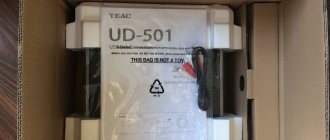
↑ Then I started working on the converter
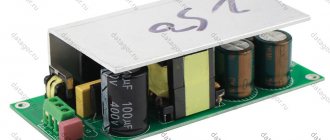
Since the amplifier is quite powerful, and there was already one converter, I decided to build a second one, albeit from what I had. So, it cost me a symbolic amount. The circuit and signet of the converter have proven themselves well, I have already assembled about 6 pieces using it, and they all work great. A detailed description and seal are attached below, I can add from myself that the transformer is wound on a 2000 nm ring measuring 45x28x12.
I have two primary coils wound in 6 turns each with 1mm wire in 4 cores. Two secondary coils are wound with 2 mm wire, 12 turns each. At the converter output +-36V with input 12V, when amplifiers are connected, the voltage drops to +-34V.
Fragment excluded. The full version is available to patrons and full members of the community.
↑ How I warmed the TL in winter
I used the TL with the CN index, which indicates the operating temperature from 0 to 70 degrees. This did not exactly make me happy, since at sub-zero temperatures the converter refused to work, and we simply cannot find TLok with the IN index, which operate from -25 to 85 degrees. And then I decided to go a different way, I found a garland in which there are 6V bulbs, soldered two in series and glued them with super glue with a gap to the TL-ka, after this modification the backlight appeared in the amplifier, and in cold weather the amplifier works fine.
Characteristics
First, let's look at the maximum technical characteristics of the 2SC5200:
- operating temperature range Tstg – 55 ... 150°C;
- maximum power dissipated on the collector RS (Pk max) – 150 W;
- the highest voltage between the emitter and the base is the maximum possible VEBO (Ueb max) - 5 V;
- the highest possible direct collector current IC (Iк max) –15 A;
- maximum current through the base IB (IB max) – 1.5 A;
- maximum permissible voltage between collector-emitter VCEO (Uke max) –230 V;
- the maximum possible voltage between the collector and the base VCBO (Ukb max) is 230 V;
- the maximum permissible transition temperature is 150°C.
All the above values are the maximum capabilities of this transistor; at these values it can operate for a short period of time. Under normal conditions, the load should be 30% less than the maximum for long and stable operation of the device.
Don't forget about the electrical characteristics as well. The capabilities of the transistor depend on them. They are removed at a temperature of +25°C. Other parameters important for testing are shown in the table in a separate column called “Measurement modes”.
| Electrical characteristics of transistor 2SC5200 (at T = +25 o C) | |||||||
| Options | Measurement Modes | Designation | min | typ | max | Unit change | |
| Collector-emitter breakdown voltage | IC = 5 mA, IE = 0 | V(BR)CBO | 230 | IN | |||
| Collector-emitter breakdown voltage | IC=10 mA, RВE= ∞ | V(BR)CEO | 230 | IN | |||
| Emitter-base breakdown voltage | IE= 5 mA, IC= 0 | V(BR)EBO | 5 | IN | |||
| Reverse collector current | VCBO= 230 V, IE = 0 | ICBO | 5,0 | mA | |||
| Emitter reverse current | VEB= 5 V, IC = 0 | IEBO | 5,0 | mA | |||
| Static current transfer coefficient | VCE = 5 V, IC = 1 A | hFE1 | 55 | 160 | |||
| VCE=5V, IC= 7 A | hFE2 | 35 | 60 | ||||
| Collector-emitter saturation voltage | IC=8 A, IB=0.8 A | VCE(sat) | 0,4 | 3 | IN | ||
| Base-emitter saturation voltage | VCE =5 V, IC=7 A | V BE(on) | 1,0 | 1,5 | IN | ||
| Current transfer coefficient cut-off frequency | VCE=5V, IC= 1 A, | fT | 30 | MHz | |||
| Output capacitance | VCB=10 V, f=1 MHz | Сob | 200 | pF | |||
| Thermal resistance between die and case | RθJC | 0,83 | OS/W | ||||
Also, all 2SC5200 can be divided into two groups depending on the gain.
| R | O | |
| hFE1 | 55 … 110 | 80 … 160 |
↑ Next there was a question with filters
I wanted to do this option: buy a 3-position switch for each channel.
The first position (switch in the extreme left position), the amplifier reproduces everything up to 100Hz. The second position (switch in the middle position), the amplifier reproduces the entire signal. Third position (switch in the extreme right position), the amplifier reproduces everything from 200Hz. Fragment excluded. The full version is available to patrons and full members of the community.
I made a filter that cuts off everything below 200Hz from one 0.047uF capacitor (k73-15A) for each channel.
Well, in the end, all that remains is to make the housing and the REM (control) function.
Manufacturers
Below is a list of manufacturers of the 2SC5200 transistor and their datasheet:
- Fairchild Semiconductor;
- STMicroelectronics;
- New Jersey Semi-Conductor Products;
- Jiangsu Changjiang Electronics Technology;
- Thinki Semiconductor.
On sale in Russia you can most often find products manufactured by the company
- Toshiba Semiconductor;
- ON Semiconductor;
- Unisonic Technologies.
↑ Housing
made from an aluminum sheet 1mm thick and 22x50cm in size. Before I used it, this sheet looked like a minibus number plate. She got it this way: my brother was traveling with friends in a minibus, the minibus driver was seriously and unreasonably rude, so they stole it. I had a hard time with this sign, cleaning it off the stickers, it took about 2 days. Then he began to bend, bending it with the help of a 4x4cm metal corner and a rubber hammer. First, I bent it with my hands, pressing the corner of the aluminum to the floor. Then he tapped the corners of the body on it.
The result was a body with the following dimensions: bottom - 30x22cm, height - 4.1cm, upper parts were 10x22cm.
Then I screwed 10x10mm aluminum blocks into the corners of the body, to which the front and rear walls will be attached. Fragment excluded. The full version is available to patrons and full members of the community.
The entire body was painted with matte spray paint.
. All transistors and microcircuits are isolated from the housing with mica gaskets.
The walls were made of plexiglass 4mm thick, since there were no other options. In these walls, using a soldering iron and a needle, I cut out holes for all the connectors and switches. I painted the inside with matte spray paint and installed all the connectors, switches, variable resistors and LEDs. On the front wall there are: switches, RCA connectors, paired resistors of 50 kOhm category B, LEDs, red (indication of the power supply of the entire amplifier) is connected to the power input of the converter through a 1 kOhm 0.25 W resistor, two green (indication of the operation of the converters) are connected to the outputs of the converters on positive arm through 3kOhm 0.25W resistors.
On the back wall there are connectors for connecting speakers (not the best option for connectors for a car amplifier), a connector for connecting power (this device was supposed to be used as a three-piece, but I used it in this design), and also two connectors for fuses on the back.
These walls are attached to the body with two large bolts, which are screwed into the blocks at the corners, as well as with 4 small bolts screwed directly into the plexiglass (the threads in it were cut with a 1.2mm tap).
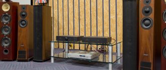
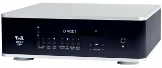
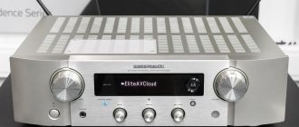
Test of Chinese amplifier Music box A1 (HDAM+Toshiba 2SC5200 and 2SA1943) $170-200
The topic of Chinese Hi-Fi amplifiers excites many, and I’m not talking about ultra-budget D-class devices for 3-5,000 rubles - you yourself understand that you won’t get too much from them for the money invested.
I have already listened to all kinds of smsl and topping in the T-class, including SA-80, etc., all this is described on the site. The layer of devices on the Chinese market of a higher level is interesting. I didn’t immediately go into very expensive models, but threw a stone into the garden of prices in the region of 170-200 dollars.
The main difference from more budget solutions is that we can no longer see microcircuit implementations, such as TDA7293, LM3886, but high-quality transistors from Toshiba, Sanken or Motorola. More often these are, of course, Toshiba and Motorola.
I was attracted by the amplifier option using Toshiba 2SC5200 and 2SA1943 transistors.
5200 and 1943 are a complementary pair. Those. one transistor is NPN type, the other is PNP.
The purpose of the transistor according to the datasheet is to create a High Fidelity class amplifier with a power of up to 100 watts:
"100-W high-fidelity audio frequency amplifier
output stage".
These are bipolar transistors.
I chose the Music box A1 amplifier in all its diversity.
It uses Toshiba 2SC5200 and 2SA1943 transistors as the output stage, but more interesting is the pre-amp stage, which emulates Maratz's HDAM system - either op-amps or a discrete assembly. This device uses an assembly based on field-effect transistors - as a result, we get a hybrid of mosfet and bipolar.
We read how the seller describes this device, he uses a comparison with an amplifier based on TDA7494 (this is a chip operating in class AB) and LM3886:
“The low frequency is softer than LM3886, the immersion is deeper, richer, there are charming high frequency overtones. The TDA7494 at 100W provides only 8A of output current, which is not enough to control complex acoustics, but a pair of 5200s have a current of 15A.”
Regarding control, yes, the amplifier really has control, but about soft and deep low frequencies - this is rather fantastic. In the lower register, the amplifier is quite modest.
Read the description below:
“The circuit uses a classic Marantz HDAM field stage, combined with Toshiba 2SC5200 and 2SA1943 transistors, the timbre is very warm and charming, the lows give good immersion, the overtones are rich.”
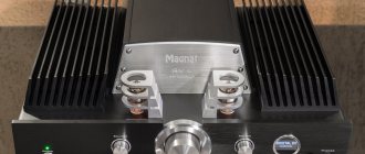
We're intrigued, but let's return to the design of the amplifier.
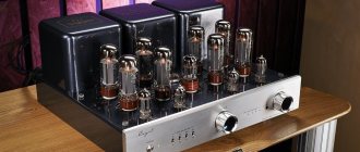
So, it uses Marantz's simulated HDAM system as the input stage and bipolar power transistors at the output. The Japanese Omron protective relay is also used. A rather large and heavy torus-shaped transformer is responsible for powering the device.
The stated maximum power is 65 watts per channel, i.e. quite enough for home listening.
The rather thick aluminum case is used as a heatsink for transistors. Alps Volume Control - I noticed some play in the knob on this, but it doesn't have any negative impact on listening or volume control. I disassembled the device - but inside all the elements are rigidly fixed - you can see this peculiarity of fastening the handle itself.
The device weighs 4 kg and given its small size of 240 x 160 x 55 mm, it is quite heavy.
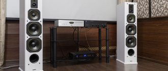
Of the controls, only the volume knob is available, which is enough for any Hi-Fi class device. The power button is located on the side of the amplifier. At the back there are connectors for connecting acoustics - large knobs with imitation gold plated and RCA connectors for the left and right channels, similarly with imitation gold plated.
Having started listening to the amplifier in my system, I noticed that it was difficult for me to determine its place in the line of devices.
I connected it to a fairly high-level path, which should exceed the capabilities of this amplifier and show exactly its capabilities - a shelf-mounted and fairly heavy-load speaker Onkyo D-302e (4 Ohms, 83 dB) and a DAC on Saber ES9018 + 2 Muses8920 + 2 AD797 + two transformers.
Overall, based on the listening results, the device is very smooth. The lower register is modest, it lacks a little depth, but this is not a particularly important point. Mids and highs are neat. The resolution is high enough for listening. I found it extremely difficult to classify it in the line of equipment, because not only could I not understand where it belonged - it sounded quite good, but too neutral, a little stingy in emotionality. It felt like a mid-level device.
But because of his neutrality, I could not give him an assessment - I liked the way he sounded, but who is his competitor, that’s the question. Therefore, I connected the Marantz PM 6001 amplifier to the same path (consider it the same as models 6002-6003-6004). It seemed to me that the Chinese amplifier would now easily surpass this good initial Marantz, but unexpectedly, in combination with the Onkyo D-302e acoustics, the Marantz PM 6001 showed previously unseen qualities - powerful emotionality, sparkling sharpness with a cool “hoarseness” on trumpets, saxophone, feelings in vocals when listening to Michael Jackson, Paul Desmond, etc.
Here the Marantz PM 6001 clearly had an advantage, although maybe a little “dirty”. The Chinese device presented everything carefully, accurately and neutrally, but there was a feeling that an emotional gray sheet had been thrown over it.
Therefore, I will classify the device in a lower category than the Marantz PM 6001, and its HDAM imitation has little relation to reality.
But nevertheless, I quite liked the Music box A1 - a good, solid device in its niche - it is a good candidate instead of microcircuit models based on TDA7494 or LM3886.
I took it in black
What I liked most was the tandem of this amplifier with the Xiangsheng DA-03a DAC via a tube output.
The characteristic features that were noted in the device are rich copper instruments, striking neutrality, and fairly high resolution.
I also tried the Music box A1 with other components - a DAC with two PCM1794s and Diatone DS-1000ZA speakers. But my impressions about this device have not changed.
I rate this experience as positive, the device is quite good despite the noted emotional stinginess, it left a good impression, so I want to try less budget models.
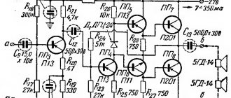
Amplifier circuit:
↑ REM function
already done in the converter, but I don’t really like it.
I switched it to constant plus, and organized REM using 2 relays (these usually come with alarms and central locks), each on its own converter and glued them to the body with superglue. I connected it like this: there are four contacts, two for power and two for power. I connected a constant plus to one power supply, and a positive to the second to power the converter. One power terminal receives a constant minus, and the second power terminal receives a plus from the REM terminal. So, when you turn on the radio, a plus appears on the relay, it turns on, and power comes to the converter. That's all, all that remains is to solder and twist everything together.
All connectors and parts were purchased in the store and on the market. So, the first turn-on ended successfully, everything works, the sound pleases with its power and clarity. I was pleased.