Transistor amplifiers
B. Khokhlov High-quality low-frequency amplifier. - Radio, 1960, No. 2, pp. 27, 28
The author describes a power amplifier using transistors P11, P13, P201 with a tone control and a stabilized power supply. The amplifier has a maximum output power of 6 W at a load of 8 Ohms, a reproducible frequency band of 30 - 20,000 Hz, frequency response unevenness - 3 dB, nonlinear distortion of no more than 5%. Subsequently, this circuit was repeated on a base of elements that was more modern for that time (usually this circuit was implemented on germanium transistors).
In the same article, the author provides a tone correction diagram:
The frequency response of this tone compensator is given below:
The power amplifier can be powered with a voltage of 12V, the output power will be 3-4 W.
Transformerless amplifier using transistors. - Radio, 1961, No. 10, pp. 57,58
Amplifier output power 2-2.5 W, reproduced frequency range 10 Hz - 20 kHz, nonlinear distortion factor 3-4%, sensitivity - 30 mV.
I. Zhuravlev, V. Belousenko On the selection of transistors for high-quality low-frequency amplifiers. - Radio, 1968, No. 2
By the beginning of 1968, the circuit of a transformerless amplifier using transistors took on the following form:
At the same time, to achieve maximum sound quality, it was noted that it was necessary to select transistors. It was noted that with a careful approach to selection, it is possible to achieve a harmonic coefficient of 0.5-0.8% with an output power of 8-15 W. The article provides a diagram and description of the methodology for selecting transistors:
Tube Amplifiers
V. Bolshov Low frequency amplifier. - Radio, 1965, No. 7
The circuit of this amplifier is very simple (contains only 2 non-scarce tubes - 6N2P, 6P14P) and can be recommended for a beginner “lamp maker”. The amplifier has an output power of 3 W, sensitivity - 100 mV, nonlinear distortion coefficient does not exceed 5%, and a reproducible frequency band of 20 - 20,000 Hz (if properly configured).
A description of the amplifier design and recommendations for its settings are given in the original article .
V. Ivanov Low frequency amplifier. - Radio, 1967, No. 8, pp. 46-48
Another diagram for beginner “lamp makers” was published in the 8th issue of Radio magazine for 1967. In addition to its simplicity, its advantages include a detailed description and recommendations for changing the circuit in terms of introducing environmental protection, which allows you to experiment with the circuit by “feeling” it from the inside.
This amplifier has an output power of 3.5 W (with the introduction of OOS it decreases to 3 W, but the range of reproduced frequencies expands), a nonlinear distortion coefficient of less than 2%, sensitivity of 100 mV, amplified frequency band of 50 - 12,000 Hz, intrinsic noise of 500 times weaker than the useful signal.
The output transformer can be either ready-made from the output stage with a 6P1P lamp or home-made on a W-shaped core with an average core area of 4 cm2. The primary winding contains 2500 turns of PEL 0.16, the secondary winding contains 75 turns of PEL 0.8-0.9.
A description of the amplifier design and recommendations for setting it up are given in the article .
V. Shlykov Economical amplifier for car receivers. - Radio, 1960, No. 5, p. 32
This tube amplifier circuit (6N2P, 6N14P) with an output power of 1 W (with an anode quiescent current of 6-8 mA) and a linear frequency response in the range of 60..9000 Hz is quite simple to repeat and can be used to build your first tube amplifier. By default, the circuit is used to connect to the receiver IF amplifier with an output voltage of 150 mV.
The output transformer is wound on an Ш12 core, the thickness of the package is 15 mm, assembled into a cover. The primary winding contains 2 x 3000 turns of PEL 0.1 wire, the secondary winding contains 72 turns of PEL 0.51 (for a speaker with a resistance of 5.5 Ohms).
V. Bolshov Low frequency amplifiers. — Radio, No. 7, pp. 47-51
The article provides several simple circuits of power amplifiers using tubes.
1. UMZCH on 6Zh1P and 6P14P has an output power of 3 W, sensitivity of 150 mV, and nonlinear distortion coefficient of 2.5%. The amplifier has a correction chain C7R6C5 for adjusting the HF tone.
Frequency response for 2 extreme positions R6
The output transformer is made on a Ш16x16 core, the primary winding contains 3500 turns of PEL 0.15 wire, the secondary winding contains 165 turns of PEL 0.64 for a load with a resistance of 4 Ohms.
2. The amplifier circuit below has the following characteristics: output power - 3 W, sensitivity - 100 mV, non-linear distortion factor - 1.5%. The amplifier is made using 6N2P tubes,
6P14P and has tone control for bass and treble.
The output transformer is similar to the previous design.
3. Below is a circuit diagram of a push-pull power amplifier. Its output power is 10 W with a harmonic distortion of 0.3%, sensitivity is 0.7 V.
The output stage of the amplifier is made according to an ultra-linear circuit and operates in AB mode. It must be taken into account that this class of amplifiers has more stringent requirements for output transformers and anode voltage filtering.
The output transformer is made on a Ш25x30 core. Sections of the primary winding Ia, Ig contain 850 turns of PEL 0.1 each, windings Ib, Ic contain 650 turns of PEL 0.1 each. The secondary winding contains 140 turns of PEL 0.64 for a load of 16 Ohms. Winding circuits for transformers for ultralinear amplifiers are given in specialized literature, also available here: Radio No. 4, 1958, p. 28.
4. The amplifier below has an output power of 12 W with a harmonic distortion at 1000 Hz - 0.4%. Amplifier sensitivity - 100 mV.
The output transformer is made on a magnetic core Ш25х30; to reduce the inductance between the windings, it is wound as follows:
The primary winding is divided into 6 parts of 500 turns of PEL 0.1. The secondary winding consists of two halves connected in series, consisting of two parallel-connected sections of 40 turns of PEL 0.64. In practice, the winding of the transformer is carried out as follows: first, sections 1-7-2-8-3 are wound, after which the frame is turned over and sections 4-9-5-10-6 are wound. Then the sections are connected according to the diagram in Figure (b).
5. The circuit of a 20-watt amplifier with a THD of 1.2% and a sensitivity of 0.5 V is shown below. The frequency response is uniform in the range 20 Hz - 20 kHz.
The output transformer is made on a Ш30x35 core. Windings Ia, Ib each contain 1200 turns of PEL 0.25, winding II contains 85 turns of PEL 1.0. Winding is carried out according to the rules for ultralinear UMZCH (see description above).
6. A two-channel tube power amplifier (4.5 W LF/KG - 3%, 3 W HF/KG - 2%, input voltage - 250 mV) is built on 3 lamps according to the following scheme:
The HF output transformer is made on a Sh12x16 core, the primary winding contains 1500 turns of 0.1 PEL, the secondary winding contains 56 turns of 0.51 PEL. The plates are assembled end-to-end with a gap of 0.1 mm. The LF output transformer is assembled on a USH 19x28 core. The primary winding contains 3000 turns of PEL 0.12, the secondary winding contains 52 turns of PEL 0.64 wire. The plates are assembled end-to-end with a gap of 0.12 mm.
V. Smirnov High-quality amplifier. - Radio, 1960, No. 9, pp. 45, 46
The author has proposed a circuit of an ultra-linear power amplifier with 5 lamps (monaural version) with an autotransformer output for a load of 4 and 16 Ohms. The use of an autotransformer simplifies the repetition of this design. The output power of the UMZCH amplifier is 12 W, the coefficient of nonlinear distortion is 3%, the sensitivity is 100 mV, the reproducible frequency band is 30...20000 Hz.
The first stage is made on a 6ZH1P high-frequency pentode to expand the amplifier's bandwidth towards HF. The second stage is a cathode follower made on “half” of a 6N1P triode. The output stage is assembled using 6P14P lamps using an anti-parallel circuit. The filter on elements R8C4R9C5 in the circuit is used to reduce interference from the electric motor of the record player - if repeated, it is not relevant at the moment.
The lamps should be powered from two transformers or from one but with insulated windings. Each rectifier must provide a current of up to 55 mA at a voltage of 250-300 V.
The output autotransformer is made on a Ш25x25 core. Sections I and I' each have 50 turns of PEL 0.9, II and II' each have 80 turns of PEL 0.9, III and III' each have 740 turns of PEL 0.31.
If you plan to use the amplifier with a different load, then the number of turns can be calculated using the formula:
A simple bass amplifier. - Radio, 1961, No. 9, p. 56
There is no separate bass reflex in the amplifier circuit; the output tubes themselves work as bass reflexes. The amplifier output power is 6 W.
Transformer Tr1 is selected with a power of 15 W, the primary winding is designed for an anode load resistance of 8 kOhm, the secondary winding for a load of 4 Ohms.
G. Krylov Modernization of a simple low-frequency amplifier. - Radio, 1962, No. 4 p. 52
The power amplifier circuit with 3 tubes (6Zh8, 6N9S, 6N5S) has a rated output power of 4 W, a reproduced frequency of 30..15000 Hz, and a nonlinear distortion coefficient of 1%.
The output transformer is assembled on a Ш-20 core, the thickness of the set is 20 mm. The first and third sections of the transformer contain 84 turns of 0.51 PE, the second - 336 turns of 0.35 PE. Winding order: First - Second - Third (see Radio, 1961, No. 1, p. 53, 54).
G. Krylov Broadband low frequency amplifier. - Radio, 1963, No. 11, pp. 37-39
Circuits of power amplifiers with a reproducible frequency band from 20 Hz to 20 kHz began to be published in USSR periodicals starting in the 60s of the 20th century. This was due to the development of broadcasting in the VHF range, which made it possible to broadcast programs in high quality.
One of the first schemes with high performance (for that time) was published in late 1963:
It should be noted that the magazine provides a detailed description of the manufacture and adjustment of the amplifier, which significantly increases the possibility of its successful repetition.
The output power of the amplifier is 7 W, the coefficient of nonlinear distortion is ~1%, the frequency of reproduced frequencies with a nonlinearity of no more than 1 dB is 20 - 20000 Hz, sensitivity is 0.2 V. The amplifier is designed to operate with a high-resistance load of ~300 Ohms. When using an autotransformer, you can also use regular 4..16 Ohm speakers.
For a 9 Ohm load, the autotransformer is made on the basis of the USH-16x32 core, winding I contains 500 turns of PEL 0.35 wire, section II - 110 turns of PEL 0.74.
Setting up the amplifier comes down to selecting the lamp mode (measured with a voltmeter with a high-impedance input of 20 MΩ/V). To ensure high amplifier performance, it is necessary to carefully select resistances R10, R17, R18, R19, R21, R22, R23 - selected in pairs for each stage with an accuracy of at least 5%.
E. Vaisman Elektrolina. - Radio, 1964, No. 8, p. 60
The amplifier circuit is taken from the general circuit of the Elektrolina electric musical instrument. The amplifier operates in ultra-linear mode, has an output power of 12 W and reproduces a frequency range from 40 to 15,000 Hz. The coefficient of dynamic distortion does not exceed 0.3%. The circuit uses an output transformer from the Festival radio receiver.
G. Krylov Low frequency amplifier. - Radio, 1966, No. 2, p. 28
The amplifier is made using 6N2P and 6S19P tubes and has a transformerless output, albeit for a high-impedance load. Connecting low-impedance speakers is possible via an autotransformer. The amplifier operates in the frequency range 20 - 20,000 Hz, has an output power of up to 3 W, and a nonlinear distortion coefficient at a power of 2 W of about 1%.
The autotransformer can be assembled on a Sh-16 core with a set thickness of 32 mm. Winding I contains 500 turns of PEL 0.33, winding II and III - 70 turns of PEL 0.51 each. Section II is wound first, then I and lastly III.
The original article can be downloaded here .
N. Zykov High-quality bass amplifier. - Radio, 1966, No. 4, 5, 6
The amplifier has an output power of 8 W, sensitivity - 100 mV - 10 V depending on the input type, nonlinear distortion coefficient at a power of 6 W - 0.2%, at maximum - 0.5%. The amplifier is designed for a load of 4 ohms and has a 5-band equalizer. The UMZCH uses: 3 6N1P lamps, 2 6P14P lamps. In fact, this circuit was the first publication of a high-quality amplifier in periodicals with a description of the design and the possibility of repetition by a radio amateur with average qualifications.
A detailed description of the design can be downloaded here .
N. Zykov Bass amplifier with expander. - Radio, 1966, No. 12
The amplifier is built on 6N2P, 6N1P tubes and has the ability to expand the dynamic range by 10 - 14 dB, which improves sound perception. The amplifier output power is 12 W, the reproduced frequency range is 30 - 18000 Hz, the sensitivity is 100 mV, the nonlinear distortion coefficient does not exceed 1%. The load can be a resistance of 1.5 - 9 Ohms.
A detailed description of the design can be downloaded here .
A. Slonim Two-channel amplifier. - Radio, 1967, No. 9, pp. 31, 54
The amplifier circuit proposed by the author has separate final amplifier stages for low frequencies (40 - 1000 Hz) and high frequencies (1000 - 15000 Hz). The amplifier is built on 4 tubes: 6Zh4 (6Zh1P), 6N9S (6N2P) and two 6N5S in the final stages. Each 6N5S can be replaced with two 6S19P. The amplifier is designed for a high-resistance load (150 - 550 ohms); a low-resistance load can also be used in conjunction with an autotransformer (see Radio, 1966, No. 2, p. 28). The amplifier sensitivity is 100 mV, output power is 3.5 W per channel.
Option for replacing output lamps with 6S19P
The description and configuration of the amplifier, as well as the power supply diagram, are given in the article .
G. Krylov Low frequency amplifier. - Radio, 1967, No. 3, p. 32
The author presents a circuit of a simple amplifier using three tubes: 6N2P in the preliminary amplification stage and 2 6P14P in the final stage. The amplifier output power is 6 W with a nonlinear distortion factor of 1%. Reproducible frequency - 30 - 15,000 Hz, sensitivity - 0.3 V.
The output transformer is made on an Ш26 core with a set thickness of 26 mm. The primary winding contains 2x1200 turns of PEV-2 0.19, the secondary winding contains 3x88 turns of PEV-2 0.47. The winding layout is shown in Fig. below:
You can read more about the amplifier
.
E. Zeldin Triode amplifier class B. - Radio, 1967, No. 4, p. 25, 26
The article presents two amplifier circuits using 6F1P and 6N6P tubes and 6N2P and 6N6P tubes. Output power 2.5 W (3 W at anode voltage 300 V), nonlinear distortion coefficient >4% (1% with the introduction of OOS). Reproducible frequency range - 40 - 15,000 Hz.
The output transformer is assembled on a Ш-12 core, the thickness of the set is 20 mm. The primary winding consists of two sections, each with 2300 turns of PEL 0.12, the secondary - 74 turns of PEL 0.74 (wound between the sections of the first winding).
For this circuit design, the output transformer is assembled on a Sh-12 core with a set thickness of 18 mm. The primary winding contains 2 sections of 1800 turns of PEL 0.13, the secondary winding contains 95 turns of PEL 0.59 for a load of 13 Ohms). The secondary one is wound in the same way as in the previous version between the sections of the first one.
A more detailed description is given here .
G. Krylov Low frequency amplifier. - Radio, 1968, No. 8, p. 41
The amplifier is built on 3 lamps (6Zh1P and 2x 6P15P) and has the following parameters: Output power 6 W with a harmonic distortion of 3% (with a power of 4 W, harmonic distortion is 1%), reproduced frequency range with unevenness of 1 dB - 25 - 16,000 Hz, sensitivity - 170 mV, noise level -55 dB.
Output transformer on a Sh-26 core with a set thickness of 26 mm. Primary winding 2x 1200 PEV-2 0.19 mm, secondary winding 3x 88 PEV-2 0.47 mm.
A. Mezherovsky Two-channel ultralinear amplifier. - Radio, 1968, No. 5, pp. 33-36
The author proposed a non-standard method for separating the LF and HF channels due to deep OOS.
The amplifier (in monophonic version) is built on tubes 6N2P .93 pieces) and 6P14P (4 pieces). It is designed for a maximum power of 7.5 W (per channel) with a maximum total harmonic distortion of no more than 0.85%. Nonlinearity of the frequency response in the range of 15 - 30,000 Hz is no more than 0.5 dB.
To calculate the secondary winding for a specific speaker, the article provides a formula.
Strict design and thoughtful filling
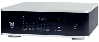
So, the A-70DA is a stereo integrated speaker with such a classic look that it will surely cause a fit of acute nostalgia in many music lovers. However, photographs do not fully reflect reality. Having met the device in person, the first thing you concentrate on is not its old-school design, but on the extraordinary quality of finishing of the entire structure as a whole and each of its elements separately.
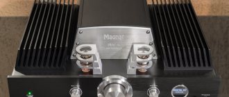
Forget about plastic handles and trim, everything here is grown-up. The sides of the case are 1.8 mm aluminum plates, and the front panel is a 3.5 mm thick milled aluminum plate. All control drums are also made of winged metal, and the volume control is so large and massive that turning it is a separate sensory pleasure.
Classics of the genre. It’s a pity that you can’t feel the weight and quality of the structure from the photo.
Nearby are the tone block knobs, which in recent years, for some reason, many developers often began to forget about. But let's not prevaricate: maybe not for audiophiles, but for music lovers there are certainly situations when it is difficult to do without direct correction of bass or treble frequencies.
The timbre block, of course, is switchable, and in addition to three standard knobs, it is equipped with a completely forgotten tone compensation button, as well as an attenuator that limits the volume control range. Why is this necessary? Well, for example, so that a child doesn’t accidentally turn the volume up to maximum, depriving the whole family of both audiophile hearing and their favorite speakers in one move.
Looking at the Pioneer A-70DA from the rear, we find two stereo sets of acoustic terminals - fans of bi-wiring should appreciate it. The pads, by the way, are quite massive and are excellent for installing large cross-section wires. There is no official information about the nature of their golden coating, but all input connectors are indeed gold-plated.
Among them were also digital inputs, including USB Type B. That is, despite the patriarchal appearance, the device is armed with an integrated DAC, and of a fairly serious level.
The output terminals allow you to use two sets of acoustics or arrange bi-wiring. Even with a really thick wire, connecting to them is not a problem.
It is built on an eight-channel ES9016 chip from ESS, part of the advanced Saber32 Ultra DAC family. The number 32 indicates the 32-bit internal architecture and the corresponding input resolution of the converter. I note that the current flagship Saber Pro line was introduced after the release of the A-70DA, so its developers honestly chose the best available at that time.
Judging by the number of DAC channels, it is easy to guess that the audio path is built according to a balanced topology, and it applies to all its structural components, with the exception of the phono stage inputs. Which, by the way, can work with both MM and MS cartridges.
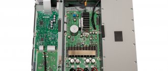
By the way, about topology. The internal space of the apparatus is divided into three sections by solid steel bulkheads. In one there is a preamplifier along with a separate linear power supply, in the second there are stages of the power amplifier, and in the third there is its powerful power supply.
In this case, both transformers are placed in additional metal boxes filled with compound and mounted on vibration absorbers. In turn, the entire internal frame rests on a massive 4.6 mm thick support platform. It is not surprising that the total weight of the structure reaches 17 kg. That is, according to the concepts of modern hi-fi, the component is simply unbearable.
Reliable screens are everywhere possible, but large radiators are not visible - pulsed heat amplifiers hardly dissipate heat
The power amplifier installed in the A-70DA operates in class D, or rather, it is made using proprietary Direct Energy circuitry. Its key element is Direct Power FET field-effect transistors.
They differ from classic MOSFETs mainly in their packaging: the semiconductor crystal is mounted directly on the contact pads of the printed circuit board. In this way, it is possible to get rid of the signal transmission through the thin terminals of the case and its passage through unnecessary connecting points.
Another important point is that the balanced preamplifier, the built-in phono preamplifier, and the output circuits of the integrated DAC are maximally optimized for working with specific pulse amplification units.
Don’t forget about the Direct and Loudness buttons, they have a very significant impact on the sound
So, we have before us a self-sufficient station wagon, which only needs to be connected to speakers on one side, and to almost any source on the other. Looking ahead a little, I will say that such a source can be not only a network player like the closely related Pioneer N-70AE, but also any laptop, or even a smartphone, if it is compatible with the USB Audio Class 2 standard. By the way, I checked - it really works .
