Contents
- 1 UPS specifications
- 2 UPS testing 2.1 Lamp load and first failure
- 2.2 Loading with resistors
- 2.3 UPS heating
- 2.4 Character of pulsations
- 2.5 Preliminary conclusion and search for application
- 4.1 Amplifier circuit
- 7.1 Cons
Weather resistance
If the concert amplifier will be used in an open area, then you should choose equipment that is not afraid of precipitation and hypothermia. In this case, we are talking about a special design of the case, which protects the contents from environmental influences.
The scope of application of a concert amplifier is very, very wide. These are, first of all, as their name suggests, various concerts and other mass public events where good and loud sound is required. You can’t do without them in sports arenas, large restaurants and other catering establishments, theaters and assembly halls. In addition, they will be in demand in shopping and entertainment centers, where sound reinforcement equipment will help create the required atmosphere that will increase purchasing power.
It should be remembered that a professional sound amplifier should be purchased either together with the purchase of the speaker system, or after it has been purchased. Moreover, it should be taken into account that the power of the speaker system must be higher than the power of the amplifier, then the latter will be impossible to damage. In addition, the amplifier should not operate at maximum power all the time - this leads to increased distortion of the audio signal, and also reduces the service life of the amplifier itself and the speaker system. In any case, no matter what you purchase - speakers and amplifiers for discos or powerful concert options for a famous artist’s tour - you can always count on receiving advice from professionals from!
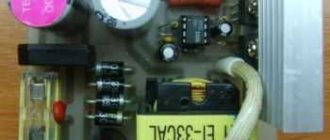
↑ UPS passport parameters
So, it is stated:
• Input voltage: ~100-265 V • Output voltage 1: +6.3 V @ 4.5 A • Output voltage 2: +250 V @ 0.15 A • Output power: 60 W • Operating frequency: 65 kHz • PCB size : 120 mm × 55 mm.
• Size of mounting holes: 112 mm × 47 mm. Already here some discrepancy is revealed.
The power from the anode source is 37.5 W and from the filament source is 28 W, which in total gives a little more than 60 W, but not significantly. When he arrives, we'll see then.
Delivery was surprisingly fast. Less than ten days had passed before I was already carrying a package with a parcel from the post office.
Specifications
However, the customer is not always given the opportunity and desire to understand the meaning of many parameters on which sound quality depends. Sound amplification equipment has a number of technical characteristics - nonlinear distortion factor, output power and input resistance, source emf and total harmonic distortion, as well as many other parameters. Therefore, the best test for the equipment will be its continuous operation for several hours at the borderline possible (70-80% of the maximum) power. Well, consultations from technical specialists are always at your service!
↑ UPS testing
Unpacked. I soldered screw terminals to the output (for some reason they were only at the 220 V input) to make it more convenient to connect the load. First, let's check what the unit outputs at idle.
The voltage of 6.3 V corresponds to the declared one. Everything is correct.
Anode voltage of 245 V is also not bad.
We will assume that the Chinese did not lie. Moreover, under load, everything can change both up and down.
↑ Lamp load and first failure
We have a power supply for a tube amplifier, so we’ll load it with tubes to test it. I connected a 40 W incandescent lamp to the anode circuit, and connected a 6P45S lamp to the incandescent output, why bother with trifles. I turn it on, and then a bummer awaited me!
The unit worked in start-stop mode. It applied the load for a second and was immediately turned off by the protection circuit. The load turned out to be too big.
I captured this trouble on video.
I wrote to the Chinese saying that your power supply is not working, what should we do? But the Chinese turned out to be a seasoned kalach and knowledgeable in electronics. He wrote to me that lamps have a much lower cold filament resistance than in nominal mode, which is why the unit works like that for me. He said that he would not accept complaints. Well, okay, I guessed about it myself.
↑ Loading with resistors
Well, let's check the unit's functionality with resistors as a load.
I loaded the filament circuit with a chain of 0.82 Ohm resistors, with a total resistance of 1.6 Ohms. I connected 2 resistors with a total resistance of 2.2 kOhm to the anode circuit. Turned it on. The launch went without problems. The output voltage immediately appeared. The anode circuit produces 117mA, the voltage on it has increased slightly compared to idle mode.
The filament circuit delivers a current of 3.8 A. The voltage dropped slightly to 6.2 V.
↑ UPS heating
The power supply practically does not heat up. The radiator is slightly warmer than your finger after 30 minutes of operation. The same cannot be said about load resistors. The table under them began to smoke.
↑ Character of pulsations
I looked at the output voltages with an oscilloscope.
Along the 6v circuit, RF interference occurs in the form of short pulses with an amplitude of about 200 mV. The same goes for the 250 V circuit. Also 200 mV. The repetition rate of these pulses is about 250 kHz. Far beyond the audio range. They shouldn't interfere with us. I tried to fight these pulsations. Increased capacitors at the input and output. I put them in more purebred ones. Nothing significant has changed.
During these experiments, it was necessary to make cutouts in the radiator to accommodate larger capacitors. The appearance of the block has changed slightly. There are practically no parameters. So there was no need to bother with this modification.
↑ Preliminary conclusion and search for application
We will assume that the power supply is operational.
All that remains is to figure out what to assemble on it.
And then the question arose, what lamps can be connected to it so that it does not go into protection when the filaments are cold. I started connecting different lamps to it and checking whether it started or not. The unit starts confidently when lamps are connected to it, consuming a nominal filament current of no more than 1.8-1.9 A according to the reference book.
For example, a pair of 6P6S lamps and a 6N8S lamp can be connected to it: 0.45A+0.45A+0.35A=1.25A in total. But a 6P45S lamp, which normally draws 2.5A in a warm state, cannot be connected. The block goes into overload. Although, as I already checked, it pulls a 3.8A resistive load without straining.
Studio amplifier
What are the main characteristics of a studio amplifier?
- It has a much larger frequency range - from 10 Hz to 100 kHz, while the household version operates in the range from 20 Hz to 20 kHz;
- In those amplifiers that are purchased for work in the studio, you will not find a tone control, so you should think about purchasing an additional mixing console;
- It is possible to adjust the volume of the channels separately, whereas in household amplifiers one control is used for both channels and a balance control;
- In the manufacture of individual elements, higher quality materials are used and higher requirements are placed on the level of assembly. This applies to all connectors, protection against short circuits, overloads and other force majeure circumstances. Accordingly, professional amplifiers are more reliable.
↑ Datagor projects to which this UPS is suitable
• Simple tube amplifier 6N1P + 6P14P.
Beginner's Assembly • Small-sized SRPP tube headphone amplifier. Printed circuit boards, backlight, housing • Tube amplifier “Pokemon”: 6N23P + 6P14P on one board and in a thin case • Amplifier with 6N2P + 6P14P. Simple, tube, guitar • Tube amplifier for high-impedance headphones on 6N6P • Tube five-band graphic equalizer in a slim case, 6N2P+6N1P • “Pokemon” by Oleg Chernyshev as the first tube amplifier • The story of how the SRPP amplifier was turned out of a lunch box construction kit for headphones • Tube preamplifier RIAA-phono stage. First experience • Headphone amplifier: SRPP on 6N6P • Tube amplifier SRPP on 6N23P for headphones in a housing from an external HDD • My first SRPP headphone amplifier • Tube amplifier “D'n'B Warrior”. SRPP 6N23P for headphones with a switching power supply on IR2153 • Universal tube pre-amplifier on 6N23P • Step-by-step instructions for mounting a MAI tube amplifier on 6F3P for beginners • Tube UMZCH on 6N3P+6P14P? It's simple! Printed circuit board included • 32 Ohm tube headphone amplifier PHILLIPS SHP1900. Project VINTAGE • Headphone amplifier based on 6n3p and 6n24p tubes (White cathode follower) on HI-END components • Tube AMPLIFIER on 6F3P FOR BEGINNERS FROM BEGINNERS • My experience in creating a tube amplifier on 6P9 • Entry-level tube amplifier on 6F3P, 6F5P • Tube Baby on 6N16B and 6P30B • Tube amplifier for a computer on 6F3P [Updated] • Real transformerless tube amplifier for low-impedance headphones based on “Laconic” • Simple tube amplifier SRPP for headphones without an output transformer • My tube SE on 6F3P (ECL82) according to A. Manakov And other articles. Watch, try, create!
Input selector
I implemented it on one of the most interesting projects. It has four line inputs and one output. There are plans to add an additional input for the platform in the future. The signal from any input stops at the relay until the selector switch sends a signal to the CD4017 chip, which, in turn, controls the transistors and the voltage on the coil of that relay. The signal then goes to the preamplifier and the power amplifier. This circuit also has a separate power supply, like the preamplifier.
↑ Test by practice. A simple single-ended amplifier using 6N9S and 6BD5 tubes
After thinking a little, I decided to use this power supply to make a simple single-ended amplifier using 6H9C and 6BD5 tubes. 6BD5 is an exact copy of the famous 6L6G (our analogue of 6P3S). The choice of lamps is explained by their availability.
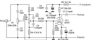
↑ Amplifier circuit
The amplifier circuit has no special features. It is difficult to come up with something in the circuitry of a single-ended tube amplifier. The output lamp is switched on by the tetrode. The output stage is covered by local OOS to reduce the output resistance. This scheme, with the light hand of Oleg Chernyshev, has long been called “Pokemon”.
↑ Output transformers
The hardware was taken from Ippon computer uninterruptible power supplies.
Size W25x45. The primary winding contains 904+1130+1130 turns of 0.18 wire. 8+10+10 layers of 113 turns per layer. A total of 3163 turns. The active resistance of the winding turned out to be about 360 Ohms. This was precisely the reason for switching on the output stage in tetrode mode. This mode is less sensitive to the high active resistance of the transformer winding. Between the primary sections there are 2 sections of the secondary winding, 94 turns each, with 0.6 wire. 2 layers of 47 turns. The secondary windings are connected in parallel. All windings are wound turn to turn, the interlayer spacer is made of check tape in one layer.
Inter-winding insulation - 2 layers of the same receipt tape. After winding, the coils are welded in paraffin to secure the turns and improve insulation. The Ra of this transformer for a 4 Ohm load is approximately 5 kOhm.
↑ Assembly and parts of the amplifier
The amplifier is mounted mounted.
There are few parts and, to be honest, I was too lazy to design a printed circuit board for it. The details are also very ordinary. Resistors R4, R9, R10 with a power of at least 1 W. The rest are 0.25 W.
Capacitors C2 C4 electrolytic at 35 Volts. Capacitors C1 and C3 are film capacitors for 400 Volts.
Lamp panels and transformers are mounted on an iron plate 0.8 mm thick. This is a cut from the side cover of the old system unit.
From wooden blocks 60 mm wide and 18 mm thick, a box with an external size of 200 × 210 mm is glued together, onto which the upper and lower iron covers are attached.
Concert power amplifiers
When holding various public events (concerts, sports competitions), multiple sound amplification is required, as well as the ability to operate for a long time at maximum power. It is precisely these conditions that concert amplifiers are adapted to, the main characteristic of which is their reliability. That is why they are protected more carefully than all previous options from overloads, overheating, and short circuits.
Let us list a few more features of this class of amplifiers:
- If household amplifiers are best used at 25-30% of the maximum power, concert amplifiers - at half of the planned capabilities, then for concert equipment 70-80% is not the limit;
- The maximum power that a concert amplifier can produce is from 2x200W (for home and studio versions this figure is from 2x50W);
- The absence of a tone block forces the customer to look for an appropriate “mixer-amplifier” pair to make the output sound even better.
Thus, if you decide to buy sound reinforcement equipment, first of all, you should decide for what purpose you need it. Well, if you need a concert version, then welcome to!
In addition, another systematization of amplifiers is possible, which is based on the level of efficiency of the device. This indicator indicates that part of the energy that is spent specifically on sound amplification (the rest is released in the form of heat). Depending on the value of this indicator, several classes of devices are distinguished:
- Class A. It corresponds to a fairly low efficiency (only 30%), but the level of distortion here is minimal. The task of devices of this class is to achieve a pleasant, seemingly warm sound;
- Class B. Here the efficiency is high (70%), but the sound quality is very low.
- Combined class AB. If the signal is maximum, then mode B is activated, but if the signal is small, then mode A. In this case, the efficiency reaches 60%.
- Class D. Such amplifiers have the highest possible efficiency (85%) and the sound quality is quite high.
Today there are a huge variety of concert amplifiers on the market, which differ from each other in various characteristics. Of course, many buyers put cost first - and this is indeed a very important parameter. In addition, if you want to buy a sound reinforcement kit, you should take into account the class mentioned above. Moreover, more and more often the choice falls on class D models.
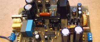
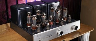
↑ Photo of the structure
A few photos of what happened as a result.
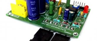
Power supply
The power supply circuit is a classic 500W (VA) toroidal transformer with dual 2x 40V secondary windings and current up to 7A. The voltage is rectified by a 35A/1000V bridge rectifier and then filtered by 6x 10000uF/63V capacitors. I soldered additional 100 nF / 100 V decoupling capacitors to the bridges. However, such a large transformer, when connected to the network, consumes a significant inrush current necessary to magnetize the core. The solution to this problem was a soft start circuit.
In a nutshell, it works in such a way that the relay contacts close approximately 2 seconds after the device is turned on. Meanwhile, current begins to flow through the limiting resistors. The delay time depends on the capacitance of capacitors C2 and C3.
↑ Results and conclusions
↑ Cons
The obvious disadvantage is the limitation of 1.8 A on the total filament current of the connected ones. The disadvantage is also the rather high price of the unit. Although, if you compare it with the cost of a TAN of similar power (to which you also need to add bridges, high-voltage electrolytic capacitors and an iron/electronic inductor), then the price no longer looks excessive.
↑ Pros
Small dimensions and light weight.
A huge advantage of this UPS is that the output is almost completely free of 50/100 Hz AC background. The Chinese switching power supply for tube amplifiers has a right to life.
You can take it! This may be meant as an alternative. It can be used to power a wide range of simple designs using lamps 6F3P, 6F5P, 6P14P+6N3P, etc. See the list above. This UPS will go very well with a headphone amplifier and a tube phono preamplifier.
I look forward to your questions and comments. Thank you for your attention!
Speaker sensitivity
This parameter determines what sound pressure (which, as is known, is measured in decibels) at a distance of 1 m can be created by an acoustic system if a power of 1 W is supplied to it. The higher this parameter, the greater the sound volume will be at the same power. Therefore, all professionals know: the volume of sound does not depend on how powerful the set of sound reinforcement equipment is, but on how well the pair of amplifier and speaker system is selected. If chosen well, at lower power the volume level can be much higher.