Hi all,
In order to avoid difficulties with calculating the mid-high-frequency filter, it may seem correct to use the so-called additional function filter (AFF) - a differential amplifier that subtracts from the broadband (musical) signal the one that was isolated by the low-pass filter (in our case) , and the remainder is the midrange and high-frequency components, which are transmitted to its output.
Practical crossover circuits with FDF are described in detail in the articles of Radio magazine:
1981 No. 5-6 page 39 “Three-way amplifier”
1987 No. 3 page 35 “Filter block of three-band AF amplifier”
Please note that in the '87/3 circuit, in front of the active filter there is a voltage follower on the op-amp, which follower has a low output impedance, and the filter on the op-amp (FDF) with a high input impedance is loaded, which is useful for matching the filter with the circuit forming the crossover, generally.
It is better to choose a crossover frequency for a two-way crossover that is three times greater than the resonant frequency of the woofer. If a full-range speaker is used as a low-frequency loudspeaker, then it is better to conduct the section above 3.5 KHz (above the resonant frequency of the selected high-frequency loudspeaker).
A table linking the crossover frequency during bi-ampling with the power that needs to be supplied to the mid-frequency - high-frequency link is given in Radio 2001 No. 9, page 10
Before this crossover, it would be good to put a high-pass filter with a cutoff frequency of 40 Hz or less - cut off what your woofer cannot physically reproduce. Audiokiller electroclub talks about this in detail. info/samodel/sub_pred. htm
An article on measuring the resonant frequency of loudspeakers and their “T-C parameters” using a computer sound card is available here on the website. /practice/loudspeakers/1366-izmerenie-parametrov-tilya-smolla-dlya-nachinayushhix. html
On the topic of two-way sound reproduction (biampling), it is interesting to read the article by V. Shorov from Radio 1994 No. 2 “Two-way sound reproduction” and, if you want to understand better, the series of articles by A. Frunze “On improving the sound quality of speakers” Radio 1992 9 - 12.
I would like to thank AudioKiller for the program for calculating third-order filters.
electroclub. info/mysoft. htm
Based on the calculations performed, I assembled a combined (on one op-amp) bandpass filter 40 – 18000 Hz for a VHF receiver. With precise selection of capacitors and resistors, the frequency response of the filter coincided with the desired one without additional adjustment.
Beginners who have successfully assembled a circuit layout can save themselves the hassle of etching printed circuit boards by using non-foil fiberglass (getinax or thick cardboard) and thin tinned wire that replaces the traces that were supposed to be etched. In the LayOut program, a printed circuit board is drawn with a track width of 0.3 - 05 mm. - to be visible. Based on the printout of the board design, protected with transparent tape, the PCB is cored and drilled. Then parts are inserted into the holes, according to the assembly order, from the entrance to the exit, their tinned leads are bent in the direction of the drawn tracks and soldered. If the leads are not long enough, use tinned wire. If the conductors - “paths” - lie close to each other and there is a risk of short circuiting, you can put on a cambric. It is important that if rework is required, for example, 20% of the assembled circuit, you do not need to cut off the printed tracks - just unsolder the section, make a new drill and reassemble - clean, simple and technologically, like paving slabs. When assembling HF structures, the foil layer facing the parts can be used as a general shield. The foil around the holes must be countersunk, except for the “ground” contacts.
If you're interested, I'll send you photos of boards made this way.
https:///amplifiers/chipamps/1802-dvuhpolosnyy-usilitel-eto-prosto. html
One of the advantages is that when a low-frequency channel is overloaded, its distortions are well masked by the mid-high frequency link, therefore the maximum undistorted power for hearing becomes noticeably greater. In the end, I managed to swing one column so much that the slate on the garage began to crack.
Scheme
The input signal is fed to the non-inverting input of the operational amplifier MC1, which serves as an active low-pass filter with a frequency response slope of 18 dB/octave, and to the non-inverting input of the operational amplifier MC2, which functions as a differential amplifier with a voltage gain Ku=1.
The inverting input MS2 is supplied with a signal from the output of the low-pass filter MS1. In the differential amplifier MC2, its low-frequency part is subtracted from the spectrum of the input signal, and only the high-frequency part of the input signal appears at the output of MC2.
Thus, you only need to provide a given cutoff frequency of the low-pass filter, which will be the crossover frequency. The values of the filter elements are found from the relations C1 = C2 = C3; R1=R4; R5=R1/6.8; R1C1=0.4/Fp, where Fp is the crossover frequency.
I took R1 22 kOhm, and then everything is calculated using formulas depending on the required crossover frequency. I tried K157UD2 and K1401UD2 as operational amplifiers, both showed good results. Of course, you can use any quad imported op-amp.
Biwiring or biamping? acoustics connection diagram
Share
In addition to the correct selection of cables, a necessary condition for obtaining maximum performance from modern high-level acoustics is the correct connection diagram. In addition to the traditional two-wire stereo connection, there is also a four-wire connection. Determining whether you need this is very simple. Just look at the terminal panel of the speaker system. If there are more than 2 poles, then it’s worth experimenting with different switching circuits! Let's consider possible options for increasing the performance of speaker systems.
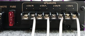
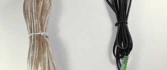
The simplest thing you can do is to replace the jumpers that come with the speakers with full-fledged cable jumpers. Ideally, from the same speaker cable that connects the speakers to the amplifier. But if the cable is factory-made or is simply not sold pre-cut, then you can simply purchase a piece of acoustic cable and make jumpers from such a piece. The jumper does not have to be of a minimum length - the cable must “open up”. However, a large length is not needed here - a segment of 15-20 cm will both look aesthetically pleasing and already “sound”. The requirement for the cross-section of jumpers is less than or equal to the cross-section of the main cable. Because The mid-HF section is connected by jumpers, then for brighter and louder high frequencies you can install a silver-plated or silver cable. Lovers of neutral sound will prefer a pure copper or even tinned conductor.
But you should remember: The effect of the jumpers is not complete precisely because of the limited length of their length.
The next stage in increasing system performance is connecting using a bi-wire connection:
In this case, we get identical wires to different sections of the acoustics and phase matching of the signal. By dividing the total cable cross-section we get better dynamics across the ranges. This happens because with a classic stereo connection, the low-frequency (most energy-intensive) part of the signal “takes” energy from the mid-high frequency range. This is especially critical when using standard wires that come as test wires included with the acoustics/amplifier - with this connection you will hear the sound from the acoustics, but you won’t be able to hear how it is truly capable of sounding. In the case of bi-wiring, each of the acoustic paths receives enough energy - the bass part does not encroach on the high-frequency part, and the mid-frequency part has enough energy to fully reveal its potential. With the correct selection of the section, of course.
Important note: A common bi-wiring mistake is trying to use 2 separate stereo cables.
At the physics level, in this case, we get a large capacitor between the amplifier and the acoustics, and aurally, we get a phase imbalance and problems with building a sound stage. The right solution is to use special speaker cables for bi-wiring with 4 cores, such as the standout in the profile edition of What Hi-Fi - Supra Rondo 4x2.5, which structurally (by laying conductors with a certain, spaced pitch and geometry of the conductors) provide minimal capacitance and Due to the use of general external insulation, they ensure the aesthetics of this solution.
And yet: But since there are still 2 terminals on the source, the effect of biwiring cannot be considered full.
A truly uncompromising connection scheme is the Bi-amplifier connection:
Biamping comes from High-End circuit technology, which, in addition to the principle of a minimal signal path, also uses the principle of sectional amplification. Those. In a high-end ideal, crossover-free separate amplification is needed for each (!) speaker. Obviously, in the case of bi-amping, we get independent gain for both the LF and MF/HF sections. To correctly coordinate the operation of the final power amplifiers, it is recommended to use a preamplifier. In case of biamping, it is not necessary to use 4-wire speaker wires, but their use can help reduce the overall number of cables behind the rack. In the case of using stereo cables, as in the case of jumpers, you can experiment with different (both in cross-section and in conductor material) cables for the low-frequency and high-frequency sections.
Cables for bi-wiring/bi-amping are presented in the section “Bi-Wire and Bi-Amp Speaker Cables”. If you have any difficulty choosing a cable for bi-wiring/bi-amping speaker connections, call us and we will advise you on the best option specifically for your case.
Source
Active crossover for biamping
| Crossover calculation program |
I slightly updated some of the pictures - as it turned out, there was a slight mix-up in the diagram and arrangement of parts - nothing terrible, but the numbering of elements in the installation did not correspond to the diagram. And the diagram itself incorrectly showed connection C4 (left terminal). Now everything is correct, and most importantly, it all matches the PCB. The printed circuit board has not changed! Everything is right there! The confusion was only on this page of the site.
Biamping is a very good thing, and the time has finally come to introduce it into my equipment (receiver). Passed all preliminary tests and samples. Well, finally a new version of the crossover . This is a further improvement of the first model. The difference is that I designed it for high-quality film capacitors such as K73-17, K73-44, K78-16, EPCOS, etc. (therefore, the board has a lot of “extra” holes for capacitors of different sizes). In addition, to reduce the dimensions of the board, I used SMD resistors of size 1206 - smaller ones won’t do much (the capacitors are still large and they determine the dimensions of the board), and soldering them is not difficult. For the same reason, I used chips in DIP packages - soldering is easy. SMD capacitors cannot be used - they are ceramic and can ruin the sound quality.
The circuit has remained virtually unchanged (this is one channel of the stereo version) - 3rd order Butterworth filters HF and LF:
The input capacitor C0 “cuts off” the constant at the input. And at the same time (together with resistor R0, which should be within 33...68 kOhm) it is a subsonic filter - it reduces the level of low frequencies, below the cutoff frequency, it can be calculated as follows:
C0 [µF] = (4…5) / Fmin [Hz]
This is for a value of 47 kOhm, if R0 has a different value, then how many times R0 is greater than 47 kOhm, the same number of times C0 should be less than according to the formula, and vice versa. It is better to choose a cutoff frequency 2...3 times lower than the lowest operating frequency you require. The exception is when you really need to cut off low frequencies, then we substitute the lower operating frequency into the formula.
Resistor R7 regulates the level of high frequencies - usually the output of the tweeter is higher, and the signal for it has to be attenuated. This is important in biamping - otherwise a frequency imbalance is possible. A multi-turn trimmer resistor is used here - it is sealed (dust does not get in and does not change the resistance), and allows you to accurately adjust the signal level. Resistors R8, R9, R10 allow you to “decouple” the unit from the power source and possible ground loops (so that the crossover can be easily integrated into existing equipment). Capacitors C7...C10 are power filters. They should be the same for “+” and “-” power.
The ratings of some parts are not indicated - they depend on the cutoff frequency of the filter. The filter itself can be calculated using this program. It is only necessary that the resistor resistances be within the range of 10 kOhm...1 MOhm (then there will be less interference and influence of the crossover on other blocks).
For myself, I made a filter with a crossover frequency of about 2.5 kHz. This is its frequency response - ideal!
I measured the frequency response the old fashioned way, using a generator (with low distortion), a frequency meter and an electronic voltmeter. The points at which measurements were taken are shown on the lines (in black and blue). The total electrical frequency response is almost an ideal straight line with unevenness no more than +-0.05 dB!!!
If possible, it is advisable to select capacitors according to their capacity, but I, for example, didn’t go too hard, they were more or less close, and that’s all. I didn’t select resistors at all, and this is what happened when viewed through a microscope:
Very good!!! The unevenness of the frequency response of the low-pass filter in the range from 20 Hz is no more than 0.3 dB! Below a frequency of 50 Hz, the input capacitor C0 affects, and above a frequency of 1000 Hz, the normal roll-off of the low-pass filter begins.
Distortion measurements showed that they (distortion) are at the level of the measurement limit - less than 0.002%. This is when using the OPA2134PA . It is not recommended to use “cooler” op-amps - you won’t hear the difference, and you’ll end up with problems with stability and RF interference. More “simple” op-amps will work quite well - the OOS depth is large and distortions are well compensated.
The board itself in stereo version turned out to be slightly larger than a matchbox. I believe that there is no point in trying to make the crossover even more miniature: high-quality capacitors are still large, and if the elements are “fitted” too closely, you will get extra parasitic capacitive couplings, and it is easier to get “snot” between the tracks.
| Download the board in SprintLayout 5.0 format, diagram and installation |
Microcircuits and capacitors are located on the top side of the board, resistors (except R7) are on the bottom.
A very important point: the board is double-sided and the holes have through metallization !!! It is almost impossible to do it under amateur conditions, and without metallization there may be no connection and no contact.
Here is the frequency response of speakers in the near field, each of which is connected to its own amplifier, and the amplifiers are connected through this crossover . Both speakers were working during the measurements, so the HF signal was present when the LF characteristics were taken and vice versa, creating some interference. But these interferences are very small. The total frequency response (calculated) is smooth and even! It can be seen that the woofer has a sharp surge at a frequency of 5...7 kHz, associated with the transition of the diffuser to the zone mode of operation. And where is it, this outlier after the 3rd order filter? (in fact, the emissions are even smaller; the signal also comes from the high-frequency speaker). Try setting up a passive filter ! And keep in mind that it will not be possible to suppress the surge with the 2nd order, much less the 1st order!
Test auditions were very successful: everyone listened! Here is a comparison of the frequency response of the same speaker (speaker in its normal place, microphone at the listening point) with a built-in passive crossover , and with biamping. This is a different column with different speakers. The waviness of the frequency response is the influence of the room (it must be said that it is quite good), and the drop below 800 Hz is the measurement peculiarities.
Of course, they can tell me that a crooked frequency response with a passive crossover (a dip in the 2...6 kHz region) is a consequence of insufficiently careful tuning of passive filters. I don't refuse! Just a couple more weeks of tweaking and it would be better! In fact, setting up a passive crossover was greatly hampered by the dependence of the resistance and inductance of the speakers on frequency (and they also depend on amplitude!). An active crossover does not sense the speaker parameters at all, so the frequency response is the best. In addition, if you remember how many coils had to be wound and unwound for a passive filter and paralleled capacitors! Horrible! And then right away, it worked! It was only necessary to select the crossover frequency and adjust the trimmer to set the level to HF.
PS. I have industrial-made boards, how to order, see here.
Phase-linear active crossover
https:///blog/741
Peter Latsky points out that in most crossovers (crossover filters for multi-way speaker systems) at the LF/HF crossover frequency there is a significant (usually 45 to 90 electrical degrees depending on the order of the filters) phase shift between the voltages at the LF and HF outputs.
This leads to significant violations of the integrity of the sound picture at medium frequencies (responsible for transmitting the voice and the main part of the spectrum of most musical instruments), since the same signal is emitted twice: by the high-frequency link and the low-frequency link with a greater or lesser time delay. The condition necessary for ideal sound transmission - the constancy of the group delay characteristic (GDT), or, what is the same, the linear phase characteristic, can in principle only be obtained by using a Bessel low-pass filter and an all-passing (phase-correcting) Delianis filter in the crossover (high-pass filter for forming the frequency response for high frequencies links cannot be used at all, since they form a phase advance, which is fundamentally incompatible, whatever it may be, with the phase delay of the low-pass filter and the Delianis phase corrector).
In a phase-linear active crossover (Fig. 1), the formation of a signal for the low-frequency section (Low output) is performed by a fourth-order Bessel low-pass filter (OA A4, A5), and on op-amp A2 a second-order Delianis phase corrector is installed, which has a linear frequency response, but the same phase response and Group delay, the same as a fourth-order Bessel low-pass filter. The differential amplifier at op-amp A3 subtracts the signal at the output of the low-pass filter from the signal at output A3 and thus generates a signal associated with the last frequency section of the high-pass filter (High output), supplied to the high-frequency section of the speaker system. In this case, the phases of the voltages at both outputs practically coincide, which ensures accurate transmission of the spatial sound picture. With the element ratings shown in the diagram, the crossover is used for an acoustic system consisting of an electrostatic high-frequency section and an isobaric (“compression”) low-frequency speaker. The LF/HF crossover frequency can be easily adjusted for other speakers by simultaneously changing the capacitance of capacitors C21, C22, C41, C42, C51 and C52.
For bi-wiring (English bi-wiring - “double wires”) of the speaker you will need 2 separate two-core cables. Both cables are connected to one pair of terminals on the amplifier, and on the speaker side, the jumpers are removed and one cable is connected to each pair of screw terminals. What does this give? In short, not much. Although it is quite possible for biwaring to have a small effect in terms of changing the resistance properties of the overall load that the amplifier defines. In reality, when using speaker cables of the correct cross-section (and therefore very low impedance), there is virtually no difference.
If you are choosing between using a single 12 AWG cable or two pairs of 12 AWG cables in a bi-wire connection, the latter option is preferable because the total resistance seen by the amplifier will be lower. However, the same can be achieved using a single 9 AWG cable.
Biamping
Biamping involves using two separate amplifier channels per speaker, one to connect to each pair of screw terminals. In this case, we get several divisions: active versus passive, horizontal versus vertical.
Active biamping
Active biamping involves the use of an active crossover that separates the electrical signal into high and low frequencies before it reaches the amplifiers, allowing each channel to reproduce only the frequency range it is assigned to. In terms of sonic differences, installing a passive crossover in active biamping speakers certainly has the potential to make a difference, but whether those changes are positive or negative depends on the quality of the implementation as well as the quality of the passive crossover. Be warned: Converting a passive speaker to an active speaker is no easy task, due to the complexities and costs associated with active crossovers, additional amplification, and cables. From a technical point of view, regardless of the possible improvements associated with active crossovers, active biamping allows the amplifier to be directly coupled to the driver, resulting in a much softer load than that provided by a typical passive speaker. This can also result in a more efficient system, given that energy is not wasted as heat in the passive components of the crossover. Intermodulation distortion in amplifiers is reduced given that each amplifier channel reproduces a small portion of the audio spectrum.
The shared load also greatly reduces the likelihood of tweeter destruction due to amplifier overload. Equally important, active bi-amping promotes more efficient power distribution, meaning it is possible to place a small amplifier for a relatively sensitive tweeter and leave a powerful 1000 W amplifier for more power-hungry woofers.
Passive biamping
Passive biamping uses passive crossovers built into the speakers, along with each amplifier channel reproducing the full range of the signal to control high and low frequencies separately. Compared to active biamping, the benefits of passive biamping are less obvious. However, separating the high and low frequencies does have some effect, as each amplifier now drives a different load than it would under normal circumstances if the entire speaker were driven individually. In general, individual networks are designed such that the "out-of-group" frequencies will have very high impedance relative to the expected bandwidth of the drivers, and will therefore require significantly less actual power from the amplifier.
There are several practical advantages to this separation. Potential output capacity is increased because little power is wasted to reproduce the aforementioned "out-of-band" frequencies. As with active biasing, the risk of tweeter failure when the amplifier is overloaded is also reduced. However, from the point of view of sound differences, they are insignificant. Differences can be made by simply using one powerful amplifier with similar or better performance than two smaller amplifiers.
Horizontal and vertical biamping
Horizontal and vertical biamping can be used for both active and passive biamping and involves the use of multi-channel amplifiers. In a horizontal arrangement, one amplifier is used to drive the treble of multiple speakers, and the other amplifier is used to drive the bass. The advantage is that you can choose amplifiers that are best suited for a particular application. For example, let's say you want to use a tube amp for the mids and highs, and a large solid-state amp for the lows. The vertical arrangement works in reverse, so that two channels from one amplifier are used to drive both the treble and bass of a single speaker. This helps to better distribute resources and protect the amplifier from overloading with low frequencies.
Note: It is important to use amplifiers with similar gain structures to ensure consistency between the bass and treble sections of the speaker system for proper integration.
Conclusion
So, is bi-amping or bi-amping better than using a single cable or single amplifier? As stated earlier, the benefits of biwarming are generally negligible if you are using low gauge speaker cable to begin with. Biamping can provide improvements in sound and dynamics depending on the hardware and implementation. However, when working with the best amplification and speaker components and crossovers, a single amplifier connecting a passive speaker can still offer incredible clarity, often comparable to competing active alternatives.
If you need any help in choosing speaker systems, purchasing or installing them, you can always contact us by phone 8-499-391-72-14, write to [email protected] or Whatsapp
BIAMPING
NOTE: This article was written several years ago, during the "third grade" of the High End craze. Now that the “ten years” are behind us , it’s funny to re-read my own texts, full of neophyte delight - “ahhh, I biamped the Sansui 607 and heard good bass!”
Ten smiley faces rolling on the floor.
I will not change anything in this article. More often than not, the biamp becomes a revelation precisely for such novice but restless audiophiles as I was , so let my neophyte delight be conveyed to you. If you are an experienced audiophile, go straight to the end of the article, where the system is described, which is today one of the pinnacles of biamping configuration.
BIAMPING
Every audiophile loses his “musical paradise” from time to time and looks for ways to get it back. Sometimes the energy spent is rewarded, and the returned paradise gives more bliss than the lost one. This article is about just such a case.
Having unsuccessfully softened the stiff suspensions of my Diatone DS-5000, I spent about two weeks trying to find a way to restore them to their correct condition. A by-product of these experiments was a wealth of experience in the use of various impregnations and a significant improvement in the sound of the audio system in the car. And yet, after long days of fiddling with acetone, nefras and other odorous liquids, I wanted more than just returning the usual sound. My soul demanded that the sound of the system radically improved, especially since I had long known that this was possible.
My SOLO KT-66 tube push-pull is beautiful, and when combined with the Audio Research SP-3 tube preamp, which is included in the Ten Best Buys in Vintage Audio list, it is doubly beautiful. But all tube amps have an Achilles' heel - bass control. It is no coincidence that some audiophiles claim that “the tube does not play Metallica.” It plays, but not as energetically as a transistor is capable of playing such music.
The fact is that the “quality factor” of the speaker – that is, its ability to return to its original state after receiving an impulse – does not primarily depend on the elasticity of the suspension. Most of all, it depends on the ability of the amplifier to resist the current flowing back. When the core moves in the coil in the opposite direction, the speaker turns into a mini-generator and sends current through the speaker wires in the direction of the amplifier. A tube amplifier can resist this current to a lesser extent than a transistor amplifier, and therefore it controls the bass less well - after all, the largest coil is installed in the bass speaker.
The bass performed by a tube amplifier can be soft, enveloping, deep, but will never be articulate. Bass guitar parts played by a tube amp are always blurred in the background. A transistor amplifier copes with such parts much better - the bass guitar is always clearly audible, and the central drum responds with noticeable pushes of air into the chest. But a transistor amplifier transmits mid and high frequencies worse – it makes them sound harsh and kills the magic of involvement.
The disadvantages of both types of amplifiers can be overcome by combining their advantages by using tube-transistor bi-amping. To do this, you need to connect the low-frequency section of the speaker to a transistor amplifier, and the mid-range and high-frequency sections to a tube amplifier. And feed the same signal to both amplifiers.
There is “full” and “incomplete” biamping. With “full” biamping, the separation of the signal from the source into low frequencies and midrange/high frequencies is performed by an additional device - an active crossover. With “incomplete” biamping, each section of the speaker receives the full signal and takes the desired band due to internal passive crossovers that cut off the excess. I don’t have an active crossover, but I have two output connections on the preamplifier and separate connections for bass and midrange/treble for the speakers. All that remains is to bring a suitable transistor amplifier for the test and you can try “incomplete” biamping.
Tube and transistor amplifiers must be of comparable power and approximately equal sound scale - otherwise the midrange will drown in the bass or vice versa. They both must be integral - that is, have their own controls to accurately set the volume levels.
After consultation with the friendly company retrozvuk.ru, the Sansui AU607i amplifier was chosen for the test. This is an inexpensive model with a rather sharp transistor sound, but as we remember, the shortcomings of transistor amplifiers appear only in the midrange and high frequencies, and I only need bass from this amplifier, which Any Sansui is great!
Technics SE-A-100 transistor terminal for the comparison test . I wanted to compare the result of bi-amping with powerful transistor sound of the highest standard, in which the notorious harshness was overcome by many technological tricks, the price of which was reflected in the weight of the amplifier - over 30 kg, and in its cost - about $ 2,500 in the mid-80s.
First, let's compare the sound of only the bass section with the tube KT-66 and the transistor Sansui. The fact that in this field the transistor outperforms the lamp is immediately audible. Sansui's bass is tight, defined, and every drum beat and bass string pluck is felt by the body. The tube KT-66 plays out all the same things toned down. If you imagine sound as an image in a camera, then we can say that when you connect the KT-66, this image loses half its sharpness.
Now let's connect both amplifiers to different speaker sections. I expect the soundstage to remain as I know it well, but the bass to be tighter. I turn on the test track, and... The sound of the system has completely changed. It's just a completely different system!
It turns out that when you connect biamping, not only the bass changes. The tube KT-66, which no longer needs to swing a forty-centimeter speaker with a six-kilogram magnet, can now direct all the forces to the mid/high frequency section, and its sound is also transformed. The sound becomes more detailed, transparent, the space between the instruments expands. It turns out that at the junction of the bass and treble there was always an unintelligible sound mess - now in this place there is a dense rhythm section. The music has more drive and clarity, but at the same time retains the magic of involvement. An excellent result that significantly exceeded expectations! To the advice to buy acoustics from the Golden Era of Audio, I can now add one more piece of advice - try to choose acoustics with the ability to separately connect the LF and MF/HF sections and eventually come to bi-amping.
Now let's try connecting the Technics SE-A-100 to the preamplifier and see who wins - tube-transistor bi-amping or transistor Titan power. More on this in a separate article .
PS I’ve been enjoying the new bi-amping sound for three days now. I noticed several interesting effects:
1. I began to immediately distinguish words spoken in tongue twisters in songs, which I had not paid attention to before. Where previously it was heard: when the world was virgin before the man has come, now you can immediately clearly hear - When the world was virgin before the man has come.
2. The demand for the quality of records has increased. The system has improved resolution and the slightest dirt on the vinyl can now clearly rustle somewhere between the instruments. Previously, this rustle was drowned in an indistinguishable mess at the junction of midrange and midbass.
3. The neighbors began to periodically knock on the heating pipe, which they had never done before in four years of my audiophile music lover. Apparently, due to improved articulation, the bass penetrates interfloor ceilings more easily and disturbs the neighbors more.
4. Led Zeppelin and Black Sabbath sound like nothing I've ever heard before. The neighbors like it too.
UPDATE : after three weeks, the “incomplete” biamping was brought to “full” with the help of two active crossovers with a cutoff frequency of 140Hz for mid/high frequencies and 500Hz for low frequencies. The sound has improved by another order of magnitude - the bass has become more collected and clear, as if the bass player had tightened his strings, and the highs and mids have become more transparent and pure.
Active crossovers are a very rare component, therefore, developing the theme of biamping, I ordered an exclusive component from a good craftsman - a preamplifier with a built-in crossover. Its advantage in a biamping system is not only that it increases the efficiency of both amplifiers, freeing them from working with frequencies that are not needed in their area of responsibility. Such a preamplifier allows you to build bi-amping for acoustics that do not have two separate terminals - for example, Technics SB 8000 or Diatone DS 3000. The acoustics require a little modification for this, but the result exceeds expectations. I think no one, with any amplification, has ever heard from these speakers the kind of output that they are capable of with two different amplifiers - tube and transistor, and an active tube crossover built into the pre.
I have collected several such systems. In this article you can learn about some of them.
__________________________________________________________________________________________
High level biamping solutions can be very interesting! the Thrax biamping system . Lyra acoustic speakers in this system are paired with Teres hybrid monoblocks or top-end Spartacus 300B tube monoblocks. The Basus active bass module operates from its own built-in 1 kW amplifier, and all bands are cross-linked by an active crossover. The system sounds phenomenal! Moreover, she works best with complex musical recordings with high compression - hard rock and symphony orchestra.
Thrax system with tube-transistor bi-amping.
You can listen to the Thrax system in our Huge Sound showroom.
If you want to order a biamping system, please contact us for a consultation.
The Huge Sound showroom is a place where music always sounds perfect.
AudioKiller's site
Bi-amping (English bi-amping - “double amplification”) - the use of two amplifiers, each amplifying the signal for its own speaker in the column. There are two types of biamping, and they do not have any special names, so I will give them my own names.
“Full” or “correct” biamping in an amplifier and speaker:
Biamping is “correct”.
Each amplifier amplifies only its own signal range - HF or LF (i.e. only part of the signal). Band separation occurs in an active crossover (filter) in the preamplifier. The speakers connect directly to the outputs of their amplifiers.
“Incomplete” or “wrong” biamping in amplifiers:
"Wrong" biamping.
Each amplifier amplifies the entire frequency range (i.e., the entire signal). This entire amplified signal is fed to the speaker, and its built-in crossover filter passes only the required frequencies to the speakers. Unnecessary frequencies are “discarded”, it turns out that they were amplified in vain.
Since such a booze has begun, there is also such a trick called “biwaring”.
Biwaring (bywaring)
Bi-wiring (English bi-wiring - “double wires”) - connecting each of the speakers of the speaker with a separate cable to the same amplifier .
Biwaring
The point of using two wires where one would be sufficient is if the cable length exceeds 50 meters, and a large cross-section wire is inconvenient. Or a crappy cable is used that is not able to transmit the entire signal to the speaker. I am not a supporter of either one or the other. (Well, you can also brag to your neighbor about how cool my equipment is. If your neighbor asks why there are two wires where one would suffice... You need to look for answers in advance in glossy audio magazines, and if your neighbor is technically savvy and these answers will not convince him - that means he’s a redneck from the deep provinces who doesn’t understand anything about audiophile)
So…
I’m setting up an active crossover, which I’m going to install in my modified receiver (see “Modification of Pioneer receivers”) and get “real” biamping in its front channels. With all its advantages, biamping has only one drawback - it requires additional power amplifiers. I have them - a 7.1 channel receiver, but I only use 5.1 of them. This means that two channels are free and can be used.
I made an active crossover for biamping a long time ago. By itself, it works great, but I don’t like the frequency response of the speakers connected to it. There is a small chance that I chose the crossover frequency poorly, but most likely it’s something wrong with the acoustic measurements themselves or I didn’t configure something else properly. What we have:
From the output of the sound card, the signal is fed to the crossover, and from it to the input of the amplifier for high-quality computer acoustics on the TDA7293 chip. A speaker speaker is connected to each of the amplifier channels. The right channel reproduces the midwoofer frequencies (below 3 kHz), and the left channel reproduces the tweeter frequencies (above 3 kHz).
In addition, in the low-frequency part of the crossover there is a 1st order subsonic (infra-low frequency filter) that attenuates signals below 40...50 Hz. This is done in order not to overload the bass/midrange speakers of the speakers - the subwoofer still works below 80 Hz.
Advantages of biamping
In addition to measuring the frequency response of the speakers using a Panasonic WM-60 microphone and a measuring microphone amplifier, I also listened to the speakers by ear. One of my speakers has a regular passive crossover inside (I now use them without any bi-amping), and the other speaker has its passive crossover located outside, and connected to the speakers via the Speakon connector. So I simply disconnect this speaker from its filter and use a direct speaker connection to experiment. The purpose of the listening was to compare the frequency response uniformity of passive and active crossovers. And then everything worked out according to science:
1. An active crossover has lower frequency response unevenness. Moreover, this is noticeable even by ear (not very much, but noticeable), despite the fact that I am not yet satisfied with the results of the tuning. Well, everything is clear here - there are no problems with matching the filters to the load, there is no variable nonlinear inductance of the speakers, there is no wire resistance. The frequency response of electronic filters turns out to be much more even - after all, their coordination with the load is perfect (for filters in speakers, their coordination with the speakers even depends on the volume level!).
2. The sound when bi-amping in the speaker is noticeably cleaner! Again, it’s not noticeable (and I listened more to the frequency imbalance), but still better. Let's take a closer look from here. Any amplifier always has two problems: a large signal amplitude, and its (signal) high frequency. With a large amplitude, the output voltage is close to its limit - the supply voltage. In this case, the bend in the amplitude characteristic is already close (see “clipping in an amplifier”) and the nonlinearity is large. This means that distortions are growing noticeably. At high frequencies it’s a different matter: usually the frequency of the first pole of amplifiers lies somewhere in the range of 10…1000 Hz (for the TDA7294 it is approximately 200 Hz), at higher frequencies the gain drops, which means the depth of feedback decreases and distortion increases again. A wideband amplifier that reproduces the entire range from 20 Hz to 20 kHz has a hard time dealing with both of these problems at the same time! Because along with low frequencies of large amplitude, the signal also contains high frequencies. And the amplitudes of all of them are summed up.
The amplifier is trying its best to maintain high quality, but how can it cope with two of them alone! And in biamping, each amplifier gets only one opponent. One amplifier struggles only with high amplitude, because with a cutoff frequency of 3 kHz and a 3rd order filter, it does not get high frequencies. And it copes with relatively low ones more easily. The other amplifier received only high frequencies, but the signal amplitude there was 10 times less. Therefore, the distortion of each amplifier becomes smaller.
In addition, in a single wideband amplifier, numerous combination frequencies appear (due to intermodulation distortion), including between the highest and lowest signal frequencies. As a result, the spectrum of Raman distortions turns out to be almost continuous, like noise, and very unpleasant to the ear. If the amplifiers are separated, then in each of the channels there is not only a smaller number of signal frequencies that create mutual combinations, but they are also “only their own” - only low frequencies or only high frequencies. The highest frequencies do not interact with the lowest ones in any way, because they are separated into different amplifiers! Therefore, there are much fewer combinations of intermodulations (and their amplitude is smaller due to increased linearity!) and the sound is cleaner.
3. In fact, there are several other factors that improve the sound. For example, the fact that the amplifier has to work with a “lighter” load. If the isolation filters are located in a column, its resistance takes on a more complex reactive nature due to the coils and capacitors that make up the filter (and there are also resonances in the filter!). And it is more difficult for the amplifier to work with such a load. “Clean” speakers are also not sugar, but still much better.
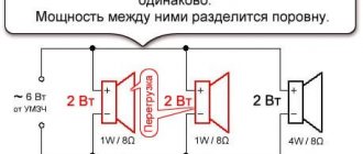
4. The output power is a little more - after all, we now use two amplifiers for the speaker. I'll explain it in my hands. Let's assume a maximum amplifier power of 10 W. This means that with “monoamping” on a speaker, this same 10 W maximum is what we get (in fact, a little less due to losses in the passive crossover). Biamping has two amplifiers, and the crossover frequency is 3 kHz. At this crossover frequency, the low-frequency/mid-frequency components account for approximately 85% of the signal power (Program for calculating the power ratio of speakers connected through filters). With “monoamping,” the amplifier power was divided as follows: 8.5 W for the low-frequency speakers and 1.5 W for the high-frequency speakers. In biamping, the low-frequency amplifier sends all its 10 W to the low-frequency speaker. Now these 10 W make up 85% of the total signal, and the remaining 15% of the signal = 2 W into the tweeter is given to another amplifier. Thus, the total power of the two amplifiers is now 12 watts! And this while reducing distortion.
Are there any disadvantages to biamping? Eat. But these disadvantages can either be turned into advantages or easily overcome. And only some of them (although also surmountable in principle) will interfere with life.
Disadvantages of biamping
1. You need twice as many amplifiers. This can be overcome easily. Of course, the scheme becomes more complicated and more expensive, but not by a factor of 2. After all, part of the price and complexity is the case, power supply, preamplifier, all kinds of indication and automation. The case becomes only slightly larger and a little more expensive. The same thing happens with the power supply. A little more powerful, a little more expensive. Not much. The preamplifier will remain almost unchanged (an active crossover in a preamplifier is cheaper than a passive crossover in speakers!). Thus, the price and complexity will increase by 20...30%. And besides, quality requires costs. For contrast, look at the catalog of Hi-End equipment with prices over one hundred thousand dollars. And it will immediately become clear to you that your amplifier is not even expensive at all!
2. It is impossible to connect headphones to the output of a biamping amplifier (as opposed to a “wideband”) (they are usually connected to the output of a power amplifier through a resistor). In fact, this is not a disadvantage, but an advantage. This headphone connection is used to make life easier. The quality is not the highest. If the amplifier is two-way, then you will have to make (and build into the device) a special headphone amplifier, which has a much higher quality! So your headphones will sound better.
3. The most painful problem: the speakers are not ready for biamping. What the industry produces is not exactly “real” biamping - although it is possible to use two amplifiers, each of them amplifies the entire frequency range as a whole. And then the filter in the column will “take” only part of the signal, and the other part will be wasted (and why would it be amplified to no avail?). Such biamping has practically no advantages over “monoamping” (in fact, it has, but much less than “real” biamping). So the problem is that the filters are already built into the speakers and there’s no getting away from them ! For full biamping, both speakers and amplifier must be designed, manufactured and sold together. At the same time, versatility is lost... But in my opinion this is not so bad. Read audio magazines and online forums! How many questions are there on the same topic: “Will the XXX amplifier sound good with the ZZZ speakers?” Or: “Which speakers should I buy for my amplifier to match?” And if these components do not fit together, then the system sounds worse than it could. And here - no problems: the speakers and amplifier initially match each other. And it is right. Indeed, in many areas of technology this is exactly what they do. After all, no one suffers: “Which engine should I put in my Ford - from Toyota, from BMW or from Zaporozhets?” So why are the pair of components that are most closely related and dependent on each other - speakers and amplifiers - still produced separately and completely independently of each other? And not always suitable?
This is mostly done for the convenience of producers, not buyers. But radio amateurs in this regard are in much more favorable conditions - they can do everything in a comprehensive manner, coordinating it in the best possible way. Or remake existing equipment, which is what I’m doing now.
15.05.2007
Total Page Visits: 3991 — Today Page Visits: 1