The editors of the “Two Schemes” website present a simple but high-quality low-frequency amplifier based on MOSFET transistors. His circuit should be well known to radio amateurs and audiophiles, since it is already about 20 years old. The circuit was developed by the famous Anthony Holton, which is why it is sometimes called VLF Holton. The sound amplification system has low harmonic distortion, not exceeding 0.1%, with a load power of about 100 watts.
This amplifier is an alternative to the popular amplifiers of the TDA series and similar pop ones, because at a slightly higher cost you can get an amplifier with clearly better characteristics.
The big advantage of the system is its simple design and output stage, consisting of 2 inexpensive MOS transistors. The amplifier can work with speakers with impedance of both 4 and 8 ohms. The only adjustment that needs to be made during startup is to set the quiescent current value of the output transistors.
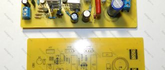
Printed circuit board
ULF printed circuit board - finished viewHere is an archive with PDF files of the printed circuit board - .
Cooling
The main part of the heat is dissipated on the housings of field-effect transistors VT10 and VT11, so they must be installed on a heat sink with a surface area of at least 1000 cm2, or at least 10 cm2 per 1 W of power.
A dielectric spacer must be installed between the transistor housings and the heat sink, and a dielectric bushing must be installed in the hole in the flange for the mounting screw (applies to the TO-220 housing).
It is very important that transistor VT7 must be installed as close as possible to VT10 and VT11, since it is responsible for thermal stabilization and does not allow the amplifier to go into thermal runaway.
It is also important to use thermally conductive paste; without it, heat transfer from the components to the radiator will be more difficult.
Amplifier operating principle
Transistors T4 (BC546) and T5 (BC546) operate in a differential amplifier configuration and are designed to be powered by a current source built on the basis of transistors T7 (BC546), T10 (BC546) and resistors R18 (22 kohm), R20 (680 Ohm) and R12 (22 rooms). The input signal is fed to two filters: a low-pass filter, built from elements R6 (470 Ohm) and C6 (1 nf) - it limits the high-frequency components of the signal and a bandpass filter, consisting of C5 (1 μF), R6 and R10 (47 Ω), limiting signal components at infra-low frequencies.
The load of the differential amplifier is resistors R2 (4.7 kΩ) and R3 (4.7 kΩ). Transistors T1 (MJE350) and T2 (MJE350) represent another gain stage, and its load is transistors T8 (MJE340), T9 (MJE340) and T6 (BD139).
Capacitors C3 (33 pf) and C4 (33 pf) counteract the excitation of the amplifier. Capacitor C8 (10 nf) connected in parallel with R13 (10 kom/1 V) improves the transient response of the ULF, which is important for rapidly rising input signals.
Useful: Diagram of a powerful 12 V 50 A power supply
Transistor T6, together with elements R9 (4.7 ohms), R15 (680 Ohms), R16 (82 Ohms) and PR1 (5 ohms), allows you to set the correct polarity of the amplifier output stages at rest. Using a potentiometer, it is necessary to set the quiescent current of the output transistors within 90-110 mA, which corresponds to a voltage drop across R8 (0.22 Ohm/5 W) and R17 (0.22 Ohm/5 W) within 20-25 mV. The total current consumption in idle mode of the amplifier should be around 130 mA.
The output elements of the amplifier are MOSFETs T3 (IRFP240) and T11 (IRFP9240). These transistors are installed as a voltage follower with a large maximum output current, so the first 2 stages must drive a sufficiently large amplitude for the output signal.
Resistors R8 and R17 were used mainly for quickly measuring the quiescent current of power amplifier transistors without interfering with the circuit. They may also be useful in case of expanding the system with another pair of power transistors, due to differences in the resistance of the open channels of the transistors.
Resistors R5 (470 Ohm) and R19 (470 Ohm) limit the charging rate of the pass transistor capacitance, and, therefore, limit the frequency range of the amplifier. Diodes D1-D2 (BZX85-C12V) protect powerful transistors. With them, the voltage at startup relative to the power supplies of the transistors should not be more than 12 V.
The amplifier board provides space for power filter capacitors C2 (4700 µF/50 V) and C13 (4700 µF/50 V).
Homemade transistor ULF on MOSFET
The control is powered through an additional RC filter built on elements R1 (100 Ω/1 V), C1 (220 μF/50 V) and R23 (100 Ω/1 V) and C12 (220 μF/50 V).
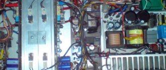
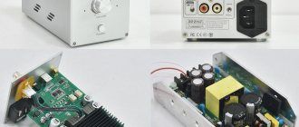
ULF class A power supply circuit
The power supply required some changes. The rectifier bridge uses BYW 29/100 diodes. 100 nF capacitors are placed around the diodes to filter out switching noise. 1 µF capacitors are placed in parallel with 10000 µF capacitors for filtering. Everything is presented in the power supply diagram.
After assembly, the amplifier worked immediately and was quite impressive. However, it should be noted that in his case, use good filtering on the power supply to eliminate hum. But otherwise, this is a fairly simple project that even a less experienced radio amateur can handle.
The transistor load is served by four non-inductive wire resistors with a power of 10 W each. Yes, Class A is very inefficient in terms of power consumption. It takes over 60 watts to get just a few watts of sound out of the speaker.
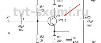
This is a typical example of an SE amplifier. The resistor acts as a current source for the transistor. The quiescent current is easily calculated as 0.8 A. The power loss is about 20 W. The theoretical maximum power is 5W.
Power supply for UMZCH
The amplifier circuit provides power that reaches a real 100 W (effective sine wave), with an input voltage of around 600 mV and a load resistance of 4 ohms.
Holton amplifier on a board with details
The recommended transformer is a 200 W toroid with a voltage of 2x24 V. After rectification and smoothing, you should get bipolar power supply to the power amplifiers in the region of +/-33 Volts. The design presented here is a monophonic amplifier module with very good parameters, built on MOSFET transistors, which can be used as a separate unit or as part of a homemade home audio complex.
Class A amplifier circuit - second option
And this is a slightly modified circuit: transistor T2 replaces the 15 Ohm 40 W resistor in the top circuit and is the current source for T3, T1 and R1 to maintain the current source current equal to Ube (0.7 V) / R1 (0.47 Ohm) = 1 .5 A. Power at R1 = Ube (0.7 V) x I (1.5 A) = 1 W. Power at T2 as well as at T3 = Uds (17.5 V) xI (1.5 A) = 26 W. Transistors T2 and T3 together remove heat with a power of 52 W. And the power on the speaker is about 12 W (at 8 ohms). The biggest advantage of a current source is that for alternating voltage it has a very high resistance.
If you need ULF class “A” purely for headphones, see this diagram. In general, try to assemble this A-class UMZCH and listen - you will be pleasantly surprised!
- ULF CLASS D WITH RADIO TUBE
- TRIODE AMPLIFIER
- SIMPLE ULF CLASS A
- PROTECTION FOR POWER AMPLIFIER
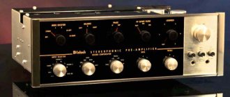
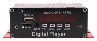
Review of sound amplifiers in standard radios
A short overview of audio amplifiers used in car radios
When choosing a standard radio for their car, buyers are interested: why, given the almost similar characteristics of various radio models, is there a significant difference in their cost? The screen is the same, GPS navigation is both there and there, Bluetooth, and much more is similar. BUT, THIS IS AT FIRST SIGHT!
This is all the preface for a long article about standard radios...
Now we will try to figure out the sound amplifiers of standard radios.
One of the elements in determining the cost of a car radio is precisely the type of Low Frequency Amplifier
in the output stage of the radio (VLF).
It is this chip that will mainly affect the sound quality. It is important to know that the sound is also affected by acoustics, wiring, an external amplifier (if there is one), sound insulation of the car, and much more - but if a cheap ULF was initially used, then it will be impossible to achieve any global improvement in sound!
The buyer often encounters this situation - the complete absence of the ULF type used in the description of the car radio. They only indicate the output power (often overestimated), less often the range of reproduced frequencies, and no more information about the sound at all. Often this information is not available on the manufacturer’s website or in the description of the radio. This is why this is done, the manufacturer puts a cheap ULF in their radios and, of course, does not talk about the model, so as not to scare off the buyer. You will certainly not remain silent about an expensive and high-quality component in your product... Therefore, if you are a lover of high-quality sound, before purchasing, be sure to ask what type of microcircuit is used in the radio. If the information is closed, although it also happens that sellers simply may not know this at all, then most likely this is a budget-friendly version of the standard head unit in terms of sound...
Sound power.
Completely depends on the chip used. And the larger this parameter, the better in the end, since the ULF reproduces without distortion only at the beginning of its Amplitude-Frequency Characteristic (AFC) - linear operating mode. That is why they like to install acoustics with a resistance of 2 Ohms in business/luxury class cars.
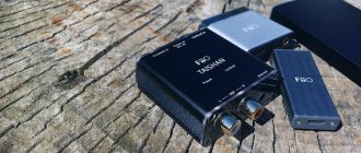
MOSFET.
When describing an amplifier, you can often see this inscription on radio tape recorders.
If the manufacturer is not deceiving, then his product uses a ULF microcircuit, which is made using MOSFET technology:
this is a technology for producing composite (bipolar + field) on one substrate, where at the input there is a bipolar with a low-impedance input and swings a high-resistance field input, which has its own turn very low resistance of the open junction.
As a result, consistency in input and output, as well as less power dissipation. That is, the level of parasitic noise is lower. This technology is used in high-quality amplifiers. MOSFET
- are called field-effect transistors, the characteristics of which are very well suited for use in amplifiers, since they do not have RF interference! They are considered to have the best signal-to-noise ratio. In short, MOSFET is good!
Below we present the main types of ULF chips used by manufacturers in radio tape recorders. This brief description will help you make the right choice based on your audio quality needs.
We would like to emphasize that the criteria for assessing sound are individual for everyone!
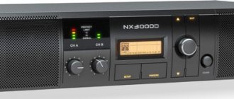
Amplifier TDA 7388
This is a budget microcircuit without outstanding characteristics and is installed everywhere in all cheap radios.
Characteristics:
- 4 channels x 41W MAX at 4 Ohm load
- THD 4 x 25W 4Ohm (14.4V, 1KHz) -10%.
This amplifier cannot be used in conjunction with premium acoustics with an input impedance of 2 ohms. The amplifier reproduces sound quite mediocre. The sound picture clearly shows the absence of clear highs and no “softness of the lows.” If you have even a little “sound hearing”, you will not like this ULF model.
Amplifier TDA 7850 MOSFET
Characteristics:
- power 4 channels x 50W/4Ohm MAX. (4x30W/4Ohm 14.4V, 1KHz, 10%)
- power 4 channels x 80W/2Ohm MAX. (4x55W/2Ohm 14.4V, 1KHz, 10%)
- manufactured using MOSFET technology
The amplifier matches perfectly with 2 Ohm speakers. It has a low level of parasitic noise and a high signal-to-noise ratio, which corresponds to the HI-FI class. Gives a rich sound picture. Great sound. Installed in devices such as RedPower
, some models
Carmedia
,
DayStar
and others.
Amplifier TDA 7560 MOSFET
A cheaper analogue of the ULF TDA7850 model.
It has similar basic characteristics, but is much cheaper in cost. Developed specifically for use in a car. Characteristics:
- power 4 channels x 50W/4Ohm MAX. (4x30W/4Ohm 14.4V, 1KHz, 10%)
- power 4 channels x 80W/2Ohm MAX. (4x55W/2Ohm 14.4V, 1KHz, 10%)
Compatible with 2ohm acoustics. It reproduces quite decently, but there is no feeling of “sound transparency”. In general, it has proven itself on the positive side.
Amplifier TDA 7851A MOSFET
A further development of the TDA 7850 amplifier, but adapted specifically for use in car radios. It has identical characteristics to the ULF 7850, but the output power is slightly reduced, due to this the manufacturer has achieved less heat generation in the limited volume of the radio.
Characteristics:
- power 4 channels x 48W/4Ohm MAX. (4x28W/4Ohm 14.4V, 1KHz, 10%)
- power 4 channels x 72W/2Ohm MAX.
- manufactured using MOSFET technology
The amplifier matches perfectly with 2 Ohm speakers. It also has the highest class AV sound, with a low level of sound distortion and minimized losses. Various types of protection are built-in, including thermal ones; displacement currents between channels are monitored and adapted to changes in the supply voltage. Excellent sound transmission, clear fronts in the low sound segment, no “sound blurring effect” or “frequency sticking together” - all harmonics are clearly pronounced. As with the 7850, the sound is excellent.
Bottom line
To summarize, several important points can be highlighted:
- First, and most important, as we wrote above, the criteria for evaluating sound are very, very individual! Therefore, as recommended.
- The best sound in TDA 7850 / TDA 7851A amplifiers.
- TDA 7560 is also a good option.
- TDA 7388 is suitable for you if the sound quality in the radio is not so important.