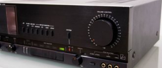
Car amplifiers take the signal from the head unit, amplify it, and transmit it to the speakers. This allows you to get more powerful and clearer sound from the speakers than if the signal were supplied directly from the signal source to the speakers. Ideally, if the amplifier transmits the signal linearly - the output signal has the same shape as the input, only with a larger amplitude, which determines the sound power. This transmission of the signal form is called frequency response - amplitude-frequency characteristic, which shows how the amplifier transmits a signal at different frequencies. The smoother the frequency response, the better for signal quality.
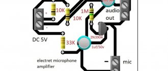
Parsing the circuit
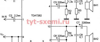
This is a mono audio power amplifier.
Transistor VT1 is the main element in the amplifier circuit. Therefore, the circuit is called a transistor ULF (low frequency amplifier).
In this case, an NPN transistor is used. It is connected according to a common emitter (CE) circuit. This circuit allows you to get the most out of the transistor. It amplifies both voltage and current at the same time. Total maximum power.
How exactly is the switching scheme determined? The incoming signal is fed to the base and emitter, and the output signal is taken from the collector and emitter. That is, in fact, a common emitter contact. That's why the circuit is called common emitter. The emitter is the power part of the transistor, which allows you to amplify the signal to the maximum.
This circuit has one amplification stage.
What is a cascade
A cascade is essentially an amplification stage that is independent of the other. There are also two-stage amplifiers. That is, for example, there are two transistors in the circuit. One works as a preamplifier and transmits the amplified signal to the input of the second. Therefore, the circuit is called two-stage. They are independent of each other, but the first stage transmits the signal to the second, which allows the signal power to be increased.
Anatomy of the device
Audio amplifiers can be thought of as a simple box or block containing a device such as a bipolar, field-effect transistor, or operational sensor that has two input and two output terminals (ground being common). Moreover, the output signal is much larger due to its conversion on the device.
An ideal signal amplifier will have three main properties:
- Input impedance, or (R IN).
- Output impedance, or (R OUT).
- Gain, or (A).
No matter how complex an amplifier circuit is, a general block model can be used to demonstrate the relationship of these three properties.
How to eat scheme
The quality of the amplification also depends on the quality of the power supply. No matter how outstanding the characteristics of the transistor, if the power supply is poorly filtered or insufficient, then the amplification will be of advisable quality.
6 V power is connected to terminals X3 and X4.
This circuit can also be powered by a battery. However, despite the fact that the battery is a source with minimal noise, the battery also has its own resistance.
And so that it does not interfere or affect the operation of the amplifier, a smoothing and storage capacitor is needed.
Electrolytic capacitor C3 stores energy from the power supply, which improves the quality of amplification. The higher the capacity, the better. Naturally, this rule has limitations. If you install too large a container, there will be a large load on the power supply.
In addition, electrolytic capacitors must discharge after switching off. Moreover, there is a limit to increasing the capacity for the circuit. If a capacitor with a capacity of 1 farad (1,000,000 μF) is connected to this circuit, then the noise level at the amplifier output will be the same as at 1000 μF. This is due to the fact that the transistor also has its own “noise”, lack of shielding at the input, dynamic distortion and other parameters.
During circuit design, all these parameters are calculated. Here in the circuit, capacitor C3 has a capacity of 47 microfarads - this is enough for our transistor, since it does not have much power that it can produce. You can also supply a larger capacity, for example, 1000 microfarads. The main thing is not to carefully install a capacitor with a lower voltage limit. If you put a capacitor less than 6 V (power supply to the circuit), the capacitor will start to heat up and may even explode.
General concepts
High-quality audio amplifiers may differ in their characteristics. Each type has digital or analog conversion. To separate them, codes are established.
The increased difference between the input and output signals is called conversion. Gain is a measure of how much an amplifier "converts" the input signal. For example, if there is an input level of 1 volt and an output level of 50 volts, then the conversion will be 50. In other words, the input signal has been developed by 50 times. An audio amplifier performs just this task.
The conversion calculation is simply the ratio of the output divided by the input. This system has no units as its ratio, but in electronics the symbol A is commonly used for amplification. The conversion is then simply calculated as "output divided by input".
Amplifier input
The amplifier input is terminals X1 and X2.
X2 is the minus of the input, and X1 is the plus. Since the circuit is for one channel, the ULF is called mono.
You can connect both the left and right channels, or both at once.
Input filtering
Electrolytic capacitor C1 allows you to separate the DC component of the incoming signal from the variable one.
Simply put, it only passes the AC signal. If there is no signal, or the amplifier input is short-circuited, then without this capacitor the transistor may go into saturation mode (maximum gain), and an unpleasant wheeze will appear at the output.
Do not confuse this effect with whistling. The whistle is the influence of positive feedback, and in this case there will be a saturation mode due to a short circuit at the input. And at the output of the amplifier, it is the wheezing that will be heard, and not the sound or sound.
The capacitance of the capacitor is matched to the frequency of the sound signal. The sound starts from 20 Hz and up to 16 kHz.
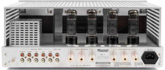
LAMP!
Gain classes are a completely logical and understandable way to distinguish one typical circuit from another. However, when applied to tube circuitry, this approach turned out to be insufficient.
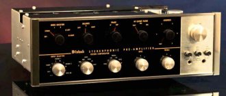
How tube amplifiers work, or Features of a warm sound Article
Amplifiers Theory and practice Cayin how an amplifier works
naumov September 06, 2022 at 09:10
20 5
The selection was prepared with the support of , the amplifiers were tested in the listening rooms of the salon
Operating point and base offset
To ensure that the transistor does not distort the input signal, you first need to open it slightly.
This can be done using a voltage divider consisting of two resistors R1 and R2. This voltage divider allows you to slightly open the transistor VT1 so that the input signal does not waste its electrical energy on its opening.
The current that flows through R1 and R2 goes to the base of transistor VT1, which then goes through the emitter, thereby opening it. This is called the base bias of the transistor, that is, its opening. The bias voltage determines the operating point. In this case, a class A amplifier.
How is the amplifier class determined?
The class of an amplifier is determined by its operating point. The operating point is selected using the current-voltage characteristic of the transistor. The higher the voltage applied to the transistor input, the greater the current, the higher the operating point.
For example, the point in the center is class A.
And the class is the highest quality of amplifiers. It amplifies both the positive and negative half-waves of the input signal. At the same time, this class has a significant drawback. This limits power and reduces energy efficiency. The fact is that as long as no input signal is received at the ULF input, it works all the time while it is turned on.
It turns out that this wastes excess electricity. Therefore, the operating point is also called the resting point, when the amplifier does not amplify the input signal.
The sensitivity of the amplifier also depends on the operating point.
There are also class B, AB and D. They differ from each other in amplification efficiency and the presence of distortion. It all depends on the scheme used.
For example. Class D does not open the transistor at all, but from the point of view of energy efficiency it is the best choice. The transistor does not consume anything at rest; it turns on only when an input signal is applied. And at the same time, if an analog audio signal is supplied to the input, it is distorted. Such a class will not be suitable for the scheme that we are analyzing in this article.
Therefore, circuit designers and engineers invented digital amplifiers. Their analog signal is converted to digital, and only then fed to the input of the amplifier. The transistor does not distort the signal with the input digit. After amplification, the signal is again converted to analog with the least loss and distortion.
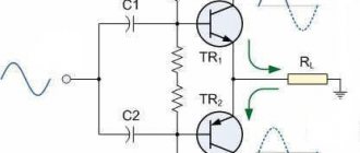
And the AB mode is used in circuits where there are several transistors that operate at their own half-waves. There are circuits where one transistor amplifies only positive half-waves, and the second only negative ones. Such amplifiers are called push-pull.
Using one converter
If implemented correctly, any of the above blocks beyond Class B can form the basis of a high precision amplifier. Aside from potential performance pitfalls (which are primarily a consequence of design decisions rather than inherent to the class), the choice of block type is largely a matter of cost versus efficiency.
In today's market, the simple Class A/B audio amplifier dominates the market, and for good reason. It works very well, is relatively cheap, and its efficiency is quite adequate for low power applications (>200W). Of course, as drive manufacturers try to push the boundaries of supply with, say, the 1000-watt Emotiva XPR-1 monoblock, they are turning to Class G/H and D designs to avoid double-duty use of their amplifiers as systems that can quickly heat up the equipment. Meanwhile, on the other side of the market, there are Class A fans who may forgive the unit's lack of efficiency in hopes of cleaner sound.
Stabilization of the circuit operation
When a semiconductor heats up, its resistance decreases. The transistor is made of a semiconductor, and accordingly its pn junctions are too.
When the ULF circuit operates, current flows through the transistor and it heats up. Typically all power is dissipated at the collector. Nevertheless, the characteristics of the transistor change dramatically, since the resistance of its pn junction decreases sharply as the temperature rises.
To stabilize the operation of the transistor, you need to balance its resistance with another source. This can be done using additional resistance.
When the resistance of transistor VT1 decreases, resistor R3 takes part of the voltage onto itself and does not allow the current in the circuit to increase.
Thanks to this, the transistor:
- does not close;
- does not go into saturation mode;
- does not distort the signal;
- and doesn't overheat.
This is called thermal stabilization of the amplifier.
And so that in normal operation, when VT1 does not heat up, resistor R3 does not reduce the power of the circuit, a shunt electrolytic capacitor C2 is included in the circuit. The variable component of the input signal passes through it without loss.
Amplifier output
At the output of the amplifier, you can connect either another amplifier, which will amplify the signal even more, or a dynamic head. The dynamic head is a regular speaker. It will reproduce the sound from the output of transistor VT1.
However, there are many nuances here too.
The most important thing concerns the matching of the load resistance and the amplifier resistance.
If the output resistance of the transistor is much greater than that of the dynamic head, then it will not be able to transmit all the power. At a minimum, most of the voltage will remain on its contacts.
This circuit requires a speaker with a resistance of about 1 kOhm.
If you set it less, for example, by 4 Ohms, then even half the power will not be reproduced, and the VT1 collector will begin to heat up even more.
The matching of the input, output and amplifier load resistances is calculated at the circuit design stage. Therefore, they should not be violated.
Bottom line
After all, converter classes aren't necessarily that important. Of course, there are actual differences, especially when it comes to cost, amplifier efficiency and therefore weight. Of course, a Class A appliance with a power of 500 W is a bad idea, unless, of course, the user has a powerful cooling system. On the other hand, differences between classes do not determine sound quality. In the end, it comes down to designing and implementing your own projects. It is important to understand that transducers are only one device that is part of an audio system.
How does current flow through the circuit?
At the initial moment of time, when the power is connected, the electrolytic capacitor C3 is charged, and the collector and emitter of the transistor VT1 begin to be powered. And also the current passes through the voltage divider.
The voltage divider R1, R2 biases the base of VT1. The base-emitter bias current (B-E) begins to flow, thereby establishing the ULF operating point.
When the input signal arrives at terminal X1, it passes through C1 and through the divider enters the base of VT1 and partially leaves through the emitter.
The input signal is attracted by the collector VT1 and thereby amplified.
That part of the alternating signal that has passed to the emitter of the transistor is amplified by the emitter current. It passes freely through C2, which, paired with R3, stabilizes the amplifier’s operating mode from overheating and distortion. As a result, the input signal, amplified by the collector-emitter (C-E) current VT1, is sent to the output, that is, to the dynamic head BF1.
What determines the power of the circuit?
This scheme has limitations. You can change VT1 KT315 to a more powerful one, which will have a higher gain, but this gain limit is not infinite.
First of all, it all depends on the transistor used. If you change it to a more powerful one, then the gain will be higher. But it should be remembered that the more powerful the transistor, the more powerful the input signal is needed. In addition, you will have to recalculate all components. And connect the preamplifier, assemble the power supply circuit, and this will be a completely different circuit.
Transistors have a number of parameters that affect the circuit. This is the gain for current (h21e), voltage, power. Another important parameter is the power dissipation on the collector. As power increases, a radiator will be required to remove heat.
Operating principle
An audio amplifier works on the principle of converting the DC power drawn from the power source into an AC voltage signal applied to the load. Although the conversion is high, the efficiency from the DC power supply to the AC voltage output is usually low.
An ideal block would give the device an efficiency of 100%, or at least the IN power would be equal to the OUT power.
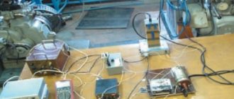
How to assemble a circuit
The circuit can be assembled on a PCB or on a breadboard. Follow the link to this article, it describes in more detail the process of assembling and testing the circuit.
Use quality parts and good solder. She's working. This is generally a classic circuit for connecting a bipolar transistor with a common emitter.
Also on the site there are other amplifier circuits that are not difficult to assemble and not expensive in terms of the cost of parts.