Homemade amplifier on a finished LM1875 board + audio input selector
So, I wanted to build a home amplifier for listening to music and watching movies. And I must say, I succeeded, and I am very pleased with the result. I’ll say right away that the “go to store” link leads to the store, not to the product. Because The amplifier is currently out of stock but can be found elsewhere.
As a basis, on the advice of my friend, I chose an amplifier based on the LM1875 chip. The amplifier board contains the four aforementioned chips: one for each channel, and the pair operate in bridged mode for the subwoofer.
LM1875 deserves all praise; in terms of its performance, it significantly surpasses many ICs of the same class produced by other manufacturers. This is true; today, the manufacturer (National Semiconductor) is one of the clear leaders in this field, owning unique technology. But most importantly, NS microcircuits are famous for their high reliability. Arguments for LM 1875: 1 - much more reliable than TDA2030 2 - better characteristics than TDA2030 Arguments against TDA2030: 1 - these ICs have a bad habit of “burning”, although this is putting it mildly - I myself witnessed how they EXPLODE , scattering fragments of the hull around. 2 - in terms of such an important indicator as nonlinear distortion coefficient, the TDA2030 lags behind the LM1875. 3 - obvious fakes from "leftist" companies often go on sale (the body shape of the fakes is strictly rectangular) 4 - even among branded products, outright defects are often found
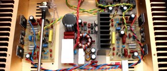
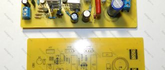
The manufacturer promises 25W per channel and 50W per subwoofer. As a bonus, the board has a tone block based on a pair of NE5532 operational amplifiers, which is characterized by good sound performance. Here is the amplifier board:
The board is marked TDA2030, because...
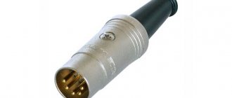
These chips are, I assume, theoretically interchangeable. Next is the input selector. Because I wanted to use the amplifier with different sound sources, then such an element makes switching very easy - there is no need to juggle the connectors, just switch to the desired input with a flip switch. However, to avoid interference, the audio signal is switched through a relay. I couldn’t immediately find a photo of exactly the same option as mine. Here is a photo of a similar one:
I had it already assembled and with RCA sockets
Now the body. For the case, I used a VCR with a minimalist front panel design. I found and bought some Goldstar for literally hundreds of rubles.
It should be noted that this photo shows an already assembled amplifier with volume control knobs and input selector controls. The video looked the same, only there were buttons instead of handles.
All the stuff from the VCR went to the trash (what am I writing!? To what trash? In the box and in the garage. After all, there are so many goodies like cogs, gears, etc. :)), some partitions in the case were cut out:
The filter and power connector are already installed here.
And now a small digression about what happened with my order. When I was looking for an amplifier board, I wanted it to be blue - this is such a design whim of mine. Not red, but blue! I found it in one store, but there you had to buy several of them in one lot. I asked the seller if it was possible to send one - yes, you can! But a little more expensive. Then I asked for luck if they had a selector board (they didn’t have one in the store), the seller asked for a photo of what I needed and said, no problem, we’ll find it! Then he sent me an invoice with pictures and prices, I paid and waited. A month later I received the treasured parcel and unpacked it. Damn it! The fee is RED! And capacitors of smaller capacity, and in general, not the same coat!
I wrote to the seller without hoping for a favorable outcome... But the seller’s reaction, to be honest, pleased me! He, or rather, as it turned out later, SHE, asked for a photo of what I received. Then they decided something with their boss and the sweet girl Shirly apologized many times for the mistake and said that I would soon receive a new amplifier board. Not having time to recover from such pleasant news, I receive a notification from the post office. What's happened? And this new amplifier board has already arrived! In 9 (nine) days! Moreover, the package is heavy, weighing 0.5 kg. Having opened it, I found the treasured board there, and even with a massive radiator, which was carefully screwed to the microcircuits! Such a surprise! My gratitude knew no bounds. I think that the integrity of the people working in this Mitao e-mart
deserves respect!
This respectable team wishes me a Happy New Year:
In general, this store deals mainly with accessories for action cameras such as GoPro, but there are also a number of other products.
This was a commercial break, now let's continue. It's time to think about nutrition. Powering an amplifier is like the foundation for a house. I have read many times how they connect amplifiers to a switching computer power supply, and then complain about distortion. There are no miracles; transformers are needed for normal sound. But in my case, two of them were needed, because... The power supply for this amplifier is bipolar. Excellent transformers were discovered in old uninterruptible power supply systems. By measuring the resistance of the outputs, we find where to connect 220 volts, and where to get the alternating voltage to power the amplifier.
About 14 volts alternating under a light load - just what the doctor ordered!
So, we throw all the parts into a pile, connect them using temporary wiring, everything works, and how, the sound is pleasant, there is no distortion.
Let me note that this design does not pretend to be any kind of oxygen-free hi-fi, but it is quite suitable for sounding a small room of 20 m2. For now, I use Attitude Alfa 20 bookshelf speakers as speakers. And then I used the subwoofer output to a simple BBK 30W sub, I set the low-frequency power control to about 15% of the maximum, otherwise the speaker starts to tear.
I placed all the components in the case:
This is the input selector:
The treasured BLUE amplifier board with a massive heatsink:
Back view:
The plans are to turn it on and off with one tactile button and install a delay module for turning on the acoustics, because... There is a clicking sound when turning the power on and off.
In conclusion, a video about why this was all started and how we “torture” the sub . Today is Children's Day, so my daughters play the main role in the video. The recording, unfortunately, does not convey the entire sound atmosphere.
How to connect to the standard radio
To connect the amplifier to the car radio, you need to remove the head unit, gaining access to the outputs on the rear of the case. Signal cables are laid along the shortest route; installation will require lifting the carpet and dismantling some of the plastic coverings. Interconnect cables are laid at a distance from the standard electrical wiring of the vehicle.
The cords brought out into the instrument panel are connected to the connectors; an additional control signal cable is laid, which is switched to the Rem output (used for synchronous start-up and shutdown of the amplifier).
If the radio is equipped with a standard microphone or additional USB outputs with extension cables, you should check the tightness of the connectors and install the head unit in the standard socket. Then you need to install the removed plastic frames and air deflectors.
Connecting two-channel and four-channel
Connecting the amplifier to the standard radio depends little on the number of channels. The power cable is routed into the engine compartment through the holes in the engine panel. On some cars, the battery is located in a niche under the rear seat or in the luggage compartment. The cord is laid parallel to the standard wiring under the floor carpet; it is not recommended to bend the insulation over the sharp edges of the body panels. The negative cable is led out to the ground bolt or out to the car battery.
Then interconnect cables and a synchronous switching cord are connected to the amplifier; details of connecting the equipment are given in the factory operating instructions. The speakers are connected to the channel terminals; negative cords are prohibited from being combined into a common circuit or connected to the car body. When switching loudspeakers, you should take into account the location of the loudspeakers and the purpose of the channels. If the connection is incorrect, the sound picture is disrupted.
The subwoofer connection diagram includes the output of signal cables to the rear channels via a bridge circuit. The positive signal is taken from one rear output, and the negative signal from the opposite one. The remaining front outputs are used to power standard speakers connected side by side into common circuits. The type of connection depends on the resistance of the coils; the total value must correspond to the technical characteristics of the amplifier.
Connecting a single channel
1-channel type devices are used to power a passive car subwoofer. Due to the reduction in the number of channels, the power of the device increases, which allows it to operate with a load of up to 4 ohms. The design of the equipment uses a special electronic filter that limits the frequency of the audio range to be amplified. The bass amplifier for the subwoofer is a product type D.
The equipment is connected to the subwoofer using 2 cables connecting the positive and negative outputs to the speaker coil. Connecting the amplifier to the radio is carried out according to the method outlined above. It is allowed to use 2 identical subwoofers, which are connected into a single circuit using a parallel or series circuit. Negative outputs are switched to the amplifier block. Do not connect cables to vehicle body parts.
Connection without tulips
If there are no linear outputs on the head unit (typical of Chinese car radios), the cables from the speakers are connected to standard acoustic outputs through additional resistance. For switching, you will need to purchase 2 resistors with a nominal value of 0.1 and 1.0 kOhm. The elements are soldered into circuits, ensuring that the signal amplitude is reduced to an acceptable value.
It is possible to connect the amplifier through a ready-made adapter, which is connected by cables to the outputs on the head unit. On the other side of the block there are cords with tulip-type connectors, which are connected to an amplification device. It is recommended to check the operation of the paired devices in different sound modes, since the converter reduces the quality of the transmitted signal.
Connecting Chinese repeaters
Many users buy Chinese amplifiers to save money. This raises the question of how to configure a WiFi repeater from China so that it works correctly. Let's look at the connection principle using a standard amplifier as an example.
To connect, follow these steps:
- Plug the product into the outlet and wait until the operation indicator lights up. Try to keep the device as close to the PC as possible.
- Wait until the indicator lights up if the device is connected via WiFi. Otherwise, connect to it using a wire.
- When setting up a WiFi repeater from China, the latter must be within the coverage area of your wireless home network. Click the icon and select Connect.
- As soon as the information about the new router appears, click on the link to connect to the network.
After this, the Internet will turn off, and a sign will appear in the PC tray indicating that the amplifier has been successfully connected.
Now you can set up a Chinese WiFi repeater. To do this, follow these steps:
- Log in to your browser and enter the IP of the amplifier in the address bar, which is indicated on the device itself or in the instructions. As a rule, you need to specify 192.168.10.1.
- Enter your authorization details to log into the control panel. Most often you will need to specify admin twice.
- In the menu that appears, configure the connection mode in the Wireless repeater mode column. Select Repeater Mode or AP Mode for WiFi or wired connection respectively.
- Find your network from several proposed options, then click on it and confirm your choice using the Apply button. If prompted, enter the password.
- If the required network is not available, click the update button.
If the setup of the Chinese WiFi repeater was successful, a corresponding connection message appears. The interface is no longer needed and can be closed. At the same time, the signal level increases.
The instructions discussed above concern the situation when a WiFi repeater needs to be configured from scratch. The situation becomes more complicated if settings have already been made to the repeater and you cannot get into the interface. In this case, you need to configure your PC. For this:
- Turn on the amplifier and connect it to the PC using a cable.
- Log in to the Network and Sharing Center and go to the section for changing adapter settings.
- Left-click the local network icon and go to the properties section.
- In the new window, select TCP/IPv4 and its settings.
- Click on the “Use the following IP” checkbox and enter the following data - 192.168.1.111, 255.255.255.0, and 192.168.10.1 for the IP, mask and gateway, respectively.
After saving the settings, you can log into the WiFi repeater and use the network as usual.
Common problems and their solutions
Many users know how to connect a WiFi repeater, but still face difficulties in getting the job done. There can be many reasons, starting from incorrect switching on, ending with the inability to configure the work. For example, the repeater for some reason does not see the router. It happens that there is a connection, but there is no access to the Internet. In this case, follow these tips:
- Place the router as close to the repeater as possible. In most cases, it is not possible to set up a WiFi repeater due to a weak signal or the repeater being outside the network coverage area.
- If you cannot connect the repeater using the button, use the setup method through the control panel. Above are instructions on how to do this correctly.
- If you have problems connecting the repeater to the router or there is no Internet, return to the factory settings. After this, restart the router and try setting up the connection from scratch.
- Please note that the repeater software can be updated. If possible, install new firmware and then try connecting again.
- Log into the router and change the network channel. Perhaps the incumbent is very busy.
Using these recommendations is enough to set up a repeater yourself to enhance WiFi, and subsequently eliminate connection difficulties. If you have questions, you can dial your provider's number or create a topic on special forums to get help from specialists.