Good and loud music in the car - this is what many car enthusiasts want, especially young people. But there is a problem: not every car is already equipped with a high-quality audio system. Therefore, in this article we will try to fully and clearly explain how you can independently connect a subwoofer to a standard radio, to the one you already have, installed by the manufacturer.
I really want to make a reservation right away. What if you decide to do all the work yourself and connect an active subwoofer, then the responsibility will be yours personally. But there is no need to experience unnecessary fears, if your hands can hold a screwdriver and pliers, then connecting the amplifier to the standard radio will be within your power.
Car subwoofer: types and design features
A subwoofer (SBV) is an acoustic system that converts low-frequency sound waves.
You don't need it to listen to most music tracks. A sub is needed for high-quality sound of low frequencies (bass).
Subwoofers come in two types:
- Active - they already have a built-in power amplifier;
- Passive - there is no amplifier and requires additional connection so that the output sound is clear without distortion or interference.
A passive subwoofer may look like a regular large speaker or a box in which the speaker is placed.
Structurally, an active sub consists of the following elements:
- body - wooden or plastic;
- woofer;
- signal regulator;
- amplifier;
- signal frequency regulator.
This is interesting: How to connect your phone to the radio in your car in all ways
For high-quality sound, the active sub must be correctly connected to the radio.
Types of subwoofers by design:
- Horn - the type has a folded horn-speaker, used at concerts;
- Closed - is a speaker installed inside and tightly adjacent to the walls of a closed box;
- Bass inverter - a type using a ventilation pipe, from which, under the force of sound waves, air comes out along with low-frequency sound;
- Quarter-wave resonator - acoustics with a tunnel design, a tunnel-pipe, of a given length and cross-sectional size through which sound comes out;
- Bendpass is a box with a bass inverter, divided in the middle by a wall into two chambers, different in volume, the speaker is placed in the partition between them.
Connecting a subwoofer to a radio via an amplifier
To connect the SBV to the car radio you will need a set of tools and materials:
- knife;
- set of screwdrivers and keys;
- pliers and wire cutters;
- insulating tape;
- circuit breakers;
- capacitor;
- consumable fasteners (nuts/bolts);
- O-rings;
- wiring (“tulips”, speaker cable, power supply).
Important: before connecting, be sure to disconnect the terminals from the battery to avoid short circuits.
Connection process
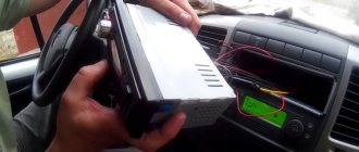
Select a location in the car to mount the device. Depending on the model and size, this will be the trunk or the cavity under the rear seat of the car.
Now you need to lay the power cable from the battery from under the hood to the place where the amplifier and subwoofer will be installed in the luggage compartment. The connecting wires from the radio to the amplifier are laid in the same way.
Next, connect the “black” and “red” wires to the “-” and “+” contacts of the amplifier, respectively.
When the amplifier is powered, it is connected to the car radio; ordinary RCA wires - “tulips” and a power wire (usually “blue”) are suitable for these purposes.
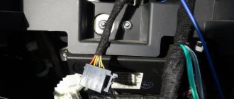
Now you need to carefully remove the radio using a screwdriver and knife.
Then “tulips” are connected to the radio according to the colors of the connecting wires. In order for the sub to turn on simultaneously with the car radio, you can immediately connect the “+” power wire.
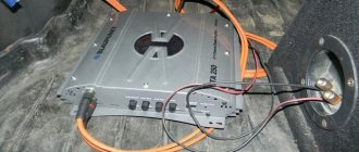
RCA connecting wires are connected to the amplifier ports according to polarity. The power cable is also connected.
An additional fuse is inserted into the resulting connection diagram to protect against voltage surges and short circuits. It is better if it is installed next to the battery so that it can be easily changed.
Next, the wires are connected to the radio into the linear output connectors (LO), and their opposite end into the LINE-IN connector of the amplifier.
Recommendation: To avoid voltage surges in the car’s electrical network, experts advise additionally installing a capacitor on the circuit. This is not necessary if the subwoofer power is below 350 W.
Advice: in order for the sound to be of high quality and reproduced without interference in the connections, it is recommended to use speaker wires with a cross-sectional thickness of 4 mm or more.
Pinouts for various brands of cars and radios
The wiring of the linear outputs on the standard radio depends on the make of the car and the head unit.
Before pinouting the connectors of the car radio, you must read the information presented on the cover of the device and in the instructions for it.
Toyota
For a standard plug: 1 - A+, 2 - GND, 3 - BAT+, 4 - backlight, 5 - antenna adjustment, 9-16 - speakers (RR+, RR-, RF+, RF-, LF+, LF-, LR+, LR -).
Universal connector for most models: 1 - ANT, 3 - linear output LR, 4 - GND linear outputs, 5 - linear output RR, 6 - CD in LCH, 7 - CD in GND, 8 - CD in RCH, 9 - CD reset , 10 — CD clock out, 11 — CD DSPL select, 12 — CD data out, 13 — CD clock in, 14 — CD data in, 16 — A+, 17 — GND, 18 — ANT GND, 22-27 and 29- 30 — speakers (LF-, LR+, RF-, RR+, LF+, LR-, RF+, RR-), 28 — CD mute, 31 — ANT CONT, 32 — CD ACC CONT, 33 — AMP CONT, 34 — B UP .
Nissan
Standard circuit: 1-6 - speakers (LR+, RR+, LR-, RR-, LF+, RF+), 7 - A+, 8 - backlight, 9 - BAT+, 10 - LF- speaker, 11 - RF- speaker, 12 - antenna control, 13 - GND.
Honda
Standard connector: 1 - RR+ speaker, 2 - LR+ speaker, 3 - backlight, 4 - BAT+, 5 - A+, 6 - antenna control, 7-10 - speakers (LF+, RF+, RR-, LR-), 13 - GND , 14-15 - speakers (LF-, RF-).
Universal connectors: 1 - A+, 2 - BAT+, 3 - GND, 4 - empty, 5-12 - speakers (RR+, RR-, LF+, LF-, RF+, RF-, LR+, LR-).
Alpine
Alpine TDE-7823W: 1 - BAT+, 2-5 - speakers (LR-, LR+, RR-, RR+), 7 - amplifier control, 8 - antenna adjustment, 9 - GND, 10-13 - speakers (LF-, LF+ , RF-, RF+), 16 - A+.
Alpine 7190M: 2 - amplifier control, 8 - GND linear outputs, 9-10 linear outputs (R, L), 13 - antenna, 27-28 - speakers (LR+, LR- and LF-, LF+), 29 - GND, 31 - BAT+, 32 - A+, 34-36 - speakers (RR+, RR- and RF-, RF+).
Mitsubishi
For all models: 1-2 — speakers (RR+, LR+), 3 — antenna, 4 — backlight+, 5-8 — speakers (LF+, RF+, RR-, LR-), 10 — A+, 11- BAT+, 12 — backlight, 13-14 — speakers (LF-, RF-), GND — connector rim.
Kenwood KDC KRC
There are several options for pinout of the radio chip from this manufacturer, depending on the model of the device:
- KDC5040R and others: 1 - GND, 2 - A+, 3 - antenna, 5-8 - speakers (RF+, RF-, LF-, LF+), 9 - BAT+, 10 - backlight, 11 - TEL mute, 12 - EXT AMPL CONT, 13-16 - speakers (RR+, RR-, LR-, LR+).
- KRC155D: 1 - GND, 3 - A+, 5 - BAT+, 8-9 - speakers.
- KDC84R and others: 1 - input A, 2 - GND input A, 7-10 - linear outputs (L, R, R, L), 11 - input A, 17-20 - GND linear output (L, R, R , L), 25 - GND, 26 - A+, 27 - amplifier, 33 - BAT+, 34 - backlight.
- KRC752R: 1 - ANT GND, 4 and 28 - output L, 5, 18, 27 and 39 - GND outputs (L, R, L, R, respectively), 8 - backlight, 9 - BAT, 10-13 - speakers (LR -, LR+, LF+, LF-), 14 — ANT, 17 and 40 — output R, 20 — antenna, 21 — A+, 22 — GND, 23-26 — speakers (RR-, RR+, RF+, RF-), 36 and 48 - phone interface.
Examples of circuits for connecting active and passive subwoofers
Please note that not all car radios have LV. As a rule, factory models do not have this connector.
In such cases, it is recommended to additionally purchase a special adapter to connect a passive subwoofer, which connects to a radio that does not have a LP. In turn, the subwoofer will be connected to this adapter. How to do this correctly is shown in the diagram below.
Active connection diagram. subwoofer to a car radio without a LV channel via an adapter.
Passive connection diagram. SBV through an amplifier.
How to connect a subwoofer without an amplifier
Step-by-step instruction:
- On the rear panel of the car radio there are two inputs through which the subwoofer and the radio are connected using a linear cable.
- Then the power is connected: the power cable is laid under the interior trim and connected to the “+” terminal of the battery with one edge, and the other is connected to the subwoofer.
- The negative contact is connected to the battery “-” terminal and is grounded to the housing with a bolt connection. For these purposes, the edge of the wire must be stripped in advance. Cleaning is done with a knife and wire cutters.
- Since the power supply to the battery is 12V, the connection is only permissible through a fuse, which is installed on the power cable near the battery.
- Next, the connecting RCA wires are laid from the subwoofer through the interior and connected through the LOW-Input connectors, having previously cleaned the edges. If the connectors in the radio do not have RCA connectors, then you can connect them via the HI-Input connector.
Important! When connecting a device, do not confuse the active with the passive; remember that the active already has a built-in amplifier, while the passive does not, so the connection diagrams are different in both cases.
Car radios without a plug: determining the pinout
The following option can be considered a more complex problem. When the connector to the board is simply missing, along with the documentation. What to do in this case? There is one working way to solve this problem. The chip for connecting the car radio may be lost, the location of the pins is inaccessible, but the correct circuit can be determined.
Car radio connectors
This can be done in any radio, both elite ones - JVC, Pioneer, Sony, and branded ones, for example, Toyota. It is easier to determine the location of pins on a radio of a well-known brand than on an unknown one. The same situation is with domestic VAZs. The pinout can be found freely on the Internet.
The problem is with car radios with an exotic manufacturer and the same exotic connector. Moreover, in some cases, the connector may differ not only between models, but also between batches. For these purposes, you will need a multimeter, which you will need to connect and “ring” the contacts.
Determining the power wires
First you need to find the power wires: “yellow” and “black”. The yellow wire is found as follows. In most cases, the “yellow” and “black” power pins are larger in diameter and stand out well from the others. But sometimes this may not be the case.
Power cables
The “negative” one is usually looped onto the body of the car radio, respectively, if one contact of the multimeter is connected to the body, the other to the terminal. “Minus” will ring the contact. The other one will be a “plus”.
Finding the control red wire
To find the control “red” wire, you will need to connect a 500-800 Ohm resistor. Also use a 12 V power supply, connect the negative wire to the case, the positive wire to the plus defined in the paragraph above. Turn on the power supply. Then connect one resistor output to positive, the other to all remaining contacts, but on the board due to the limited length of the resistor. The car radio will turn on at the desired contact.
Conclusions to the speakers
Next you need to find the leads going to the speakers. Usually they are displayed on contacts:
- front left, front right;
- rear left, rear right.
We are talking about paired contacts at the beginning or end of the connector. On the plan you need to find the amplifier chip. Speaker leads can be determined by the width of the tracks; they are usually one of the widest. Using a multimeter, you can determine which speaker is right and which is left. This is well commented on in the video, which shows all the mentioned elements of the microcircuit and clearly explains the nature of the connector and how to restore it.
Multimeter
Peculiarities
So, let's summarize. First of all, there is always the opportunity to use a Euro connector and forget about the difficulties of switching from a unique circuit. If it is missing, the location of the contacts is determined empirically by ringing the contacts. First there is power, then the control wire, then the speakers. After identifying all the contacts, the chip for connecting the radio is made independently.
Branded car radios such as Toyota or JVC have all types of plugs publicly available. An ISO adapter can also be purchased for connection to them.
Connectors for car radios
Conclusion
Using the described method, you can safely connect a radio without a chip; this makes it possible to revive almost any device without a plug. This feature helps you save on the purchase of more expensive models that are not sold complete. The restoration process will not cause difficulties even for people without experience in the field of electrical engineering and electronics. You can connect everything yourself, this is a huge advantage of the proposed method.
We invite you to watch the full video on this topic; after watching, any feature on a Pioneer or Toyota radio will become clear.
You need a chip for the Autofun DVA 3510U car radio, price and price.
ISO is used as the generally accepted European standard for connecting car radios. The pinout of the radio is carried out in accordance with it.
Problems you may encounter when connecting
The following difficulties may occur when connecting the device:
- A factory car radio usually does not have a special audio connector for an amplifier - this can be solved by purchasing a special adapter;
- Setting and correlation of low and high frequencies with the main acoustics of the car.
Please note: to properly connect the subwoofer to the car radio, you must have basic knowledge of electrical engineering. Otherwise, it is better to contact a car service center for specialist help.
Is everything working correctly?
- After connecting all the wires, do not put the device back into the panel. Check the power first. Turn the radio on and off. Set a couple of settings and reboot the device. If they are not lost, proceed to the next step.
- Turn the volume up to 75% and listen to the sound from the speakers. It should be smooth without strong wheezing sounds or other noises. If possible, listen to each side and each speaker separately. It happens that the phases of the wires are confused and the speakers play in antiphase. You can hear it right away.
- Check the radio. Signal reception quality.
If everything is in order, put the car radio back in place and listen to music. Ready.