Description of the nuances of assembling a 12 Volt voltage stabilizer for a car, a list of necessary parts, 3 circuit options. + TEST for self-test. We will analyze the TOP 5 questions on the topic and the TOP 3 soldering irons for boards.
- Why install a 12-volt stabilizer on your vehicle? a) The vehicle’s network produces an inconsistent voltage. This depends on the state of charge of the battery. The voltage ranges from 11.5 - 14.5 Volts. But LED bulbs only require 12 volts. To supply the required voltage, SN is installed. b) LED lamps operate at 18 Volts. In order for them to function when connected to a car, additional load has to be supplied through a stabilizer.
- Why do LED light bulbs often burn out without a stabilizer? a) The main reason is a low-quality LED manufacturer. b) Due to surge voltage on them.
- In what case will it be necessary to additionally connect an aluminum radiator to the stabilizer? a) If more than 10 LEDs are installed on the car. b) When installing LED lamps of different colors on the car.
- How are LEDs connected? a) 3 LEDs are connected in series to a resistor, and then the assembled set is connected in parallel to the next LEDs. b) 3 LEDs are connected in parallel to a resistor, and then the assembled set is connected in series to the next LEDs.
Answers:
- a) Depending on the state of charge of the battery, the LED lamps will receive a fluctuating voltage - from 11.5 to 14.5. That is why the MV is connected to the lamps - to obtain a constant voltage of 12 Volts (this indicator is needed for LEDs).
- b) LEDs are not designed for voltage surges that come from the battery, so they soon burn out without a stabilizer.
- a) If more than 10 LEDs are installed on a car, then it is advisable to equip the circuit with an aluminum radiator.
- b) First, 3 LEDs are connected in series to a resistor, and then they take a new coupler and connect them in parallel to each other.
Car owners often install LED lighting on their cars. But light bulbs quite often fail, and all the created beauty immediately fades. This is because LED bulbs do not work properly if they are simply connected to an electrical outlet. For them it is necessary to use special stabilizers. Only in this case will the lamps be protected from voltage surges, overheating, and breakdown of important components. To install a voltage stabilizer on your car, you need to understand this issue in detail and study a simple circuit that you can assemble with your own hands.
Definition: CH 12 volt for a car is a small device designed to dampen excess voltage in a car coming from the battery. As a result, the connected LED lamps receive a constant load of 12 volts.
Power supply for car radio
Surely you have an old radio tape recorder lying around somewhere in the garage?
Why not make music for the garage?
Technical task
Yes, the issue can be solved with the help of a small car battery. But its work is limited in time, and charging it every time - well, sorry. Therefore, this article will discuss how to assemble on your own a simple, highly stabilized power supply for a radio , operating on a 220-volt network.
So, our main task is to get a constant voltage of 14 Volts from the 220 Volt alternating voltage that you have in your outlet. I think the task is clear and understandable. But there is a small BUT: radio + speakers + full volume = a very energy-consuming device. It will “eat” a current of several Amperes. According to my measurements, the average value is 1.5-2.5 Amperes, and with deep bass even 5 Amps. It all depends on how you set the equalizer on the radio.
Therefore, we need to create a device that would keep the voltage in a certain range - that is, from 13 to 14 Volts and produce an acceptable current.
Diagram and description
So, let's get the diagram into the studio!
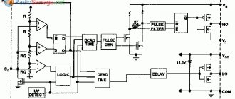
But... wait a minute. This circuit is somewhat reminiscent of the same circuit of a Simple Power Supply. Well, yes, this is the same scheme ;-). There are just some nuances here. The main trump card in this scheme is the stabilizer regulator LM350 or LM338. What is the specialty of these stabilizers? And why did we replace the good old LM317?
So, we are looking for datasheets (these are technical descriptions of radio components) for stabilizers LM317, LM350 and LM338. I know that you are all lazy, so I have already tried for you and found their main parameters:
LM317 - can deliver current to the load, and at the same time not flicker with a bright flame, about 1.5 Amperes. No... that's not enough.
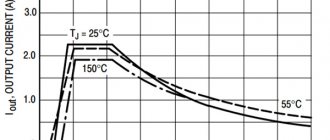
LM350 - can deliver a current of 3 Amperes . Mmm, that's better.
LM338 – can deliver a current of about 5 Amps ! Well, this is already a really powerful thing!
But again, there is one thing: all stabilizers must be installed on a radiator, otherwise they will die from overheating. The datasheet says that they are protected from short circuits and overheating, but I still don’t trust these protections. If it shorts at a current of 5 Amps, the microcircuit will fly to the other world to the burnt transistors.
For powerful power supplies, a powerful diode bridge will be required. Therefore, it is better to take the KVRS5010 diode bridge
which can be bought cheaply on Ali using this link. If the toad is still strangling, then you can assemble it from powerful diodes, which you still have to buy, which will cost more.
My build
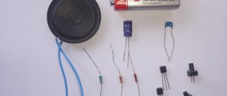
It's time to test this whole thing in practice. I think you yourself understand that I assembled the power supplies from scrap materials. First of all, I found a future blank for the board and tore out all the unnecessary radio components from there.
Four diodes turned out to be very useful, those on the bottom left, two capacitors of decent capacity and a radiator on the top right. Just what we need!
So diodes KD203A. You can use any others, as long as they can withstand the current passing through them. I did not redo the board and left these diodes.
Two capacitors. One is 2000uF, and the other is 100uF. In principle, the larger the capacitor after the diode bridge, the better. 2000 uF, I think, will be quite enough. We make sure that the voltage on the capacitors does not exceed the voltage that is written on them. In my case, I took capacitors that can easily operate in circuits up to 50 Volts.
The next step is to select a POWERFUL (!) transformer for 220—–>15-25 Volts. Don’t even think about putting a transformer there from your radios, Chinese toys and other small equipment. In short, the larger the transformer, the better. We have a bunch of these transformers at work, so the issue of selecting the right transformer immediately went to the side:
First of all, we look at the passport data of the transformer. So, everything here is elementary and simple. Where there are the most turns is the primary winding. Next, we connect this primary winding to a 220 Volt network and measure the voltage on the secondary windings. We look at where there is a voltage that suits us (well, that is, from 15 to 25 Volts).
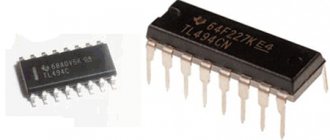
The transformer was picked up. Now all that remains is to select the microcircuit. Since I made this power supply for small speakers, it means that the radio will consume little current. I think no more than 3 Amps. Therefore, we will use the LM350 stabilizer:
We will carefully prepare a place for him. To do this, take fine-grained sandpaper and clean the place for our stabilizer.
Lubricate the LM with heat-conducting paste KPT-8
We clamp it onto the radiator. This completes the most difficult process