The human ear is capable of distinguishing a fairly large range of frequencies, which is called the audio range. It occupies a band from 20 Hz to 20 kHz. Depending on individual perception characteristics, the sound range may be somewhat limited in the lower and upper parts. There are no dynamic loudspeakers in speaker designs that correctly reproduce the entire audio frequency band.
This is due to physical and mechanical factors. Thus, the diffusers of low-frequency speakers are large, so the acoustic resonator, due to its large inertia, cannot respond to vibrations with a frequency of 10-20 kHz. For high-quality playback, the entire audio frequency band is divided into three sub-bands:
- Low frequencies – 20 Hz-200 Hz
- Mid frequencies – 200 Hz-5 000Hz
- High frequencies – 5,000 Hz-20,000 Hz
Characteristics, purpose
A crossover is a special piece of equipment included in a speaker system, the main function of which is to prepare the required frequency range for each speaker. As you know, any speaker system is designed for a specific operating frequency range. If the signal supplied to the speaker exceeds the range limits, the sound may be distorted.
Under normal conditions, the function of tweeters is to reproduce sounds only at high frequencies. Low-frequency speaker systems operate separately. Sometimes they are even installed in different places in the cabin. The same goes for mid-frequency sounds. They are fed only to the speaker that produces mid frequencies.
Therefore, for high-quality reproduction of music tracks in a car, it is necessary to select certain frequencies and feed them strictly to specific speakers. This is why you need a crossover for acoustics.
Connection instructions
A passive crossover for car audio is connected as follows:
- Speakers are purchased and installed.
- The output wires for the speakers from the radio are connected to the input terminals of the device.
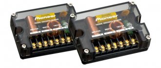
- The speakers are connected using speaker cables to the corresponding terminals of the device, which may be designated Wf (for a full-range speaker), Sw (for a subwoofer), Mw (for a midwoofer) and Tw (for a tweeter).
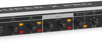
To simplify setup and connection, car amplifiers with a built-in crossover are selected. The subwoofer, midwoofers and tweeters are connected to the corresponding outputs of the audio device. The switches select the characteristics most suitable for the selected speakers.
How it works
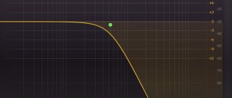
The design of the device is quite simple. These are two frequency filters that work according to the following principle. So, when the crossover frequency is 1000 Hz, one of the two filters will select frequencies that are lower than this value. The second filter will work with a frequency band above the mark. Filters have their own names. Low pass is designed to work with low frequencies up to 1000 Hz. The hi-pass will only handle frequencies above 1000 Hz.
Two-way devices operate on this principle. However, there is also a three-way crossover on the modern market. The main difference here is another filter that can handle mid-range frequencies from 600 to 1000 Hz.
More channels for filtering audio frequencies and feeding them to speakers corresponding to these frequencies leads to higher quality sound inside the car.
Criterias of choice
When choosing a crossover, you need to carefully study the technical specifications. There are separate devices on the market that are designed only for the subwoofer or tweeters. If the user plans to install 2 amplifiers in the audio system, it is recommended to select 3-channel crossovers with outputs for a subwoofer and speakers.
One of the most important parameters is the slope of the filter, or the order of the cutoff frequency. To be able to place a subwoofer in a car, the roll-off slope must be at least 18 dB. Otherwise, the subwoofer will produce distorted sound.
For a narrowband subwoofer, it is recommended to use a crossover with an attenuation characteristic of up to 12 dB. The signal cutoff frequency will vary between 75-150 Hz. It would be desirable for this range to have a 3-step adjustment. Better results are shown by the smooth adjustment of the cutoff, which allows you to easily and quickly adjust the cutoff frequency for the subwoofer. If the tweeters are driven with higher quality crossovers than the subwoofer, the sound experience will be negatively affected.
- How to properly set up music in the car
- Why does the radio get hot?
- Why does the radio stutter?
- How to properly configure the Navitel navigator for a car
Technical features of crossovers
Most modern devices are inductors and capacitors. Depending on the number and quality of manufacturing of these elements, the cost of the product is formed.
Why does an acoustic crossover include a capacitor and a coil? These are the simplest reactive parts. They can handle various audio frequencies without much expense.
The number of reactive parts affects the filter capacity: 1 – one element is used, 2 – two elements. Depending on the number of reactive parts, as well as the crossover network, the system filters differently those frequencies that are not suitable for specific channels. It can be assumed that the more reactive elements there are in the circuit, the better the crossovers of the speaker systems will filter the signal. Filtering schemes have a certain characteristic. This is the so-called “slope slope”. In other words, it is sensitivity. Depending on the level of the “steepness of the decline,” all products on the market can be divided into models of the first, second, third and fourth classes.
Between Thiel and Videoton
The answer to the first question: a long time ago. I was unable to establish who came first, but there were two vague memories. First: I saw a sequential crossover diagram in an ancient (even then) amateur radio reference book, which gave me material for thought while studying in high school (this is deep in the last century). Second: I saw the same one in the instruction manual for Videoton speakers (130 rubles per pair, it was a robbery back then) and already, it seems, as a student, I marveled at the wit of the scheme. The fame of such filters was brought to them by a well-known gentleman named Richard Small. At the turn of the 60s and 70s (that is, significantly after the reference book, approximately simultaneously with “Videoton” and obviously, by the way, before a series of publications after which the concept of “Thiel-Small parameters” appeared) he made a report at the Audio session Engineering Society about the interesting details of the behavior of such filters, which revived interest in them.
Rice. 3. Frequency response of first-order crossovers
The second question will receive the following answer: yes, although it is not immediately noticeable. I will give two frequency response graphs (Fig. 3), both obtained for the filters shown in Fig. 1 and 2, for clarity, here and further we will assume that the crossover frequency is 1 kHz. I know that they don’t make such things, I repeat - for clarity. You say there is one schedule? No, two completely overlapping each other. There will be no difference in the frequency response if the values of the filter elements are chosen the same, according to the formulas for parallel first-order filters with the Butterworth characteristic (and such filters, even if you crack them, will not have another). The formulas are known to the court, but so that you don’t run around and I don’t have to refer them later:
L = Rн/(2π Fo)
С = 1/(2π Fo Rн).
With a load resistance Rн of, say, 8 ohms and a crossover frequency, as agreed, of 1 kHz, we obtain ratings of 1.27 mH and 20 μF. Please note: in this absolutely ideal case, the total frequency response of the crossover (black line) is strictly horizontal for both filters. The ideal, as we know, is unattainable. How will such crossovers behave under a real load with an impedance that depends on frequency? For the purposes of this essay, I have compiled equivalent LF and HF drivers with fairly typical parameters expected in real life.
Rice. 4. Impedance of real load equivalents
In Fig. 4 - their impedance curves. What is typical: a hypothetical midbass is a head with a resonant frequency of about 70 Hz (which, in general, doesn’t matter now) and a fairly high voice coil inductance. But this is important and typical for diffuser bass/midrange heads. I conditionally took the tweeter with a resonant frequency of 650 Hz, which is convenient for our experiments; it is only 2/3 of an octave lower than the planned crossover frequency. The resonant peak is like a tweeter without ferrofluid damping, this is an aggravating circumstance for a crossover, inductance is moderate, in practice it is often even lower.
Rice. 5. Parallel crossover on real load
How will our twin filters work under such a load? This is where they stop being twins. In Fig. 5 - frequency response of parallel crossover links and the result of their summation, the dotted line shows how it should have been ideally. In real life, a hump appeared on the frequency response of the high-pass filter at the resonance frequency of the tweeter, it was immediately reflected in the total frequency response, but that would be nothing. Look how much the efficiency of the low-pass filter has fallen because the impedance of its load (midbass voice coil) increases with increasing frequency. The slope of the frequency response decline, which was already small, decreased further, and already an octave after the crossover frequency, filtering as such stopped. The total frequency response, as is easy to see, is tears and nothing more. Yes, many here will say: that’s why Zobel circuits were invented, to compensate for the inductance of the head; for low-order filters without Zobel, there are faucets. But we still have one inductance and one capacitance, so let’s try to do something while remaining within the framework of this arsenal. Here is the same set of frequency response, but for a sequential filter (Fig. 6).
Rice. 6. Series crossover on real load
Look, a completely different calico, why, you ask? And therefore: what was an obstacle to the operation of a parallel filter became a factor in increasing the efficiency of a sequential one. The inductance of the low-frequency head interfered, and here, if we return to our analogy with taps that pass (or delay) various frequency components, when the midbass resistance increases with increasing frequency, the signal is even more willing to bypass, through the capacitance. Why doesn't this happen in the beeper circuit, where the effect would be the opposite? Yes, because in real life there are no tweeters with high inductance.
And now - the most important thing: how did the total frequency response change when replacing resistors with the equivalent of real heads? But no way. This is the main property of serial filters, hence the name of Small’s historic report: “Constant-Voltage Crossover Network Design.” Under any circumstances, the sum of the voltage on the midbass and the tweeter will be equal to the input, that is, the voltage at the output of the amplifier.
Let's do the following experiment: let for some reason the load resistance of one of the crossover links turn out to be different from the calculated one. Well, you never know, another speaker was tucked in, or this one’s voice coil resistance increased due to heating. For clarity, we will again return to the ideal, ohmic load, then, if you want, I will show the same thing on a real one.
Rice. 7. Parallel crossover, variable resistive load
In Fig. 7—results of the experiment with a parallel filter. The high-pass filter link does not know anything about what is happening in the neighboring low-pass filter, so its frequency response remains unchanged. And the low-pass filter changes (the curves correspond to a change in load from 6 to 12 Ohms), while the crossover frequency moves, and the total frequency response is far from being as perfect as in the case of the calculated load.
Rice. 8. Series crossover, variable resistive load
We do the same with a serial filter (Fig. 8). Here, a change in the resistance of one of the two loads affects the frequency response in both filter sections, however, the total frequency response stands rooted to the spot due to the already mentioned circumstance. Constant-Voltage, as was said. If you insist, here is the same experience on equivalents of real heads.
Rice. 9. Parallel crossover, variable real load
Rice. 9 - for a parallel crossover, midbass filtering has not improved, and when the ohmic resistance of its voice coil changes, the total frequency response changes very noticeably.
Rice. 10. Series crossover, variable real load
Rice. 10 - case of sequential crossover, other conditions are the same. Within certain (and not catastrophic) limits, both components of the frequency response change; the sum, as before, is flint. As you can see, we already have two practical results. What if we dig some more?
Active and passive equipment
A passive crossover for acoustics is the most common solution. It can often be found in the modern market. As the name suggests, this device does not require additional power to operate. Therefore, it will be much faster and easier for the car owner to install sound equipment. The disadvantage of this group of devices is that simplicity is not always a guarantee of quality.
Due to the passive circuit, the system takes part of the energy to ensure the operation of the filter. At the same time, the reactive parts change their phase shift. Naturally, this is far from the most serious drawback. However, it will not be possible to perform frequency correction as finely as possible.
Preparatory work: how to remove the trim
Before carrying out work, turn off the ignition and disconnect the negative cable from the battery. Then do this:
- Often there is no speaker panel, and the speakers are hidden behind a non-removable mesh (grid) of the door trim. In this case, remove the door handles that interfere with dismantling. If there are fastenings with self-tapping screws, remove the protective plugs and unscrew the screws. Then remove the trim.
Slowly rocking, remove the panel, releasing one fastener after another.
Remove door handles and other body parts that interfere with dismantling
How to calculate correctly with your own hands?
Calculating the crossover for acoustics is an important process. No manufacturer has yet been able to produce an ideal speaker system that could reproduce high-quality sound in a different range. Subwoofers are used for low frequencies. For medium speakers, mid-range speakers are used. But when this whole complex begins to sound, some confusion may arise. This is why a crossover is needed in acoustics - so that a signal of only a certain frequency is sent to a specific speaker system.
How to connect speakers to the front or back door
It happens that the new column, coinciding with the old one in diameter, does not “sit” on the standard podium (ring or protrusion) or turns out to be thicker and begins to stick out too much. Sometimes the stand is completely missing. In this case, proceed as follows:
- Install a new podium: it is necessary in order to raise the speaker if the latter rests on the door mechanisms. It also plays the role of a rigid and elastic support for the diffuser, improves the radiation pattern, preventing sound from “escaping” under the casing. You can buy the podium in the same place as the speakers, or make it yourself.
- Use suitable plastic housings from faulty speakers as a base, or use a jigsaw to make a podium out of plywood. If necessary, cut out several rings and glue them together.
It is advisable to impregnate a wooden podium with a protective compound and cover it with a sealant
Video: how to install acoustics on a car
Why do you need a crossover for car acoustics?
Why are speaker crossovers needed? A crossover or bandpass filter is a device that limits the frequency band sent to a particular loudspeaker. A good quality speaker system consists of three dynamic heads and each of them transmits its own frequency band. The tweeter or high-frequency head is small in size and has a lightweight diffuser. It is located at the top of the speaker system. The midrange driver has a larger diameter, and the bass driver, the largest speaker, is located at the bottom of the speaker. A crossover for speakers is needed in order to highlight a certain frequency band and cut off or greatly attenuate the rest of the frequency range. This significantly increases the high fidelity of music recordings.
The car interior is a closed space of relatively small volume, in which it is difficult to achieve high-quality sound reproduction. In addition, the interior decoration can be made using soft sound-absorbing materials, so frequency division of the sound signal into three separate bands in the car is necessary. What do crossovers give to speakers in the passenger car interior. Frequency filters allow you to obtain the correct configuration of the speakers in the car and achieve high-quality sound, both bass and high frequencies. Crossovers are often built directly into speaker systems.
How to remove a standard speaker and attach a new one
Further work will require patience and attentiveness from you. Only compliance with the sequence of actions below guarantees correct installation of the speakers.
- Once you have access to the speaker, unscrew the fasteners and pull the speaker out towards you. Disconnect the connector with wires.
Unscrew the fasteners and pull the speaker towards you. Disconnect the connector with wires
It is advisable to cover the door (the area of the door near the speaker) with sound insulation, vibroplast or something similar
Crossover speakers, what is it?
Crossovers for speakers are either passive or active. Passive systems are LC filters of the first second or third order, which is determined by the number of filter sections. The first-order filter provides a signal attenuation rate of only 6 dB per octave, second- and third-order filters provide 12 and 18 dB, respectively. For use in car sound systems, it is recommended to use second-order crossovers. This is due to the acoustic characteristics of the car interior. Crossovers use film capacitors and inductors wound without cores or using ferromagnets.
Crossovers are devices in sound systems that create the desired operating frequency ranges for speakers. Speakers are designed to operate within a specific frequency range. They do not accept frequencies outside these limits. If a low frequency is applied to the high-frequency speaker (tweeter), the sound picture will deteriorate, and if the signal is also powerful, the tweeter will “burn out.” High-frequency speakers should only handle high frequencies, and woofers should only receive the low-frequency range from the overall audio signal. The remaining middle band goes to mid-range speakers (midwoofers). Therefore, the task of crossovers is to divide the audio signal into the desired (optimal) frequency bands for the corresponding types of speakers.Simply put, a crossover is a pair of electrical filters. Let's say the crossover has a cutoff frequency of 1000 Hz. This means that one of its filters cuts off all frequencies below 1000 Hz and only allows frequencies above 1000 Hz to pass through. This filter is called a high-pass filter. Another filter that passes frequencies below 1000 Hz is called low-pass. Graphically, the operation of this crossover is presented in Figure 3. The intersection point of the two curves is the crossover cutoff frequency equal to 1000 Hz. Three-way crossovers also have a mid-frequency filter (band-pass), which passes only the middle frequency range (approximately 600 Hz to 5000 Hz.) Figure 4 shows the frequency response of a three-way crossover.
Crossover sensitivity order
Order of sensitivity is the ratio of the output signal intensity (dB) of the crossover to the input signal frequency, assuming that the input signal intensity is constant. Typically, sensitivity (cutoff slope) is characterized as the ratio dB/octave. For many mathematical reasons, crossover sensitivity is always a multiple of 6 dB/octave. The first order crossover has a sensitivity of 6 dB/octave. The second order crossover has a sensitivity of 12 dB/octave, the third order has a sensitivity of 18 dB/octave, and the fourth order crossover sensitivity is 24 dB per octave. Consider a third-order low-pass filter with a cutoff frequency of 100 Hz. As mentioned above, this crossover will only pass frequencies below 100 Hz, and will cut off frequencies above 100 Hz. Frequency cutting will occur as follows: all frequencies above 100 Hz will lose their intensity at the output of the filter by a multiple of 18 dB, depending on the octave they belong to. That is, the 200 Hz frequency (the first octave above the cutoff frequency) will lose its intensity by 18 dB, the intensity of the 400 Hz frequency (the second octave) will fall by 36 Hz, and the third octave (800 Hz) will attenuate by 54 dB. And so on, all subsequent octaves will be attenuated by a multiple of 18 dB. A less sensitive first-order low-pass filter with a cutoff frequency of 100 Hz will do the same thing, only unnecessary octaves will be attenuated not by 18 dB, but by 6 dB. As you can see, the filters that make up the crossovers cannot immediately cut off unnecessary frequencies, but do it gradually, with different sensitivities depending on their order.
Crossovers of the first order
- This is the simplest passive crossover, which consists of one capacitor and one inductor. The capacitor acts as a high-pass filter to protect the tweeter from unnecessary low and mid frequencies. The coil is used as a low-pass filter. The sensitivity of first-order crossovers is low - only 6 dB per octave. A positive feature of these crossovers is the absence of phase shift between the tweeter and the other speaker.
Second-order crossovers
. They are also called Butterworth crossovers, named after the creator of the mathematical model of these crossovers. Structurally, they consist of one capacitor and coil on the tweeter and one capacitor and coil on the woofer. They have a higher sensitivity of 12 dB per octave, but give a phase shift of 180 degrees, which means that the tweeter and other speaker membranes are not synchronized. To fix this problem, you need to change the polarity of the wires on the tweeter.
Third-order crossovers
. Such crossovers have one coil and two capacitors on the tweeter, while the opposite is true on the low-frequency speaker. The sensitivity of such crossovers is 18 dB per octave, and they have good phase characteristics in any polarity. The downside to third-order crossovers is that they cannot use time delays to correct problems associated with speakers not emitting on the same vertical plane.
Fourth-order crossovers
. Fourth-order Butterworth crossovers have a high sensitivity of 24 dB per octave, which dramatically reduces the interference of speakers in the frequency separation region. The phase shift is 360 degrees, which actually means there is no phase shift. However, the magnitude of the phase shift in this case is not constant and can lead to unstable operation of the crossover. These crossovers are practically never used in practice. Linkwitz and Riley managed to optimize the design of the fourth-order crossover. This crossover consists of two second-order Butterworth crossovers connected in series for the tweeter, and the same for the woofer. Their sensitivity is also 24 dB per octave, but the output level of each filter is 6 dB less than the crossover output level. The Linkwitz-Riley crossover has no phase shifts and allows time correction for speakers that do not operate in the same physical plane. These crossovers provide the best acoustic performance compared to other designs.
Designing Passive Crossovers
As mentioned above, a passive crossover consists of capacitors and inductors. In order to assemble a first-order passive crossover, you need to have one capacitor and one inductor. The capacitor is installed in series with the tweeter (high-pass filter), and the coil is installed in series with the woofer (low-pass filter). The nominal values of inductance ((H - microhenry) and capacitance ((F - microfarads)) are given in the table depending on the desired crossover cutoff frequency and speaker impedance.
1st order crossover (6 dB/octave)
Cutoff frequency
| 4 ohm speaker. Capacitor F | 4 ohm speaker. Coil H | 8 ohm speaker. Capacitor F | 8 ohm speaker. Coil H | |
| 50 Hz | 796.7 | 12.7 | 398.1 | 25.5 |
| 75 Hz | 530.8 | 8.5 | 265.4 | 17.0 |
| 100 Hz | 398.1 | 6.4 | 199.0 | 12.7 |
| 125 Hz | 318.5 | 5.1 | 159.2 | 10.2 |
| 150 Hz | 258.4 | 4.2 | 132.7 | 8.5 |
| 175 Hz | 227.5 | 3.6 | 113.7 | 7.3 |
| 200 Hz | 199.0 | 3.2 | 99.5 | 6.4 |
| 225 Hz | 176.9 | 2.8 | 88.5 | 5.7 |
| 250 Hz | 159.2 | 2.5 | 79.1 | 5.1 |
| 275 Hz | 144.8 | 2.3 | 72.4 | 4.6 |
| 300 Hz | 132.7 | 2.1 | 66.3 | 4.2 |
| 400 Hz | 99.5 | 1.6 | 49.8 | 3.2 |
| 500 Hz | 79.6 | 1.3 | 39.8 | 2.5 |
| 600 Hz | 66.3 | 1.1 | 33.2 | 2.1 |
| 700 Hz | 56.9 | 0.9 | 28.4 | 1.8 |
| 800 Hz | 49.8 | 0.8 | 24.9 | 1.6 |
| 900 Hz | 44.2 | 0.7 | 22.1 | 1.4 |
| 1000 Hz | 39.8 | 0.6 | 19.9 | 1.3 |
| 1100 Hz | 36.2 | 0.6 | 18.1 | 1.2 |
| 1200 Hz | 33.2 | 0.5 | 16.6 | 1.1 |
| 1300 Hz | 30.6 | 0.5 | 15.3 | 1.0 |
| 1400 Hz | 28.4 | 0.5 | 14.2 | 0.9 |
| 1500 Hz | 26.5 | 0.4 | 13.3 | 0.8 |
| 1600 Hz | 24.9 | 0.4 | 12.4 | 0.8 |
| 1700 Hz | 23.4 | 0.4 | 11.7 | 0.7 |
| 1800 Hz | 22.1 | 0.4 | 11.1 | 0.7 |
| 1900 Hz | 21.0 | 0.3 | 10.5 | 0.7 |
| 2000 Hz | 19.9 | 0.3 | 6.6 | 0.4 |
| 3000 Hz | 13.3 | 0.2 | 6.6 | 0.4 |
| 4000 Hz | 10.0 | 0.2 | 5.0 | 0.3 |
| 5000 Hz | 8.0 | 0.1 | 4.0 | 0.3 |
| 6000 Hz | 6.6 | 0.1 | 3.3 | 0.2 |
| 7000 Hz | 5.7 | 0.1 | 2.8 | 0.2 |
| 8000 Hz | 5.0 | 0.1 | 2.5 | 0.2 |
| 9000 Hz | 4.4 | 0.1 | 2.2 | 0.1 |
| 10000 Hz | 4.0 | 0.1 | 2.0 | 0.1 |
For example, let’s select capacitance and inductance for a crossover with a cutoff frequency of 4000 Hz and a speaker impedance of 4 ohms. From the above table we find that the capacitance of the first order capacitor should be equal to 10 mF, and the inductance of the coil should be 0.2 mH. To determine the nominal values of the components for a second-order crossover (12 dB/octave), it is necessary to multiply the values from the same table for the capacitor by a factor of 0.7, and multiply the value for the inductor by a factor of 1.414. We must remember that for a second-order crossover, two capacitors and two inductors are needed. Let's create a second-order crossover for a cutoff frequency of 4000 Hz. To determine the values for both capacitors, multiply the value from the table 10 mF by a factor of 0.7 and get 7 mF. Next, we multiply the inductance value of 0.2 mH by a coefficient of 1.414 and get an inductance value of 0.28 mH for each coil. One of these capacitors is installed in series on the tweeter, and the second in parallel on the woofer. One coil is in parallel for the tweeter, and the other is in series for the woofer.
Passive and active crossovers
The difference between these two types of crossovers is very simple. An active crossover requires an external power supply, while a passive crossover does not. Because of this, an active crossover takes place in the sound system before the amplifier, processing the audio signal from the preamplifier of the head unit (for example, a car radio). Next, after the active crossover, two or three power amplifiers are installed. In this case, one amplifier is not installed, since there is no point in combining the signals separated by an active crossover into a single signal in the amplifier. The separated signals must be amplified separately. As you can see, active crossovers are used in expensive high-quality sound systems. Passive crossovers process an already amplified signal and are installed in front of the speakers. The capabilities of passive crossovers are limited compared to active ones, but their correct use can give good results with minimal financial costs. Passive crossovers perform well when order of magnitude sensitivity requirements are less than 18 dB per octave. Above this limit, only active crossovers work well.
Passive crossovers are mainly used to process the signal of tweeters and midrange speakers. These crossovers can be used for low-frequency speakers, but the demand for the quality of capacitors and inductors sharply increases, which leads to their rise in price and increase in size. Passive crossovers do not tolerate overloads well. Peak signal intensities coming from the amplifier can change the cutoff frequency of the filters. In addition, an overloaded filter weakens the audio signal (damping). Therefore, when choosing passive crossovers, pay attention to their ability to withstand peak loads created by the amplifier. Active (or electronic) crossovers are a variety of active filters that can be controlled and easily change the cutoff frequency of any channel. The sensitivity of active crossovers can be any order, from 6 dB to 72 dB per octave (and higher). Basically, active crossovers for car audio systems have a sensitivity of 24 dB per octave. With such sensitivity, frequency exchange between speakers is practically eliminated. The sound picture is very high quality. The only drawback of active crossovers is their high cost compared to passive ones.
Phase shift
Now let's talk about phase shifts that can occur in sound systems that use crossovers. Phase shift is an inevitable phenomenon resulting from the design features of high-pass, low-pass and band-pass filters. Phase is the temporal relationship between two signals. The phase is measured in degrees from 0 to 360. If two identical speakers emit sound waves in opposite phase (180 degree phase shift), then the sound is attenuated. The problem is resolved by changing the polarity on one of the speakers. When the acoustic system consists of different speakers operating in different frequency ranges (tweeter and midwoofer), then eliminating the phase shift is not always solved by simply changing “+” to “-“. The wavelength from the tweeter is shorter than from the midwoofer. Therefore, the high-frequency wave front may reach the listener later (or earlier) than the mid-frequency (or low-frequency) wave front. This time delay is a consequence of the phase shift. In this case, the sound picture can be optimized by physically aligning the two speakers relative to each other in the vertical plane until the sound picture is improved. For example, at a wave frequency of 1000 Hz, a time delay of one millisecond is eliminated by moving the speakers relative to each other by 30 cm.
Setting up an active crossover
The most important thing in setting up a crossover is choosing the right cutoff frequency. If we have a three-way active crossover, then we are faced with the task of determining two cutoff points (frequencies). The first point determines the cutoff frequency for the subwoofer (low-pass) and the beginning of the mid-frequency range for the midwoofer (high-pass). The second point determines the end frequency of the mid-range (low-pass) and the starting frequency of the high-frequency range for the tweeter (high-pass). The most important thing is that when setting crossover cutoff frequencies, remember the frequency characteristics of the speaker and under no circumstances load the speaker with frequencies that are not within its operating range. For example, if the subwoofer rattles a little or makes a hum (unpleasant resonance of the car body), then it is overloaded with unwanted mid frequencies (above 100 Hz). Move the cutoff frequency (low-pass) to 75 Hz and/or set the sensitivity to 18 dB or 24 dB per octave, if possible. Let us recall that increasing the order of the crossover sensitivity (dB/octave value) cuts off unnecessary frequencies more efficiently, preventing them from leaking through the filter. The sensitivity of high-pass filters for a midwoofer can be left at 12 dB/octave (for “soft” mid-frequency speakers). This active crossover setup is called asymmetrical.
| Speaker type | Cutoff frequency | Cutoff frequency |
| high-pass @ 4,000 Hz | ||
| Midrange din. (midrange) | high-pass @ 500 Hz | low-pass @ 4,000 Hz |
| Bass speaker (midbass) | high-pass @ 100 Hz | low-pass @ 500 Hz |
| Subwoofer | low-pass @ 100 Hz |
This table shows the starting cutoff frequencies for various types of speakers when configuring active crossovers.
Built-in crossover in dynamics
If industrial speakers are installed in a car, then, as a rule, they are already equipped with built-in frequency filters. They use capacitors and inductors. Often, to match the resistance of the loudspeaker and low-frequency amplifier, fixed resistors are placed in the filters.
The classic universal second-order crossover is designed to work with three-way speaker systems and provides a frequency suppression slope of 12 dB per octave. When repeating the design, it is not recommended to install electrolytic capacitors in the filter, but to use film capacitors specifically designed for use in acoustic system filters. Usually, radio amateurs purchase expensive foreign-made capacitors, but it is quite possible to get by with domestic K73-16. The best option for acoustic crossovers would be to use axial polypropylene capacitors K78-34, which are specially designed for use in high-end acoustic systems.
When installing a modern stereo system in a vehicle, the owner needs to choose the right crossover. This is not difficult to do if you first become familiar with what it is, what it is intended for, and as part of which speaker system it will work.
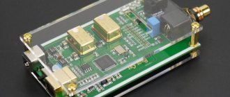
Design and principle of operation
The crossover is assembled on the basis of a small-sized printed circuit board, which has points for connecting the incoming cable. The product is equipped with several pairs of outputs that allow you to connect speakers to reproduce low, mid and high frequency ranges. The number of outputs depends on the number of filters used. The equipment design includes inductors and capacitors that provide separation of frequency intervals.
Structurally, the crossover is a double electric filter. If the device is designed for a cutoff frequency of 2000 Hz, then the primary filter provides cutting of the lower part of the range; secondary - skipping frequencies up to 2000 Hz, cutting off the higher range. The intersection of the frequency curves from the filters gives the cutoff frequency. There are devices equipped with a mid-range filter that removes sounds from music in the frequency range from 600 Hz to 5 kHz.
There are 4 types of crossovers:
- First-level products are assembled on the basis of a capacitor and a coil. Provide trimming of low- and mid-frequency signals in the twitter switching circuit. Due to the simplified design, there is no phase shift between the loudspeakers.
- Butterworth, or second-level, crossovers are designed to transmit the signal to the tweeter and subwoofer. The equipment supports a 180° phase shift, which disrupts the synchronous movement of the membranes in the speakers. To eliminate the negative effect, it is necessary to reverse the polarity of connecting the cables to the Twitter.
- The third level nodes are equipped with 1 coil and 2 capacitors for the high-frequency loudspeaker and a reverse circuit for the low-frequency loudspeaker. The equipment provides high phase parameters regardless of the polarity of the speakers. The products do not allow the use of time delays to improve the sound of acoustics in a car.
- Level 4 crossovers provide a 360° phase shift, which eliminates the negative acoustic effect. The shift value is unstable, which leads to crossover malfunctions.
Purpose
A crossover is a special device in the structure of the speaker system, designed to prepare the required private range for each of the installed sound speakers. The latter are designed for operation within certain frequency ranges. If the frequency of the signal supplied to the speaker goes beyond the range, it can lead, at a minimum, to distortion of the reproduced sound, for example:
- if the frequency is applied too low, the sound picture will be distorted;
- when applying too high a frequency, the owner of a stereo system will face not only sound distortion, but also failure of the tweeter (high-frequency speaker). It may simply not withstand this operating mode.
Under normal conditions, the task of a tweeter is to reproduce only high-frequency sound, and low-frequency sound, respectively, low-frequency sound. The mid-frequency band is fed to the midwoofer - the speaker responsible for the sound of mid-frequencies. Based on the above, in order to reproduce car audio with high quality, you need to select the appropriate frequency bands and feed them to specific speakers. To solve this problem, a crossover is used.
Crossover device
Structurally, the crossover includes a pair of frequency filters that operate as follows: for example, if the crossover frequency is set to 1000 Hz, one of the filters will highlight frequencies below this indicator. And the second is to process only the frequency band exceeding a given mark. Filters have their own names: low pass - for processing frequencies below a thousand hertz; high pass – for processing frequencies above a thousand hertz.
So, the principle by which a two-way crossover works was presented above. There are also three-way products on the market. The main difference, as the name implies, is the third filter, which processes the mid-frequency band, from six hundred to five thousand hertz.
Essentially, increasing the sound band filtering channels and then feeding them to the appropriate speakers leads to higher quality and natural sound reproduction inside the car.
Technical features
Most modern crossovers contain inductors and capacitors. Depending on the quantity and quality of manufacturing of these reactive elements, the cost of the finished product is determined.
Why are coils and capacitors included in a bandpass crossover? The reason is that these are the simplest reactive elements. They process different frequencies of the audio signal without much difficulty.
Capacitors can isolate and handle high frequencies, while coils are needed to regulate low frequencies. By using these properties wisely, the result can be the simplest frequency filter. There is no point in delving into the complex laws of physics and citing formulas as examples. Anyone who wants to become more familiar with the theoretical foundations can easily find information in textbooks or the Internet. It is enough for specialized specialists to refresh their memory about the operating principle of LC-CL type networks.
Putting things in order
A lot has been written about passive filters, even more has been rewritten, everyone knows everything in general terms. There are first order, second and so on. Which to choose? Here, clans of “sharp-pointed” and “blunt-pointed” have long been formed, both of them are right and wrong at the same time, all according to acoustic circumstances. The “pointers” say: “Let’s divide the bands between low-frequency and high-frequency emitters as radically as possible, so that each one does only his own business.” The approach is completely logical: the more decisively (and therefore with a greater steepness of the characteristic, and therefore with a filter of a higher order) the band of the signal connected, say, to the midbass is limited (we will call it midbass everywhere, because it is the shortest, although from the above and what will become clear below, it follows that this will most likely be a mid-range driver), the less dirty tricks associated with the zone mode of operation of the diffuser will come out, in particular, the upper, “Kevlar” resonance of hard diffusers will be suppressed. The steeper the frequency response of the high-frequency filter feeding the tweeter with a signal, the fewer signal components with a frequency close to its own resonance will fall on it, where the high-frequency head produces maximum distortion. And most importantly, the band where the heads emit together, and where the result of such joint work is least predictable, the narrower the higher the steepness of the applied filters. In general, complete harmony of the capitalist model should be established: everyone is busy with their own business, does not interfere with others, and meets with a colleague from another frequency department only during the lunch break, which is so short that there is no time for a conflict to develop.
“What about the phase? - the “blunt-headed people” usually shout at this point. “They’re turning the phase!” Most often, intelligible protest actions are limited to these two cries; the answer to the counter question “so what?”, as a rule, is given in sign language, from which one can only understand what has already been said: they are twisting, you bastards, you can’t do that. Yes, indeed, the higher the order of the filter, the faster the phase shift at the filter output changes near the crossover frequency. "So what? — the “pointed points” stand their ground. “We then minimized the area of joint operation of the heads, where the difference in the phases of their radiation matters. And outside the “lunch break” the concept of absolute phase comes into force, which the inhabitant of the Earth does not perceive by ear.” Hence: in the camp of the “sharp points” there are very strong political figures. For example, I already once cited Phoenix Gold as an example of elite acoustics (“AZ” No. 9/2002, that was when it happened), all the top models of CDT Audio, later EOS Opera, and Siegfried Linkwitz, half of whose name became half the name of famous Linkwitz-Riley filters, he doesn’t want to hear anything less than fourth order.
Here, however, the “blunt-ends” take out a hefty cobblestone from their bosoms, which is difficult and painful to argue with. It has been proven by smart people: only first-order filters correctly transmit a rectangular pulse. And for the sake of this (and whoever raised their eyebrows now, I hope there are few of them - it is very important) adherents of soft filtering are ready to endure the hardships and hardships associated with unsatisfactory filtering of out-of-band radiation. And a wide range of heads working together in a two-way (as we agreed) system. But the even smarter ones among the simply smart ones add: good impulse characteristics of two-way acoustics with first-order filters are realized only if the radiation is temporally correct. That is, when the centers of radiation from the LF and HF heads are at least close to each other, or optimally, they are placed so that the distance from the centers of radiation to the ears, tormented by incoherence, is the same.
To be fair, we also have someone to present, the most famous supporters of the full or partial use of first-order filters in car acoustics are Dynaudio, Morel and Eton. Sit, sit, no need for ceremony...
Now we have a practical answer to both irreconcilable clans at the same time: when bandpass emitters are far from each other, first-order filters have no advantages, only disadvantages. And when it’s close, they have it. And this is exactly the case of “our” automobile three-way systems. When the bass player is down there, and the midrange/high frequencies are at the stand, pressed against each other. In this case, good (emphatically) passive filters of the first order could (dreamingly) breathe new life into the undeservedly (due to reluctance to tinker) forgotten concept of a point emitter, in the manner of, say, Morel Integra or (to a lesser, but far from zero degree) of some 4-inch coaxials, the emitters of which are very good (individually), but together they are horror or, at most, semi-horror, because there are no filters, sometimes literally. Now let's find out whether it is possible to make a good first-order filter. For this…
Differences between active and passive crossovers
Let's start the comparison with a passive crossover. It is known from practice that the passive crossover is the most common and most often found type on the market. Based on the name, you can understand that passive ones do not require additional power. Accordingly, it is easier and faster for the vehicle owner to install the equipment in his car. But, unfortunately, speed does not always guarantee quality.
Due to the passive principle of the circuit, the system needs to take part of the energy from the filter to ensure its operation. In this case, reactive elements tend to change the phase shift. Of course, this is not the most serious drawback, but the owner will not be able to fine-tune the frequencies.
Active crossovers allow you to get rid of this disadvantage. The fact is that, although they are much more complicated than passive ones, the audio stream in them is filtered much better. Thanks to the presence of not only coils and capacitors, but also additional semiconductor elements, the developers were able to significantly reduce the size of the device.
They are rarely found as separate equipment, but any car amplifier contains an active filter as an integral part. Due to the passive principle of the circuit, the system needs to take part of the energy from the filter to ensure its operation. In this case, reactive elements tend to change the phase shift. Of course, this is not the most serious drawback, but the owner will not be able to fine-tune the frequencies.
Active crossovers allow you to get rid of this disadvantage. The fact is that, although they are much more complicated than passive ones, the audio stream in them is filtered much better. Thanks to the presence of not only coils and capacitors, but also additional semiconductor elements, the developers were able to significantly reduce the size of the device.
They are rarely found as separate equipment, but any car amplifier contains an active filter as an integral part.
Types of car crossovers
There are two main types of crossovers, each best suited for specific situations:
- Passive crossovers are located between the amplifier and speakers. Filters out unwanted frequencies. Some speakers have built-in passive crossovers. Because these crossovers simply connect between the amplifier and speakers, they are relatively easy to install. However, there is a certain degree of inefficiency inherent in passive crossovers.
- Active crossovers. They are also known as electronic crossovers. They are more complex and more expensive than passive ones. Active crossovers require power supplies, but do not waste energy by filtering amplified signals like passive devices do.
Settings Features
In order to get high-quality car audio as a result, you need to choose the right cutoff frequency. When using an active three-way crossover, two cutoff frequencies must be determined. The first point will mark the line between low and medium frequencies, the second - the line between medium and high. Before connecting a crossover, the car owner must always remember that it is necessary to correctly select the frequency characteristics of the speaker.
In no case should you apply frequencies to them at which they simply cannot operate normally. Otherwise, this will not only lead to deterioration in sound quality, but also to a reduction in service life.
Passive crossover connection diagram
How to connect speakers in two-piece systems
Approximately 80% of car enthusiasts who install component sound systems are limited to installing additional tweeters. For some, this is not enough, since achieving the highest sound quality is impossible without “drawing” the lower frequencies of the sound spectrum to the point of the limits of human hearing.
Obstacles to the propagation of vibrations of the lowest frequencies degrade the quality slightly. Therefore, huge subwoofers operating in the lower sound band are placed in the trunk or on the rear parcel shelf.
A component car audio system can contain from 2 (including tweeter) speakers per channel to 4, 6 or more
Thus, a component car audio system can contain from 2 (including tweeter) speakers per channel to 4, 6 or more. Practical implementation depends on the aesthetic requirements of the car owner, his desire to spend money and time to achieve them.
Scheme of channel-by-channel connection of speaker components
All components of the audio system are connected to each other by wires. Weak tweeters can be connected with almost any wire. Subwoofers are a completely different matter. With a power of 100 W, the speaker will require a current of about 8 A. To avoid mistakes, it is best to use a specialized speaker cable with a wire cross-section of at least 2.5 square meters. mm.
To connect the wires to each other and to the speakers, depending on the design features, use standard connectors, terminals or twisting with mandatory soldering
Wires for connecting speakers are laid in inaccessible places, covered under removable casings as far as possible from other wiring harnesses. The sound lines are inserted into the doors through standard rubber accordion covers.
By following the recommendations outlined above, any owner will be able to equip their car with good sound. How many speakers will be used and where exactly they will be installed depends on the design features of the car and the desires of its owner. And the secret of success lies in the availability of the necessary components and accuracy when performing work.