Having read this in a draft, the editor-in-chief said: “What are you talking about, this is the Klondike, let’s dig into it somehow.” "AZ" No. 5/2009, p. 45
The editor-in-chief is me. And Klondike, as you already read in the subtitle, is sequential frequency separation filters. It was promised to dig, so I decided to dig myself.
But before we dig, let's mark the area. “Filters” is a broad concept. Even electric, even frequency-dividing, even passive, even intended for use in acoustic systems. It’s still wider than my native country. We will set the task very specifically, for 6 acres. It is necessary to divide the broadband signal from the output of the amplifier in such a way as to ensure optimal operation of two emitters specializing in reproducing the lower and upper frequencies of the audio range (the same thing, but in short - two-way).
This case, in our age of three-way fronts and processor “heads,” is far from conventional and not academic. Increasingly (and far from being fashionable), experienced craftsmen are leaning toward a 2.5-way front speaker topology. The bass players (somewhere down there) have been filtered by the “head”, processor or amplifier, and with the midrange/high frequency the sacred process begins (and rightly so, it begins), which very often leads to the abandonment of active filtering in this extremely vulnerable part of the sound spectrum . And here the subject of our discussion today is one of the very promising methods of fighting for uncompromising sound. Now - in order...
Putting things in order
A lot has been written about passive filters, even more has been rewritten, everyone knows everything in general terms. There are first order, second and so on. Which to choose? Here, clans of “sharp-pointed” and “blunt-pointed” have long been formed, both of them are right and wrong at the same time, all according to acoustic circumstances. The “pointers” say: “Let’s divide the bands between low-frequency and high-frequency emitters as radically as possible, so that each one does only his own business.” The approach is completely logical: the more decisively (and therefore with a greater steepness of the characteristic, and therefore with a filter of a higher order) the band of the signal connected, say, to the midbass is limited (we will call it midbass everywhere, because it is the shortest, although from the above and what will become clear below, it follows that this will most likely be a mid-range driver), the less dirty tricks associated with the zone mode of operation of the diffuser will come out, in particular, the upper, “Kevlar” resonance of hard diffusers will be suppressed. The steeper the frequency response of the high-frequency filter feeding the tweeter with a signal, the fewer signal components with a frequency close to its own resonance will fall on it, where the high-frequency head produces maximum distortion. And most importantly, the band where the heads emit together, and where the result of such joint work is least predictable, the narrower the higher the steepness of the applied filters. In general, complete harmony of the capitalist model should be established: everyone is busy with their own business, does not interfere with others, and meets with a colleague from another frequency department only during the lunch break, which is so short that there is no time for a conflict to develop.
“What about the phase? - the “blunt-headed people” usually shout at this point. “They’re turning the phase!” Most often, intelligible protest actions are limited to these two cries; the answer to the counter question “so what?”, as a rule, is given in sign language, from which one can only understand what has already been said: they are twisting, you bastards, you can’t do that. Yes, indeed, the higher the order of the filter, the faster the phase shift at the filter output changes near the crossover frequency. "So what? — the “pointed points” stand their ground. “We then minimized the area of joint operation of the heads, where the difference in the phases of their radiation matters. And outside the “lunch break” the concept of absolute phase comes into force, which the inhabitant of the Earth does not perceive by ear.” Hence: in the camp of the “sharp points” there are very strong political figures. For example, I already once cited Phoenix Gold as an example of elite acoustics (“AZ” No. 9/2002, that was when it happened), all the top models of CDT Audio, later EOS Opera, and Siegfried Linkwitz, half of whose name became half the name of famous Linkwitz-Riley filters, he doesn’t want to hear anything less than fourth order.
Here, however, the “blunt-ends” take out a hefty cobblestone from their bosoms, which is difficult and painful to argue with. It has been proven by smart people: only first-order filters correctly transmit a rectangular pulse. And for the sake of this (and whoever raised their eyebrows now, I hope there are few of them - it is very important) adherents of soft filtering are ready to endure the hardships and hardships associated with unsatisfactory filtering of out-of-band radiation. And a wide range of heads working together in a two-way (as we agreed) system. But the even smarter ones among the simply smart ones add: good impulse characteristics of two-way acoustics with first-order filters are realized only if the radiation is temporally correct. That is, when the centers of radiation from the LF and HF heads are at least close to each other, or optimally, they are placed so that the distance from the centers of radiation to the ears, tormented by incoherence, is the same.
To be fair, we also have someone to present, the most famous supporters of the full or partial use of first-order filters in car acoustics are Dynaudio, Morel and Eton. Sit, sit, no need for ceremony...
Now we have a practical answer to both irreconcilable clans at the same time: when bandpass emitters are far from each other, first-order filters have no advantages, only disadvantages. And when it’s close, they have it. And this is exactly the case of “our” automobile three-way systems. When the bass player is down there, and the midrange/high frequencies are at the stand, pressed against each other. In this case, good (emphatically) passive filters of the first order could (dreamingly) breathe new life into the undeservedly (due to reluctance to tinker) forgotten concept of a point emitter, in the manner of, say, Morel Integra or (to a lesser, but far from zero degree) of some 4-inch coaxials, the emitters of which are very good (individually), but together they are horror or, at most, semi-horror, because there are no filters, sometimes literally. Now let's find out whether it is possible to make a good first-order filter. For this…
What is the difference between an active subwoofer and a passive one?
To better understand how an active subwoofer differs from a passive one, you should start by getting to know the structure of a simpler product. The housing, which houses a large-diameter speaker and frequency filters, is a classic design. This is how you can describe a passive subwoofer.
There are several options for this type of equipment. The most common design is a sealed housing with a speaker. This is called a closed passive subwoofer.
Another type of device is a housing with a path for air circulation, called a bass reflex. Such subs have a stable increase in volume from the supplied power, which closed systems cannot boast of.
There is one design option in which a passive subwoofer can differ sharply from an active one. The latter uses it extremely rarely. The bandpass system is a two-zone emitter. The sealed segment of the housing in which the speaker is located is connected to the area of ducts for air passage.
As a result of the work of such a tandem, the sub sounds very good, especially in large rooms. It produces rich, rich bass thanks to intense air vibrations.
To operate a passive subwoofer, you definitely need a good external amplifier. The more adjustments of signal parameters it provides, the better the quality of the sound image can be achieved.
The active subwoofer is self-sufficient. It is a housing that houses not only a speaker, every inch of which provides high-quality bass, but also its own power amplifier. This scheme is convenient, compact, and is generally rated by users as quite practical.
Bring the kids
Rice. 1. Parallel crossover circuit
It’s unlikely that yours will be completely grown up, so they’ll be fine. It is known from practice that if the operation of a device cannot be explained to a ten-year-old boy, it most likely does not work at all. Here is a diagram of a passive two-band first order filter. It couldn't be simpler. One inductor, one capacitor. Has your tomboy arrived? Now show him the rice. 1 and explain the rules of the game: the higher the frequency, the better the capacitor C passes alternating current. The lower the frequency, the better the inductance L. Where will the current with a very low frequency go? Through inductance and to the woofer head. But it won’t work on HF, it’s kind of locked. If the frequency increases, the “faucet” consisting of an inductance will gradually close, and the second one, a capacitor, will open until it turns out that the entire signal goes to the RF head. Which is exactly what we needed.
Rice. 2. Series crossover circuit
Now let's connect these same components in a different way (Fig. 2). Here comes low frequency alternating current from the input. How can he get to the "ground" at the bottom of the diagram? The capacitor is locked at low frequency, there is only one way - through the low-frequency head. Then two paths appear: through the RF head, which has no resistance at all, or through inductance, which has almost no resistance at low frequencies. At high frequencies, the opposite is true, the result: low frequencies go through the low-frequency head, and high frequencies prefer an easier bypass path, through the tweeter - high frequencies, because the inductance does not allow them to pass by. The same components, but they act in a different manner. In the first crossover, parallel, each of the frequency-dependent elements stood as an insurmountable obstacle to the “unnecessary” frequencies, and two such filters are connected in parallel and, generally speaking, do not have any influence on each other. In the second, series filter, the capacitance and inductance bypass the “extra” frequencies, and leave the “unnecessary” ones no other path except through the load intended for them. I wonder how long ago this occurred to someone? And is there really a difference?
Crossover installation
Below is a photo of what I came up with.
photo of my new crossover Radiotehnika S-400m
I’ll describe a little, if everything is not clear – where and what is located.
Low pass filter
The large “black” coil at the bottom of the picture has a large inductance of 2.4 mH, wound on a metal core. There, next to each other, there are two electrolytes connected in parallel - 47 and 12 microfarads, and in series with them, a damping resistance of 1 ohm. This is a low pass filter.
Midrange filter
It has two chokes. One coil is wound onto a metal-plastic pipe and then carefully removed and secured with clamps. It has an inductance of 0.65 mH (green electrical tape). Another coil, on a plastic frame, is set to 4 mH.
High Pass Filter
HF section with a large diameter choke. It is rated at 0.3 mH. There is also a set of capacitors. In the picture below on the left.
Next, a photo of the installed crossover in the right column.
On the right you can see one roller, which is “hidden” behind the panel with treble and midrange level controls. From above you can see the “tube” under the midrange speaker. Below is a spacer and a piece of synthetic padding. The appearance of the crossover itself suits me, although, I repeat once again, the installation could have been made more beautiful.
Between Thiel and Videoton
The answer to the first question: a long time ago. I was unable to establish who came first, but there were two vague memories. First: I saw a sequential crossover diagram in an ancient (even then) amateur radio reference book, which gave me material for thought while studying in high school (this is deep in the last century). Second: I saw the same one in the instruction manual for Videoton speakers (130 rubles per pair, it was a robbery back then) and already, it seems, as a student, I marveled at the wit of the scheme. The fame of such filters was brought to them by a well-known gentleman named Richard Small. At the turn of the 60s and 70s (that is, significantly after the reference book, approximately simultaneously with “Videoton” and obviously, by the way, before a series of publications after which the concept of “Thiel-Small parameters” appeared) he made a report at the Audio session Engineering Society about the interesting details of the behavior of such filters, which revived interest in them.
Rice. 3. Frequency response of first-order crossovers
The second question will receive the following answer: yes, although it is not immediately noticeable. I will give two frequency response graphs (Fig. 3), both obtained for the filters shown in Fig. 1 and 2, for clarity, here and further we will assume that the crossover frequency is 1 kHz. I know that they don’t make such things, I repeat - for clarity. You say there is one schedule? No, two completely overlapping each other. There will be no difference in the frequency response if the values of the filter elements are chosen the same, according to the formulas for parallel first-order filters with the Butterworth characteristic (and such filters, even if you crack them, will not have another). The formulas are known to the court, but so that you don’t run around and I don’t have to refer them later:
L = Rн/(2π Fo)
С = 1/(2π Fo Rн).
With a load resistance Rн of, say, 8 ohms and a crossover frequency, as agreed, of 1 kHz, we obtain ratings of 1.27 mH and 20 μF. Please note: in this absolutely ideal case, the total frequency response of the crossover (black line) is strictly horizontal for both filters. The ideal, as we know, is unattainable. How will such crossovers behave under a real load with an impedance that depends on frequency? For the purposes of this essay, I have compiled equivalent LF and HF drivers with fairly typical parameters expected in real life.
Rice. 4. Impedance of real load equivalents
In Fig. 4 - their impedance curves. What is typical: a hypothetical midbass is a head with a resonant frequency of about 70 Hz (which, in general, doesn’t matter now) and a fairly high voice coil inductance. But this is important and typical for diffuser bass/midrange heads. I conditionally took the tweeter with a resonant frequency of 650 Hz, which is convenient for our experiments; it is only 2/3 of an octave lower than the planned crossover frequency. The resonant peak is like a tweeter without ferrofluid damping, this is an aggravating circumstance for a crossover, inductance is moderate, in practice it is often even lower.
Rice. 5. Parallel crossover on real load
How will our twin filters work under such a load? This is where they stop being twins. In Fig. 5 - frequency response of parallel crossover links and the result of their summation, the dotted line shows how it should have been ideally. In real life, a hump appeared on the frequency response of the high-pass filter at the resonance frequency of the tweeter, it was immediately reflected in the total frequency response, but that would be nothing. Look how much the efficiency of the low-pass filter has fallen because the impedance of its load (midbass voice coil) increases with increasing frequency. The slope of the frequency response decline, which was already small, decreased further, and already an octave after the crossover frequency, filtering as such stopped. The total frequency response, as is easy to see, is tears and nothing more. Yes, many here will say: that’s why Zobel circuits were invented, to compensate for the inductance of the head; for low-order filters without Zobel, there are faucets. But we still have one inductance and one capacitance, so let’s try to do something while remaining within the framework of this arsenal. Here is the same set of frequency response, but for a sequential filter (Fig. 6).
Rice. 6. Series crossover on real load
Look, a completely different calico, why, you ask? And therefore: what was an obstacle to the operation of a parallel filter became a factor in increasing the efficiency of a sequential one. The inductance of the low-frequency head interfered, and here, if we return to our analogy with taps that pass (or delay) various frequency components, when the midbass resistance increases with increasing frequency, the signal is even more willing to bypass, through the capacitance. Why doesn't this happen in the beeper circuit, where the effect would be the opposite? Yes, because in real life there are no tweeters with high inductance.
And now - the most important thing: how did the total frequency response change when replacing resistors with the equivalent of real heads? But no way. This is the main property of serial filters, hence the name of Small’s historic report: “Constant-Voltage Crossover Network Design.” Under any circumstances, the sum of the voltage on the midbass and the tweeter will be equal to the input, that is, the voltage at the output of the amplifier.
Let's do the following experiment: let for some reason the load resistance of one of the crossover links turn out to be different from the calculated one. Well, you never know, another speaker was tucked in, or this one’s voice coil resistance increased due to heating. For clarity, we will again return to the ideal, ohmic load, then, if you want, I will show the same thing on a real one.
Rice. 7. Parallel crossover, variable resistive load
In Fig. 7—results of the experiment with a parallel filter. The high-pass filter link does not know anything about what is happening in the neighboring low-pass filter, so its frequency response remains unchanged. And the low-pass filter changes (the curves correspond to a change in load from 6 to 12 Ohms), while the crossover frequency moves, and the total frequency response is far from being as perfect as in the case of the calculated load.
Rice. 8. Series crossover, variable resistive load
We do the same with a serial filter (Fig. 8). Here, a change in the resistance of one of the two loads affects the frequency response in both filter sections, however, the total frequency response stands rooted to the spot due to the already mentioned circumstance. Constant-Voltage, as was said. If you insist, here is the same experience on equivalents of real heads.
Rice. 9. Parallel crossover, variable real load
Rice. 9 - for a parallel crossover, midbass filtering has not improved, and when the ohmic resistance of its voice coil changes, the total frequency response changes very noticeably.
Rice. 10. Series crossover, variable real load
Rice. 10 - case of sequential crossover, other conditions are the same. Within certain (and not catastrophic) limits, both components of the frequency response change; the sum, as before, is flint. As you can see, we already have two practical results. What if we dig some more?
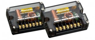
Crossovers Radiotehnika S-400M
We disassembled the speakers in the second part, looked at what they were made of and how they were designed. It was interesting to see the crossover - we will talk about it further.
Below are a few photos of crossovers that we managed to find on the Internet and my version of the factory crossover. As it turned out, “changes” were made from party to party. Apparently something with the supply of capacitors was not entirely smooth. Otherwise, how can we explain that they are from different manufacturers in all the photos?
The filters are built according to a classic parallel circuit, they are also called “ladder”, more on that below.
photo from the Internet. The first version of the components of the factory crossover Radiotehnika s-400m
As you can see, capacitors of the required capacity could not be found and they “molded” what was found. It even looks like Soviet-era capacitors. Or maybe this is them?
photo from the Internet. The second version of the components of the factory crossover Radiotehnika s-400m
It's the same story here - inconsistency. Well, the installation itself is no different in design from those Soviet s-90 speakers.
photo of my crossover. The third version of the components of the factory crossover Radiotehnika S-400M
This crossover that I got also has some problems with the capacitors. And still the same installation on plates from Soviet getinaks. Although at that time other manufacturers also used plywood, and why not.
Modern Radiotehnika S-400M is not far ahead in the design of its crossovers, unlike its comrades from the Middle Kingdom. The Chinese now have almost all crossovers assembled on foil PCB, tracks and regular soldering. Everything is beautiful. This is taking into account the fact that not all manufacturers make any crossovers according to calculations. It happens that the role of a crossover is played by a polar capacitor on the HF speaker.
Let's not argue - the quality of the Chinese crossover calculations is the same - sad, as is the correct location of the filter chokes.
Strange situation! For some reason, often, after finalizing only the crossovers, a sound appears that could have been calculated and obtained at the speaker design stage. But why doesn’t this happen in factories where professionals sit with the appropriate equipment and calculate all the filter parameters as they should be? Riddle question.
Greek writing
There is a Greek letter called “zeta”, written like this: ζ. A powerful letter, with its help you can do the unthinkable: using the same arsenal of frequency-dependent elements ( one inductance and one capacitance) to build crossovers with very different characteristics. To do this, we will insert a wonderful letter into the formulas already given. Like this:
L = ζ Rн/(2π Fo)
С = 1/ζ (2π Fo Rн).
Everything that came before assumed that ζ = 1. It is in this case that on a resistive load the parallel and series crossovers turn out to be twins. What if the Greek symbol is equal to something else? To this, parallel and series crossovers will react completely differently. If, say, we change ζ in the range from 0.5 to 2 and choose the values of the elements according to these values, the only thing that can happen to the parallel crossover will happen. When ζ > 1, the inductance will be greater than the calculated one, the low-pass filter cutoff frequency will decrease, and the high-pass filter cutoff frequency with a reduced (according to the formula) capacitance, on the contrary, will increase.
Figure 11. Parallel crossover at different values of ζ
The shapes of the frequency response of the filters (Fig. 11) will remain unchanged, and the quite expected “hole” will appear on the total frequency response. For ζ < 1, the opposite is true: the low-pass filter and high-pass filter curves will come closer together, resulting in a hump at the crossover frequency.
Figure 12. Series crossover at different values of ζ
Let's do the same with a series crossover (Fig. 12). How do you like this? The crossover frequency did not move; in a series crossover it is exhaustively determined by the value of the product of L and C according to the well-known formula of an oscillatory circuit:
Fo = 1/2 π(LC)1/2,
and it will remain unchanged when changed. But the quality factor of the circuit will change, as a result, the shape of the frequency response of the signal at HF and LF loads will change significantly. When ζ > 1 (high inductance, small capacitance), the circuit will be heavily damped, the frequency response of the links will have a slope even less than 6 dB/oct., the area of joint operation of the heads will become wide. However, as you might have already guessed, the total frequency response is again a horizontal straight line. At ζ < 1, the quality factor of the circuit will increase, and the slope of the frequency response of the crossover components will steadily increase. At ζ = 0.7 it will reach 9 dB/oct., and at ζ = 0.5 - all 12 dB/oct., the first-order filter becomes comparable to the second-order filter. As evidence: in Fig. 13 — frequency response of a second-order crossover with Butterworth filters and frequency response of a sequential crossover at the same frequency at ζ = 0.5.
Rice. 13. Comparison with 2nd order Butterworth crossover
Pay attention to the 3 dB high hump on the total frequency response of the second-order crossover; this is its property: either a deep dip at the crossover frequency (when the heads are connected in phase), or a low hump when the heads are connected out of phase.
Rice. 14. Comparison with 2nd order crossover of the Linkwitz-Riley type
The Linkwitz-Riley type filter does not have such a hump (Fig. 14); here, a comparable slope of the decline to a level of -15 - 20 dB was achieved even with a less decisive value of ζ. And again, to check, we replace the resistors with the equivalent of real heads (Fig. 15).
Rice. 15. Comparison with a 2nd order crossover on a real load
A collision with real life, as can be seen, did not benefit the carefully (but theoretically) calculated Butterworth, and based on equally theoretical calculations and even forgiving errors in determining, for example, the impedance of the heads, the serial filter worked from “no worse” to “ better,” depending on what you look at.
What gives a sequential filter such flexibility? Will it have to pay for something somewhere? In principle, yes, but some of the payback is inexpensive, while others may turn out not to be payback, but a bonus if applied to the place. The first payment: the lower ζ, that is, the higher the slope of the frequency response of the filters, the lower the impedance at the crossover input drops near the crossover frequency. The physical explanation for this is as follows: at small values of ζ, the series oscillatory circuit formed by the two crossover components turns out to be weakly damped by the load and begins to exhibit its characteristic consistent resonance. The scale of the problem is shown in Fig. 16, this is for an ideal, resistive load.
Rice. 16. Dependence of input resistance on ζ on an active load
If at ζ = 1 the impedance at the crossover input does not depend on frequency and is equal to the load resistance of the LF and HF section, then at an extremely (in practice) low value of ζ = 0.5, the impedance at the crossover frequency will be halved. For ζ > 1, it will increase, but this case is less interesting to us. The case of a real load is shown in Fig. 17.
Rice. 17. Dependence of input resistance on ζ on a real load
Second: the famous “And the phase?!.” In the ideal case (resistive load, ζ = 1), the phase shift between the LF and HF outputs is 90 degrees everywhere, just like a parallel filter, which is why it is purple in which polarity the heads are connected. For other values of ζ, the magnitude of the phase difference between the LF and HF signals will vary with frequency, in Fig. 18 shows how, at extreme values of the Greek letter.
Rice. 18. Phase difference between crossover outputs at different ζ
In the right hands, this is not a bug, but a feature; here the polarity of the switch begins to play a role, which means that an additional configuration tool appears (remember, in case anyone has forgotten, this is about a device consisting of two parts!). By the way, for those who are not satisfied with this, they can add a third one. The modified crossover circuit is shown in Fig. 19.
Rice. 19. Scheme of a modified crossover
Here the "crossbar" going to the connection point between the capacitor and the coil is replaced by a resistor RS. Why “S” - you’ll find out. It turned out (not without some surprise) that even with small values of this resistor, amounting to 5 - 15% of the head resistance (in our case 0.5 - 1.5 Ohms), the frequency response of the filter sections changes noticeably, reminiscent of the frequency response of the so-called “strange filters”, which have found application in second-order crossovers (Fig. 20).
Rice. 20. Frequency response of a crossover with a “strange” resistor
Rice. 21. Dependence of phase shift on RS value
The total frequency response of a series crossover, as usual, does not depend on the value of the “strange resistor” RS, but the phase shift does (Fig. 21), which means there is one more degree of freedom. However, whoever bothers adding an extra element to the elegant simplicity of a sequential crossover may try to take something away...
Comparative Features
That is, an active subwoofer is a passive subwoofer with a power amplifier, which is located inside or outside the housing. And if in the case of an active subwoofer the developer has already taken care of us, then for a passive subwoofer we will have to buy an amplifier separately. At the same time, sometimes there are kits on sale that consist of a passive subwoofer, a separate power amplifier selected by the manufacturer, as well as a set of wires for connection.
For both active and passive subwoofers (a separate subwoofer speaker can also be called a passive subwoofer, except that it comes without a housing), cabinet designs are used - a closed box (a completely sealed volume for the speaker) and a bass reflex box (the box has an outlet port or slot). Also, passive subwoofers often use a Bandpass box design (the box is divided into two volumes and provides a more complex configuration of drop-off ports), which is very rarely used in active subwoofers. At the same time, active subwoofers often have compact designs (the smallest design volume is achieved), which, of course, are not used in passive subwoofers.
Installation of both passive and active subwoofers (not taking into account the compact design) is carried out in the trunk of a car, regardless of the body. Compact active subwoofers are usually installed on the back of the rear seats or under the car seat.
And now about the most important thing - the advantages and disadvantages of active and passive subwoofers. Let's consider three main arguments that are of greater interest to car owners - cost, compactness of installation and possible end result.
Active or passive / Cost comparison of equipment and installation
As a rule, the cost of active subwoofers is slightly higher than passive ones, due to the presence of a built-in power amplifier. But due to the fact that for a passive subwoofer it is necessary to purchase a separate power amplifier and also install it, the cost of equipment and installation of a passive subwoofer is higher than that of an active subwoofer.
Active or passive / Installation compactness comparison
Manufacturers are trying to make the housing for an active subwoofer as compact as possible, even taking into account the space for the amplifier. This is not to mention active subwoofers in a compact design, which do not take up any significant amount of free space at all. That is, passive subwoofers take up more free space (although not always), especially since some space is also required for installing a power amplifier.
Active or passive / Comparison of the final result
For the most part, an active subwoofer is used as an addition to the main sound stage. That is, it introduces some low-frequency component, but there is no noticeable accentuation on it. At the same time, the passive system allows you to achieve the necessary characteristics from the sound of the subwoofer - quality, power, bass depth. And although there are very good active systems, they are all very expensive, which negates the above advantages of such subwoofers.
What is a subwoofer for?
“Sub” is a design responsible for the reproduction of low-frequency bass, which has high power and high pressure. As a rule, a subwoofer is installed when a full set of speakers is already installed.
A subwoofer differs from a regular speaker in some characteristics. In addition to external differences, one can note the diameter of the diffuser; here it is larger. The subwoofer is designed to play music in the range of 10–150 Hz.
A high-quality audio system can reproduce a wide range of frequencies perceived by humans. But it is impossible to achieve such sound using only speakers. Therefore, a subwoofer is installed when the sound of standard speakers becomes insufficient and you want low-frequency bass. It is worth understanding that a subwoofer is an additional part to the speaker system installed in the car, and without them its installation is pointless.
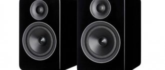
Single speaker models
Single speaker speakers are very common.
To assemble the model, you will first have to deal with the body. Plywood is often used for this purpose. At the end of the work it will have to be sheathed. However, the first step is to make the side posts. For this purpose you will have to use a jigsaw. The speaker for the column can be selected with low power. The inside of the plywood is necessarily stitched with vibration-proof tape. After fixing the speaker, the seal is fixed. Glue is used for this purpose. Next, all that remains is to attach the diffuser. Some people make a separate shelf for it and fix it with stacking screws. To connect the speaker to the plug, a terminal block is installed. How to turn on speakers? For this purpose, a cable is used from the terminal block, which should lead to a power source.
Low Frequency Speaker Systems
Design features of professional subwoofers or what parameters to follow when choosing a subwoofer
From this article you can find out in which sets of audio equipment you need to use subwoofers, get acquainted with the existing types of subwoofers and the advantages of their use. In which sound sets should subwoofers be used? In sound sets where convincing transmission of low frequencies and enhanced emotional impact are important, subwoofers are necessarily used. Examples of such sound kits include: sound equipment for discos, sound for watching films with special effects and, of course, concert equipment. We also recommend using subwoofers in sound equipment sets for retail spaces and restaurants to enhance the emotional impact on visitors. The subwoofer saturates the sound with low frequencies, making the sound more full and comfortable.
Which head units to choose?
by installation size: 1 DIN and 2 DIN - these are international size standards adopted by manufacturers since 1984.
— 1 DIN — size 178×50 mm; — 2 DIN — size 178×100 mm. There is also an intermediate 1.5 DIN format with dimensions of 178x75 mm. This standard is not widely used. As for the depth of radio tape recorders, here manufacturers are limited only by common sense. However, the average depth of radio tape recorders is 160 mm. Most car manufacturers provide for the installation of a radio of one format in their cars, however, models with a socket for a 2DIN radio make it possible to install a 1DIN radio - to do this, just install an adapter frame. Not all manufacturers have switched to the DIN standard, and continue to install standard radios on their cars with dimensions not provided for by the standard. Therefore, when replacing a non-standard standard radio with a 1DIN or 2DIN radio, it is necessary to use an adapter frame.
For 2 DIN car radios, you can choose either a simple sectoral display or a multimedia one with a touch screen. Once again, the sound quality will be influenced by the element base - the parts from which the radio is assembled. Let's say: 1Din - in high-quality performance it can sound an order of magnitude better than the Chinese 2 DIN multimedia with navigation, cameras, video recorder and other “goodies”.
If the question is about sound quality and a rear view camera or several cameras, navigation - then your choice is definitely multimedia stations that can do a lot in addition to reproducing high-quality sound. By the way, they can also be 1 DIN in size (the screen can “move in and out” inside the car radio).
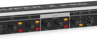
Amplifiers -
It is impossible to imagine a modern high-quality car audio system without an amplifier, and there are several reasons for this. It improves the sound quality of music even when listening at low volumes, due to the fact that its level of distortion is much lower than that of the amplifier built into the radio. Without an amplifier it is impossible to achieve natural sound in a car. Car amplifiers are equipped with a large number of built-in filters and controls that allow you to fine-tune your multi-band system. Such systems also require replacing standard audio wiring with higher quality, specially designed (with low resistance in a certain range of transmitted frequencies).
How to choose a subwoofer for your car: active or passive?
One of the main divisions of subwoofers into groups involves focusing on the presence or absence of an amplifier. According to this criterion, the following are distinguished:
| Type of subwoofer | Built-in amplifier | Advantages | Flaws |
| Active | + |
|
|
| Passive | — |
| the need to independently select the main elements of the system - subwoofer, head unit and amplifier |
The most popular is the active subwoofer. It is well suited for rhythmic and dance music, leaving the user the right to freely customize the sound. It is this type of sub that is recommended to be purchased by beginners and those who do not want to spend a lot of time searching for individual components.
Passive models should be chosen either for an existing free amplifier, or for music lovers who want to get the most spacious and high-quality sound. But you should keep in mind that the desired result can only be achieved by correctly assembling the system, and this may require the help of professionals.
How to do it yourself
Making a crossover yourself is difficult. Car owners are often faced with the fact that even an expensive two-way front speaker system does not have this device. To create an element at home, you will need:
- silicone sealant;
- convenient soldering iron;
- heat-shrink tubing;
- good glue;
- foil fiberglass;
- inductance measuring device;
- ferric chloride.
In some cases, you need to prepare the wires to connect all the parts. A homemade device is made as follows:
- wind copper wire 1 mm thick onto the inductor;
- they use a ferrite core for the base, which reduces the weight of the structure and its dimensions;
- measure inductance using a device;
- make a board from foil fiberglass, making holes in it for wires and various parts;
- pickle the board in ferric chloride;
- attach capacitors and an inductor to the board using glue;
- connect the speaker wires using a soldering iron with a thin tip and observing polarity during connection;
- The finished product is covered with a heat-shrinkable tube, the edges of which are covered with a layer of sealant to increase reliability.
If you follow the sequence of actions, you can assemble the crossover yourself with minimal costs for purchasing the necessary materials and tools.
What is a subwoofer and how is it different from a regular speaker?
A subwoofer is a specially designed device that solves one simple problem: reproducing low frequencies. The human ear begins to perceive vibrations from 20 Hz. For particularly sensitive individuals, this figure may be lower.
The problem with conventional speakers is that they are technically incapable of reproducing low frequencies well. Despite the fact that the parameters indicated in the documentation state that the operating range is, for example, 20-45000 Hz, in practice two-way acoustics sound somewhat flat. This happens for the following reasons:
- No device is capable of showing the same efficiency over the entire range of possible frequencies. At the edges there is definitely a failure in the frequency response. Most modern devices are not capable of accurately reproducing frequencies up to 400 Hz.
- The diameter of the speakers of two-way speakers is insufficient for sudden pressure surges. This parameter creates a juicy and thick bass.
- When operating a wideband speaker, the frequency range is sharply narrowed. The signal is averaged due to the inertia of the membrane and the coil’s response is not fast enough. As a result, achieving rich bass is simply unrealistic.
The characteristics of a subwoofer clearly show how it differs from a speaker. Firstly, the device’s operating frequency range is forcibly cut off. For the average subwoofer model it is in the range of 40-200 Hz. Secondly, the product is equipped with a really large sound emitter. The diameter of the membrane can be 30-50 cm for models for home use and up to a meter for stage subwoofers.