What is crossover slope?
I continue to produce educational material))) Today I will try to tell and show you in an accessible language what filters are and how they work.
Each audio system component must reproduce its own frequency range. The subwoofer should not sing, and the front should not play bass at 30 Hz. By cutting off unnecessary frequencies from the speakers, we will make their life easier, increase the maximum volume of the system and improve the overall sound quality.
Filters come in two types: - high pass filter (HPF) - low pass filter (LPF) The first one passes high frequencies, suppressing frequencies BELOW the cutoff frequency, the second one, accordingly, passes low frequencies and suppresses frequencies ABOVE the cutoff frequency. The subsonic filter in subwoofer amplifiers is essentially a high-pass filter.
It seems that everything is simple and clear, it cuts the bottom, there it cuts the top, BUT! no filter cuts off the signal sharply! Your subwoofer, cut at, say, 63 Hz, will play 100 and even 200 Hz, but at a much lower volume.
Here we remember the order of the filters - it is this that determines the steepness with which the signal will attenuate relative to the cutoff frequency. The order can be 1st (6 dB/octave), 2nd (12 dB/octave), 3rd (18 dB/octave), 4th (24 dB/octave), etc. What is db/oct you ask!? - this is the number of decibels, how much quieter the signal will become after an octave. And for how long? - 6 dB is 4 times quieter, 12 dB is 16 times quieter, 18 dB is 64 times quieter, 24 dB is 256 times quieter. What is an octave!? — well, in general, this is a frequency range that is twice as high or below the cutoff frequency))) Didn’t you understand anything?))) I spent the whole night drawing pictures especially for this))) Let’s take a look!
The blue graph is a subwoofer cut to 63 Hz in the second order. This means that after an octave (63x2=125 Hz) the signal will be 12 dB quieter, i.e. 16 times. The green graph is a subwoofer cut to 63 Hz in the fourth order. The attenuation slope is significantly higher, which means a drop in sound pressure to 125 Hz by 24 dB, i.e. the subwoofer will reproduce 125 Hz, but 256 times quieter! The red graph is a midwoofer cut to 125 Hz in the second order. After an octave (125/2=63 Hz) its volume will drop by 12 dB. The yellow graph is a midwoofer cut at 80 Hz in the fourth order. Again, the speaker will play at 20 Hz, but already at 40 Hz (80/2) its volume will be negligible.
I think everything turned out to be extremely simple and clear. It’s very convenient to draw such pictures on paper to quickly figure out how, for example, a subwoofer and a midwoofer will be coordinated in your system. Good luck with the setup!
Source
What is a frequency filter?
A frequency filter is a device (device) designed to pass useful signal frequencies and limit useless ones.
The frequency filter is commonly used in both analog and digital musical instruments (such as synthesizers).
In music production, frequency filters are used to automate the cutoff frequency of the filter. Additionally, cutoff frequency and resonance can be used as a parameter for modulation in synthesis. In this case, envelopes or low-frequency wave generators (LFOs) are used.
Let's look at the basic parameters of a frequency filter.
Filter type
This parameter determines the directionality of the filter (its target).
Low Pass (LP) or High Cut (HC) – low-pass filter or high-pass filter. This type of filter allows all frequencies below a specified value to pass through (or cuts all frequencies above a specified value).
High Pass (HP) or Low Cut (LC) - high-pass filter or low-pass filter. Passes all frequencies above the specified one (or cuts all frequencies below the specified one).
Band Pass (BP) – bandpass filter. Passes frequencies of a certain band.
Notch – notch or band-stop filter. Cuts out frequencies of a certain band.
Low Shelf – low-frequency shelf (or shelf) filter. Boosts or attenuates frequencies below the specified value.
High Shelf – high-frequency shelf (or shelf) filter. Boosts or attenuates frequencies above the specified value.
Bell or Peaking – bell-shaped or peak filter. This type of filter is used in equalizers to boost or cut a selected frequency range.
There are other specific types of filters, for example:
Comb – comb filter. The frequency response of this type of filter consists of a series of peaks that resemble a comb.
Tilt Shelf is a combined shelf filter. Simultaneously enhances high frequencies above the specified value and attenuates low frequencies below the specified value, or vice versa.
Cutoff frequency (Cutoff or Freq)
This parameter sets the operating frequency of the filter. For example, for a Low Pass filter, this is the frequency above which the entire useful signal will be suppressed (cut), and for a Bell filter, this is the center frequency of amplification or attenuation.
Bell filter cutoff frequency
Low Pass Filter Cutoff Frequency
Quality factor, resonance or bandwidth (Q or Res)
This parameter sets the bandwidth of the affected frequencies relative to the center frequency (cutoff frequency) or the resonance at the cutoff frequency. For the Bell filter type, this is the bandwidth of the affected frequencies (smoothness of amplification or attenuation of frequencies), and for cut-off and shelf filters, this is the resonance at the point of cutoff of frequencies or at the point of amplification or attenuation of frequencies.
Filter resonance
Filter Bandwidth
Cut steepness
This parameter characterizes the smoothness of the frequency cutoff, mainly for low-cut filters. It shows how steep this cut will be.
Filter slope is measured in dB per octave.
Filters can have the following slope: 6; 12; 24; 36; 48; 72; 96 dB/oct.
Cutoff slope - 12 dB per octave
Cutoff slope - 96 dB per octave
Basically, the filter block of electronic (virtual) musical instruments uses a cutoff slope from 6 to 48 dB per octave.
Gain Level
This parameter is used in shelf and peak filters. It shows the level of boost or cut in a frequency band in dB.
6.78 dB bandwidth gain
At the end of the article, I would like to draw your attention to the importance of understanding the operation of a frequency filter, since it is impossible to do without this “tool” when creating electronic music. After all, the frequency filter is used both in synthesis (subtractive synthesis) and in mixing. This includes filtering, equalization, and automation.
Digital signal processing
DIGITAL SIGNAL PROCESSING
Digital signals processing. Digital recursive frequency filters.
Topic 10. RECURSIVE FREQUENCY DIGITAL FILTERS
Blessed be the Lord, who made everything necessary easy, and everything difficult unnecessary.
Grigory Skovoroda. Ukrainian philosopher, XIII century.
Recursive filters are needed when processing data. However, they are difficult to develop. It follows that the Almighty did not create filters, and is not responsible for the consequences of their use.
Father Dionysius, in the world V. Lebedev. Geophysicist of the Ural school, XX century.
Content
Introduction.
1. Low-pass Butterworth filter. Transmission function. The steepness of the cut. Filter order. Laplace transform. Bilinear transformation.
2. High-pass Butterworth filter. Synthesis of filters using the frequency conversion method.
3. Butterworth bandpass filter. Spectrum splitting. Bandpass filter on the s-plane. Transmission function.
4. Chebyshev filters. Filters of the first kind. Filters of the second kind.
5. Additional information.
Introduction
The process of designing a recursive frequency filter usually consists of specifying the required filter transfer characteristic in the frequency domain and approximating it to a certain accuracy with some continuous transfer function, followed by a z-transform to transfer to the z-domain. The first two operations are well established in the theory of analog signal filtering, which makes it possible to use a large reference material on analog filters for designing digital filters. The last operation is specific to digital filters.
To algebraically transform a continuous transfer function into a polynomial in z, a bilinear transformation is used, known in the theory of complex variables as a fractional linear transformation.
10.1. Low-pass Butterworth filter /12.24/.
Rice. 10.1.1. Frequency response of the Butterworth filter. |
Transmission function.
The smooth form of the amplitude-frequency response of the Butterworth filter (Fig. 10.1.1) is specified by the square of the transfer function of the form:
|H(W)|2 = H(W)H*(W) = 1/(1+W2N).
where W = w/wc is the normalized frequency, wc is the cutoff frequency of the filter’s frequency response, at which |H(w)|2 = 1/2 (respectively, H(w) = 0.707, or 3 dB), N is the filter order, which determines slope of the frequency response cutoff. Function |H(W)|2 – represents the energy spectrum of the signal (spectral power density) and has no phase characteristic, i.e. it is an even real one, formed by the product of two complex conjugate functions H(W) and H*(W), As W → 0, the filter transmission coefficient tends to 1. Considering that the calculation results will relate to digital filters and during the z-transform with the transition to the main frequency range, frequency distortion will occur, before the calculations begin, the actual values of the specified frequency characteristics (the values of wc, wp and ws) should be converted into values of deformed frequencies according to the expression:
wd = (2/Dt) tg(wDt/2), — p/Dt
The steepness of the cut.
The slope of the filter's frequency response during the transition from the transmission region to the suppression region can be characterized by the filter cutoff coefficient K in decibels per octave:
K = 20 log|H(w2)/H(w1)|, (10.1.2)
where w1 and w2 are frequencies with an interval of one octave, i.e. w2 = 2w1.
The duration of the filter's impulse response within its significant part also depends on the slope of the cutoff: the greater the steepness, the longer the duration of the filter's impulse response.
Filter order.
Taking w1=Wc, w2=Ws and substituting the values of H(W) with the given data into (10.1.2), we obtain an approximate expression for determining the filter order for a given value of K:
N = K/6. (10.1.6′)
Thus, to guarantee a signal attenuation in the suppression band by 100 times (40 decibels), the filter order is N = 7. On average, when N changes by one, the signal suppression coefficient changes by 6 decibels.
The initial requirements for the filter transfer function are usually specified in the form of values of wp, ws and unevenness (ripple) coefficients Ap and As (see Fig. 10.1.1). To determine the cutoff frequency wc at the level of 0.707 and the filter order, we introduce the parameter d, related to the coefficient Ap by the following relation:
(1-Ar)2 = 1/(1+d2).
d = [1/(1-Ap)]= Ap/(1-Ap). (10.1.3)
To take into account the deformation of the frequency scale in the process of bilinear transformation when subsequently transitioning to polynomials in Z, we calculate the deformed frequencies wdp and wds using the formulas:
wdp= 2 tg(wpDt/2)/Dt, (10.1.4)
wds= 2 tg(wsDt/2)/Dt.
At the normalized frequency W = w/wdc, where wdc is also the deformed frequency, the following equalities are satisfied at the boundaries of the transition zone:
1/(1+d2) = 1/[1+(wdp/wdc)2N], (10.1.5)
As2 = 1/[1+(wds/wdc)2N].
From here:
d2 = (wdp/wdc)2N, 1/As2 - 1 = (wds/wdc)2N.
Solving these two equations together, we find:
N = ln / arcch(ws/wp). (10.4.5)
Further calculations are identical to the calculations of Butterworth filters, as well as the frequency conversions of low-pass filters to high-pass filters and filters.
Filters of the second kind.
For Chebyshev filters of the second type, with a smooth transfer characteristic in the transmission zone and equal-wave ripples in the suppression zone, the function is used:
|H(W)|2 = 1/[1+d2(TN2(Ws)/TN2(Ws/W))], (10.4.6)
where W = w/wp, Ws = ws/wp. The condition for setting parameter d remains unchanged. At the boundary of the suppression band at w = ws: 1+d2TN2(ws/wp) = 1/As2, from where the value of N is also determined similarly to a filter of the first kind. The further procedure for calculating Chebyshev filters of the second kind does not differ from filters of the first kind.
Coursework 17-07.
Development of a program for calculating a universal frequency digital Chebyshev filter (low-frequency, high-frequency, bandpass) and filtering digital signals.
10.5. Additional information.
When using RCF, the issue of the duration of the actual attenuation of the transient process is often overlooked. Meanwhile, to effectively launch the RCF, a stream of input data xn and a set of initial values уn are required. If the initial values of уn are unknown and assumed to be zero, the initial transient switching process is inevitable. At the same time, there is a clear tendency - the greater the steepness of the filter, the longer the transient process takes to decay. Therefore, RCF is used mainly when processing fairly extensive arrays. When processing short arrays, the length of which is commensurate with the duration of the RCF transition process, a preliminary selection of initial values уn is necessary. As a rule, it is carried out purely empirically, using various sets of initial data.
The second factor to consider is phase shift. If, when processing data, the phase shift of the input signals is unacceptable, then you should use either an additional compensating filter that restores the phase of the processed signals, or use sequential double filtering with the same type of recursive filter with forward and backward passage of the processed data.
literature
12. Kanasevich of time sequences in geophysics. - M.: Nedra, 1985. - 300 p.
18. Nikitin basics of geophysical information processing: Textbook for universities. - M.: Nedra, 1986. - 342 p.
24. Hamming filters. – M.: Nedra, 1987. – 221 p.
Author's main website ¨ Lectures on DSP ¨ Workshop
About noticed typos, errors and suggestions for additions: *****@***ru.
Copyright © 2008 Davydov A. V.
Let's remember the school physics course. The main property of an inductor is that it resists rapid changes in the current flowing through it. In other words, at low frequencies its resistance is small, but with increasing frequency it increases noticeably. If you connect it in series with a speaker, it will pass low frequencies through it, but attenuate high frequencies, and we get a real low-pass filter. But a capacitor has exactly the opposite properties - it does not pass direct current through itself at all, but it can pass alternating current. Moreover, the higher the frequency of the signal, the less resistance it will provide to it. So if we connect a capacitor in series with the tweeter, we will get a high-pass filter that attenuates low frequencies, but easily passes high ones.
Each of these filters will consist of one element and they will be called first-order filters
. They are easy to calculate because they contain only one element each - a coil or a capacitor. If we want to make filters with a certain cutoff frequency Fc (it is determined by the level of –3 dB), then we will need to select a coil and capacitor with the following parameters (inductance in mH, capacitance in µF):
where Z is the impedances of the speakers (ohms) that we are going to connect to the filters. Often in calculations, nominal impedances are substituted for Z. In general, this is really a way to estimate as a first approximation the approximate order of magnitude of a coil or capacitor we will need, but nothing more. If an accurate calculation of parameters is required, then for this you need to know the Z-characteristic of the speakers itself, and substitute not the nominal values of the impedances into the formula, but the values at a specific frequency Fc.
The disadvantage of first-order filters is their low cutoff slope, about 6 dB/octave. In other words, they do not “diligently” filter the signal, which means that with such filters a wide range of frequencies will be reproduced by both the tweeter and the midbass speaker at the same time.
This is bad due to the fact that the speakers, as a rule, are spaced a fairly decent distance from each other in a car. As a result, what will reach the ears is not what they emit, but some result of addition, interference. Well, the fact that different speakers cannot reproduce the same signal in exactly the same way only makes the situation worse.
To get rid of this drawback and reduce the range of joint operation of the speakers, filters of higher orders are used. For example, if we add one more element to the first-order filters, we will get a second-order filter
.
Such a filter gives a steeper drop in frequency response outside the passband, hence the narrower band of joint operation.
With further addition of elements using the same principle, filters of the third, fourth and even higher orders can be obtained. They will do an even better job of filtering.
And everything would be fine, but any filters have one unpleasant feature - they shift the signal in phase and delay it. At first glance, there is nothing wrong with this, because, for example, sound processors also delay the signal. But the fact is that processors delay the signal “entirely,” and filters have different delays at different frequencies. What happens if we delay some frequencies more than others in a broadband music signal? The signal shape, of course, will be distorted. Such distortions are called phase distortions. And the higher the order of the filters, the greater this phase unevenness. I am in no way advocating that high-order filters should be abandoned, but it is better to treat them with caution.
Column separation filters
In multi-band acoustics, separate speakers are used to reproduce different frequency ranges. But how does this signal distribution come about? A special circuit is responsible for it - a separation filter (crossover), which can be considered the brain of such Hi-Fi acoustics.
Two-way acoustics Triangle Borea BR03 cannot do without a crossover filter
“A crossover is a device in an acoustic system that creates the necessary operating frequency ranges for the correct operation of the speakers.”
In other words, the crossover determines what frequencies (frequency range) each speaker in the speaker will produce. But that is not all. The crossover filter is actually an intermediary between the amplifier and the speakers. If a speaker does not have a crossover, its tweeter, connected directly to the amplifier, will most likely simply burn out. In any case, a speaker in which all speakers receive the same signal from the amplifier will sound with great distortion.
Frequency sharing rules
Correctly designing a crossover in speakers requires not only engineering talent, but also a budget, which will be included in the total cost of the future model. Let's briefly define some basic terminology that will be helpful in understanding how a crossover works. For example, in a two-way (equipped with a woofer and tweeter) acoustics, a crossover consisting of two filters should be used. This is a high-pass filter that allows signals in this range to pass through, but blocks low frequencies. And a low-pass filter that lets the bass through and blocks the highs.
Triangle tweeter
So, let's return to our tweeter, which simply physically cannot reproduce low frequencies. In order for this speaker to work correctly, the signal is fed to it through a high-pass filter. On the contrary, for the bass driver you will need a low-pass filter. As a result, both speakers will sound only at their “own” frequencies, which they were designed to reproduce.
Filter slope
The filter has another important characteristic - the slope of the cut. This is where things get a little more complicated. It shows how many times the filter attenuates the signal and is measured in dB/octave. The degree of steepness of the filter cutoff determines its order. Thus, a 1st order filter has a cutoff slope of 6 dB/octave and attenuates the signal by 4 times. The highest (of those used in crossovers) cutoff slope of 24 dB/octave has a fourth-order filter. A filter with such a slope will attenuate a signal outside its pass frequency by 256 times. The higher the order of the filter, the more complex it is to implement and the more electronic components are required to create it. Some manufacturers install simple second-order filters in their speakers, claiming that this is better for the sound: a simpler circuit, which means less distortion. Moreover, some acoustics do not have a filter for the woofer at all. Unfortunately, in practice this can cause poor sound from the speakers.
Triangle Antal 40th Anniversary woofer
Simple or complex filters?
If the woofer does not have a filter in the column, then it will work across the entire frequency range. In some cases, the range of operating frequencies of a woofer may be limited “from above” due to its design. However, this requires fine-tuning the parameters of the speaker (that is, in fact, making it to order), which is theoretically feasible, but quite expensive. In the case of a conventional serial bass speaker, the result of the absence of a low-pass filter in the crossover will be the appearance of overtones at high frequencies. And their visibility will increase as the overall sound volume increases. This is especially noticeable with speakers with rigid cones, which can begin to "sound" at high frequencies even with a low-pass filter.
Simple separation filter, low cost
First-order filters do not cope well with low frequencies, which can cause problems with the tweeter. Using them may increase the load on the tweeter. And if you turn on the music too loudly, the tweeter will simply burn out. In addition, with such a crossover, the sound of the speaker at high volumes may become less detailed and transparent. We can say that a simple crossover will almost always produce more distortion in the sound than a correctly calculated complex one. Of course, if low quality components are used to make both crossover filters, a simple circuit containing fewer components may well have an advantage. But only in this case.
High quality Triangle separation filter
In principle, the quality of a separation filter in a column can be determined simply by its appearance. It is a pity that many of us are deprived of this opportunity. If the crossover is small and consists of a small number of parts, most likely they simply saved money on it when manufacturing the acoustics. Of course, we are not talking about High End class models, the design of which can be quite exotic.
What is the cutoff frequency of a subwoofer and how to set it correctly
The configuration of modern audio amplification equipment that creates surround sound assumes a functional separation of channels. This audio system includes front and rear speakers, a center channel and a subwoofer.
The latter serves to create additional sound effects in the lower frequency range from 20 to 180 Hertz. This additional device is mainly used when watching video programs and films that contain scenes of explosions, space rocket launches and similar situations, during the sound of which you need to shake the air quite intensively.
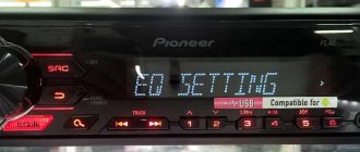
As a rule, subwoofers are designed according to the active principle, that is, they have their own built-in amplifier, power supply and controls. The controls and settings include two main knobs: Level and Crossover Frequency. The purpose of the level knob is quite clear; it is to regulate the intensity of the sound signal. But why the second setting is needed is not clear to everyone.
Unlike full-range speakers, a subwoofer has a limited frequency range at the upper edge. In turn, the bass is conventionally divided into deep - up to 40 Hz, mid - up to 80 Hz, and high - up to 160 Hz. The depth of the achieved acoustic effect depends on what cutoff frequency is set. In some cases, participating in the high bass spectrum creates a softer sound, such as when listening to music or watching movies that are not loaded with special effects. If a more severe impact on the viewer’s nervous system is required, for example, when seeing collapsing buildings or exploding planets, then the cutoff frequency of the subwoofer can be shifted closer to the infra-range.
Technically, implementing upper frequency limitation is not a difficult task. From the physics course it is known that capacitors have a filtering property in relation to low frequencies, and inductances have a filtering property in relation to high frequencies. Thus, the simplest LC filter can quite effectively isolate the desired portion of the range, while reducing the signal level of the unwanted spectrum. To “prevent” high and mid frequencies from entering the subwoofer input, it is enough to connect a small capacitor of several picofarads in parallel to the input terminals. But such a primitive filter will give too smooth a decrease in the amplitude-frequency response, so in practice their design is somewhat more complicated.
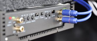
In addition, the cutoff frequency is also ensured by filtering the output signal going to a powerful loudspeaker. To do this, inside the case next to the speaker there is another board with capacitors and inductors.
The cutoff frequency of LPFs (low pass filters) should ideally be adjustable, although inexpensive systems may not have this feature.
Properly setting up a subwoofer in relation to the other acoustic components of a home theater system requires patience and care. A control that is considered good is one in which the bass emitted by the front and rear speakers is complemented by the infra-low frequencies transmitted by them, rather than “arguing” among themselves as to who is stronger. The principle “the louder the better” does not work here.
Thus, the cutoff frequency is an important setting to ensure that the entire system sounds correctly and consistently.