3-way speaker (6GD-2 + 4GD-4 + 6GD-13). Acoustic system with increased efficiency
The sound pressure level developed by the speaker is determined by its sensitivity (efficiency) and supplied electrical power:
L = S + 20 lg · √P = S + 10 lg · Р , where
The bulk of domestic speakers have a sensitivity of about 86 dB√W (Amfiton 50AC-022, 35AC-018, 25AC-027, S-90, etc.) and only a few - S-90B, S-90D, S-100V, Cleaver 75AC -001 – 89-91 dB√W. With a higher (3-5 dB) sensitivity, 2-3 times less power is required to create the same sound pressure level, or the pressure level will be the same dB higher with equal power supplied to the speakers.
For example, to obtain a sound pressure level of 100 dB, 25 W must be supplied to 35AC-018, 12.5 W to S-90B, and only 8 W of electrical power to 75AC-001.
When designing speakers, it is of interest to use loudspeaker heads with high efficiency and sensitivity - 90 dB√W or more, such as 6GD-2, 10GDSh-1, 4A-32, 100GDN-3, etc.
The 6GD-2 head, and before it the 5GD-3 head, developed at the Riga Radio Plant (RRZ) more than 35 years ago, were used in the Symphony tube radio speakers. Many sound lovers note their pleasant sound and high “return”, but in the region of the lowest frequencies there is a clear decline.
The averaged frequency response of several Symphony speakers in the frequency range below 250 Hz is shown in Fig. 1 (curve 1). The measurements were carried out in the “near field” using an MKE-3 microphone with an uneven frequency response of ±0.5 dB in the frequency range 20-700 Hz. The graph shows that the frequency response of the speakers has a steep decline below 70 Hz, with minima at a frequency of 100 Hz (about 4-5 dB) and in the frequency range 180-250 Hz (about 3-4 dB).
An analysis of the design of the Symphony speaker system showed that a separate volume in the lower part of the cabinet with two holes with diameters of 23 and 31 mm in the horizontal partition, often mistakenly mistaken for the design of a phase inverter (PI), is in fact a low-Q two-frequency notch acoustic filter (Helmholtz resonators) , tuned to frequencies of 50 and 100 Hz to partially suppress the 1st and 2nd harmonics of the mains frequency of the tube amplifier circuit. In addition, this design eliminates the inevitable “hump” in the frequency response in the region of 60-80 Hz, which is formed due to the high (more than one) quality factor of the “amplifier-speaker” complex, caused by the low flexibility of the air in the speaker volume (V = 60 l), far from zero output impedance of the PA, as well as the active resistance of the connecting wires of the speakers and the low-pass filter connected in series with the head.
The decrease in frequency response in the region of 180-250 Hz is caused by a design feature of the 6GD-2. Due to the insufficient rigidity of the diffusers, the “piston” operating range of the heads (the diffuser oscillates as a single whole) extends only to frequencies of 140-160 Hz, and then the region of broken frequency response begins, typical for this type of heads.
The frequency response of a closed-type speaker in the “piston” range is horizontal at frequencies above the resonant one (fp), below fp it has a decline of about 12 dB/oct, and at the most resonant frequency it has a transmission coefficient (relative to the level of the horizontal section) numerically equal to the total quality factor of the speaker – Qp on fp. When Qp 1, the frequency response has a “hump” at fp. If the Qts value is close to unity and lies in the range of 0.95 – 1.0, then a slight increase in the frequency response (0.5-1.3 dB) is observed in the frequency range above fp. The above applies to the case when there is no sound-absorbing material (SAM) inside the speaker.
To design an improved acoustic design, measurements were taken of the main electroacoustic parameters of seven copies of 6GD-2: resonant frequency fp, total quality factor Qp, flexibility of the moving system C and equivalent volume Ve. The obtained values are shown in Table 1 , column “V=∞”.
The volumes of the phase inverters were determined to obtain the most “smooth” frequency response, which are shown in the “FI” column of Table 1 .
ACOUSTICS HAVE THE FINAL WORD
And now, having finally become the owner of a high-quality amplifier (see “M-K” No. 7, 8 for 1975), you happily decide: “Now the matter is small: the only thing missing is the sound speakers.”
Without further delay, you go to the nearest radio store and, having discovered a wide variety of sound-reproducing products there, you involuntarily find yourself in a difficult situation. But what, exactly, should you choose? The best adviser for a specialist is the technical characteristics of the device. But sometimes they don’t say much to an amateur. And yet, let’s try to figure out what high-quality sound speakers should be like.
Let's start in order. Let's find out what minimum frequency band they reproduce. Experts say: from 30-45 to 15,000-18,000 Hz. And the wider this range, the larger the base the speakers can be classified as high-quality. But this is not enough. It is also important to know what the unevenness of the frequency response is in the frequency range. Agree, it’s unpleasant if some orchestra instrument sounds incredibly loud. It drowns out other instruments, disrupting the aesthetic perception of the sound picture as a whole. Or, conversely, you do not hear the sounds characteristic of certain instruments, such as violins, which add lightness and intimacy to the piece being performed. This indicates that the system reproduces various frequencies unevenly. The musicians limited the permissible unevenness to ±4 dB. This magnitude is practically not felt even by discerning listeners.
Ideal speakers reproduce frequencies from 20 to 20,000 Hz with an unevenness at the edges of the range of ± 6 dB. Speakers with such characteristics are expensive, and the difference in sound quality between them and speakers with a bandwidth of 40-18,000 Hz ± 4 dB is almost imperceptible. In addition, the latter are usually 3-4 times cheaper than the former.
Another important characteristic of a speaker is the coefficient of nonlinear distortion in sound pressure. It is clear that there are no two opinions in assessing this characteristic: the less distortion, the better. But what is the acceptable limit? Not higher than 3% in the entire range of reproduced frequencies.
Rice. 1. Column design:
1 — back wall with holes, 2 — body, 3 — front panel.
How much controversy flares up when it comes to the electrical power of speakers! How often among stereophonic lovers one can hear notes of disdain towards low-power speakers. And how much dignity there is in the voice of owners of forty-, fifty- or sixty-watt speakers!
Do the latter have a reason for this? Yes and no. After all, the capabilities of speakers are judged practically by the amount of sound pressure they develop, or, as they say, sound volume. The latter, naturally, depends on the electrical power supplied to the column. But there is one more indicator, without which it is impossible to determine in advance which speaker sounds louder. This refers to the efficiency of loudspeakers, or, as they say now, heads. A ten-watt speaker equipped with 15% efficiency heads will naturally sound louder than a twenty-watt speaker with 5% efficiency heads.
Still, preference should be given to high-power speakers. They are more reliable, introduce less distortion and, very importantly, have a greater dynamic range: they sound more natural.
And what to answer to those who ask: “Which speakers are better: four-ohm or eight-ohm?” If such a question had been asked in the fifties, it would have raised eyebrows. In tube ULFs, the power supplied to the load does not depend on the resistance of the speakers (of course, if the output transformer has taps for connecting loads of various sizes).
Transistor bass amplifiers are another matter. Their output power depends on the size of the load: the lower its resistance, the higher the power delivered to the load. Therefore, all other things being equal, low-impedance speakers will develop higher sound pressure than high-impedance speakers.
Are the column parameters listed only? No. But others are of secondary importance. For example, the ratio of electrical power to the volume or weight of the speaker, directivity characteristics, etc.
Many people are concerned about which speakers are better: acoustic or compression? Objectively, there is no difference in sound quality between both types of speakers. It all depends on the conditions in which the listener is. The acoustic design of compression speakers has almost no effect on their frequency response. Compression speaker heads have a long diffuser stroke, particularly elastic suspension, low resonant frequency, high electrical power and low efficiency.
Rice. 2. Speaker connection diagram.
Along with such advantages as simplicity of acoustic design (a solid five-wall box filled with a sound absorber), low weight and size, compression systems also have a clear disadvantage: the required sound pressure is provided by high electrical power. Acoustic speakers are large. And their design is more complex than compression ones. But the requirements for the heads of such speakers are more moderate: the shortcomings of the loudspeakers can be compensated for by appropriate acoustic design. An acoustic speaker, like any musical instrument, needs careful tuning and has its own unique sound. These speakers sound natural even at minimum volume levels, and the sound of compression speakers becomes natural only at levels close to the maximum. The latter is not always pleasant or possible.
A few words about the placement of speakers. Some owners of stereophonic equipment install speakers randomly: one, for example, on a cabinet, and the other in the opposite corner of the room, on the floor. No matter how high their qualities are, the reproduced sound picture in this case will be distorted beyond recognition.
Sometimes, due to lack of space, speakers are placed almost next to each other. Naturally, there is no need to talk about the stereo effect in this case.
For proper sound transmission, the speakers are placed at the same level with the listener’s head and at the same distance from it. The distance between the speakers - the base - must be at least two meters.
Compression speakers have the advantage in this regard: they are smaller and easier to place in a room.
We now present to our readers the design of relatively simple acoustic speakers. They are easy to fit in a medium sized room.
Each column contains five heads: two low-frequency 6GD-2 types (resonance frequencies - 30 and 40 Hz), one mid-frequency - 5GD-1-RRZ and two high-frequency - 1GD-3-RRZ.
The design of the speaker is shown in Figure 1. The mid-frequency head is covered with a metal cap. The rear wall is an acoustic resistance panel (ARP), consisting of two sheets of plywood 8-10 mm thick. They are coaxially drilled with 50 holes Ø 30 mm. There is canvas laid between the sheets. It should be carefully stretched on one of the sheets, secured and lightly moistened with water. Then both sheets are fastened together with screws.
The use of PAS allows for good damping of low-frequency heads, slightly reducing their output at lower frequencies.
The connections of the housings are made “tenon” and carefully glued; The side and top walls are veneered with valuable wood, coated with nitro varnish and polished.
The front panels of the speakers are made of 25 mm thick chipboards. Before covering them with decorative fabric, 10 holes are made around the perimeter, into which 10 M6 bolts are “hiddenly” inserted. With their help, the panels are attached to the front frames of the housings: The bolt heads are filled with epoxy resin. Four legs 150 mm high are screwed to the bases of the columns. The electrical diagram of the loudspeaker connections is shown in Figure 2.
SPEAKER PARAMETERS:
Reproducible frequency band (with unevenness ±4 dB), Hz…..40—18000
Electrical power, W……………………………………………………….20
Direct current resistance, Ohm……………………………………………………….3
Weight, kg…………………………………………………………………………………..15
Dimensions, mm…………………………………………………………………………………809Х370Х270
Y. KRASOV, engineer
We recommend reading
- NEW PROFESSIONS DRILLS Those who love to tinker are offered interesting options for upgrading a conventional electric drill, which the Practical magazine (GDR) introduced its readers to. Thanks to some small additions, it...
- “RUDULIS” In the first line of the best developments presented by the country’s young technicians at the Central Exhibition NTTM-82 is “Rudulis” - a self-propelled plow-cultivator, or, as it is also called,…
Topic: Manufacturing of housings for 6GD-2
Theme Options
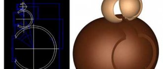
Hi all. Possibly a repeat, but still:
I am attaching a picture with drawings.
Hi all. Possibly a repeat, but still:
Without a doubt. One is more than enough. What gain?
Why does a woofer need thin paper? And why is it thin anyway? But not in stores, because it’s the last century. It has happened and passed, the world does not stand still, it is full of much more serious decisions.
Andrey_N In order not to point your finger at the sky in vain, remove real PTS from real 6gd2, put the data into a program convenient for you, and based on the result you will decide whether the game is worth the candle.
But I couldn’t find an alternative to the 6GD-2, but I was looking. Believe me. Finding a low-power bass speaker with a high quality factor is not as easy as it seems.
Without a doubt. One is more than enough. What gain?
Why does a woofer need thin paper? And why is it thin anyway? But not in stores, because it’s the last century. It has happened and passed, the world does not stand still, it is full of much more serious decisions.
But I couldn’t find an alternative to the 6GD-2, but I was looking. Believe me. Finding a low-power bass speaker with a high quality factor is not as easy as it seems.
, Of our old ones, there is the best alternative to 6GD2 - you didn’t look hard. Siemens ShP has ovals .. HF if Siemens RUF28 is a little better than ours, but up to 12-14 kHz ..
It won't take off. You need a very large box volume. Try 8GD-1-25, but they have less sensitivity. And maybe it makes sense to divide it higher, otherwise the midrange accounts for too much of the power.
Mom is Russian, and dad is also a lawyer. Well, if you don’t pay attention to the confusion from everything German, all three components are worth each other. No, I don’t criticize indiscriminately, for 25 years I dealt with the older ones from the 8″ RFT L2921 line, at that time it was a very good head. So I’m one of my own, just a little boatswain.
This is not a reason to look
, confidently burning at 10W, and even
I understand it's tradition. But, again, why, then start dancing with the PAS and try to squeeze at least 50Hz out of the speakers and so with almost zero movement? Everything is much simpler, take a professional head of at least 10 inches, top-end constitution, the most simple one. Here you have a bass player, only with normal pressure and a setting of 40-50Hz on the shelf. And the body is at most 60 liters.
If you divide passively, it won't work that low. And even with 200, I wouldn’t install such a large head, especially considering your power. In any case, I would make the low-frequency housing separate, so there is less sawing later if something happens.
Both options are wrong, the first one is better, just reduce the height.
All in all. you rejected my speakers and my idea (((where should I put them now?
Hi all. Possibly a repeat, but still:
I am attaching a picture with drawings.
Andrey, you are quoting AS from a series of articles/brochures by Yu.V. Cherkunov about a high-quality amateur electrophone. Written in the mid-70s of the last century. When there were simply no other speakers. The acoustic design in the form of a PA used in this speaker is considered to be very approximate. Even now. And, if necessary, it should be done in exactly this design, modeled/measured/modeled, etc. for a long time and persistently.
Source
2-way small-sized speaker for 6 GD-6 and 2 GD-36 (Saltykov Cubes)
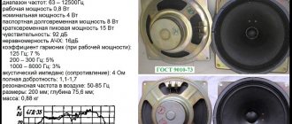
The parameters of the homemade 2-way loudspeaker described below meet modern requirements for small-sized high-quality sound reproduction systems. The loudspeaker is designed to work with an amplifier delivering 10-25 W of power to a 4-ohm load. Two loudspeakers with such amplifiers provide normal level and high sound quality in a room of up to 100 square meters. m, i.e. in almost any living room. The loudspeaker is simple in design and therefore its manufacture is accessible to most radio amateurs.
Options
Frequency range: 40 – 20000 Hz
Resistance: 4 ohms
Frequency response unevenness in the range 50 – 20000 Hz: 8 dB
Filter crossover frequency: 4000 Hz
Low-frequency filter slope: 12 dB/oct
Slope of the high-frequency filter section: 18 dB/oct.
Average standard sound pressure 0.12 Pa
Average reduced efficiency in the frequency range 50 – 4000 Hz: 0.18%
Dimensions (HxWxD): 28x28x21 cm
Weight: 7.5 kg
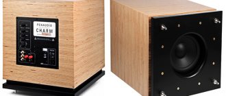
A structurally modified 6GD-6 dynamic head is used as a low-frequency emitter in the loudspeaker, and a 2GD-36 head is used to reproduce higher frequencies. The low-frequency section of the loudspeaker is made in the form of a bass reflex (an 8.5-liter box with a cylindrical tunnel). A properly designed bass reflex allows you to expand the effectively reproduced range towards lower frequencies, increase efficiency and reduce distortion at these frequencies compared to a closed box. Since the depth of the loudspeaker box is small, and the low-frequency head and bass reflex pipe are located asymmetrically, standing waves inside the box are weakly expressed and practically do not deteriorate the frequency response of the loudspeaker. Therefore, in this design there is no need to dampen the internal surfaces of the box. The high-frequency head is mounted in close proximity to the low-frequency one, which reduces the unevenness of the frequency response near the crossover frequency. The large axis of the high-frequency head is located vertically, which allows the radiation pattern to be expanded in the horizontal plane at high frequencies.
The crossover filter consists of a low-pass filter and a high-pass filter; their inputs are connected in parallel (Fig. 1). The separation filter coils are wound with PEV-1 wire on frames machined from organic glass, ebonite, textolite or other insulating material. The coil data is shown in the table, and the dimensions of the frames are shown in Fig. 3. The filter uses capacitors of the MBGO (MBGP) type with claws for fastening and a resistor PEV-7.5 (PE-7.5); instead, you can use three parallel-connected MLT-2 68 Ohm resistors. The wire connecting the filter input to the amplifier must have a resistance of no more than 0.1 Ohm.
Modification of the 6GD-6 head
Some samples of 6GD-6 heads have poorly glued centering washer and the upper side of the latex corrugation “3” (Fig. 2). Therefore, before assembling the loudspeaker, it is advisable to check the quality of the seams and, if necessary, glue them. Defective seams can be detected by lightly pressing on the side of the corrugation in the direction shown in Fig. 2 direction. If the gluing is poor, the seam will come apart. If the length of the seam with a defect is large, you cannot glue this entire area, as this may cause a violation of the centering of the head. The seam should be checked and glued in sections of no more than 30 mm. If a defective seam is detected, the bead of the corrugation should be separated from the diffuser holder “4” in a section no more than 30 mm long. Using a strip of Whatman paper, coat this area with 88-N glue, press the side of the corrugation to the diffuser holder, carefully place the head on a flat horizontal surface with the diffuser down and let the glue dry. Only then can you continue checking the seam. The centering washer is glued similarly to nitro glue for leather, lifting it with a scalpel and pressing it with your fingers to the diffuser holder until the glue sets. The dust cap “2” of the 6GD-6 head is made of a material with low rigidity. As a result, at large amplitudes of vibration of the diffuser, the cap bends inward and then straightens, emitting loud clicks. To eliminate this defect, the cap should be carefully removed using a razor and miniature scissors and a circle of pressed spandex 0.5 - 0.8 mm thick should be glued in its place with nitro glue for leather. The seam must be sealed.
Making a box
To assemble the box, you need to prepare six panels (walls) from plywood or particle board. With a material thickness of 20 mm, the workpieces should have the following dimensions: for the front and rear walls - 240x240; for the top and bottom – 210x240; for side – 210x280 mm. With a different material thickness, the dimensions of the blanks must be changed so that the internal volume of the box does not change. You cannot use material thinner than 18 mm, since the rigidity of the walls will be insufficient. The walls are connected end-to-end with screws 30 mm long with countersunk heads, two screws per edge (Fig. 4). When using particle boards, the holes drilled for the screws (before screwing in the screws) are filled with epoxy glue. Round holes in the front panel (Fig. 5) can be cut out with a jigsaw or drilled with a small diameter drill. The recess for the 2GD-36 head is drilled along the contour to a depth of 15 mm using a drill with a stop, and then selected with a chisel. The bevel of the hole in the place where the 6GD-6 head is attached is necessary to ensure unhindered air movement associated with the rear side of its diffuser.
The tunnel is made of a rigid pipe (duralumin, plastic, etc.) with an internal diameter of 30 mm. The author used a piece of pipe from a vacuum cleaner. You can glue a pipe made of thick drawing paper (Whatman paper) with epoxy glue or nitro glue for leather. The thickness of the pipe walls must be at least 1 - 1.5 mm. The pipe is glued into the hole made for it with epoxy glue and the seam is sealed around the circumference with plasticine (Fig. 5). After this, you can begin assembling the box. If chipboards are used, the inner surface of the box should be coated with nitro paint. All internal seams of the box are coated with plasticine or putty. A separating filter is mounted on the back wall of the box, a wire is attached to connect the loudspeaker to the amplifier, and conductors are prepared for connecting the heads. The distance between the filter coils must be at least 100 mm, the length of each conductor for connecting the heads must be at least 300 mm. The wire for connecting the high-frequency head is threaded into hole “I” (Fig. 5), soldered to the head pins, and the head is mounted on the front panel, as shown in Fig. 6a. The cracks near the head on the side of its magnetic system are also coated with plasticine.
Next, attach the front panel to the side walls of the box (Fig. 6b) and coat the seams between the front panel and the side walls with plasticine from the inside through the hole for the low-frequency head. Finally, the leads of the low-frequency head are soldered, mounted without shock-absorbing gaskets and sealed (Fig. 6c). The low-frequency head is mounted on the outside of the front panel in the same way as the high-frequency head. If the speaker is not properly sealed, the frequency response of the speaker at lower frequencies will deteriorate. Sealing seams and cracks also contributes to good damping of the box walls (they make a dull sound when tapped). The external finishing of the loudspeaker is carried out by veneering, pasting with decorative film or in any other way accessible to the radio amateur. The decorative frame is made from wooden blocks with a cross-section of 15×15 mm, strengthened with duralumin corners. The frame is covered with a nylon mesh, beaded fabric or other acoustically transparent fabric, and is frictionally inserted into the recess formed by the side walls and the front panel. The described loudspeaker, with its small size and low weight, has high quality indicators. Comparison with a unit of a similar class 10MAS-1 showed a significant advantage of the developed loudspeaker. It sounds more natural and bright, without “booming” in the lower frequencies. The wide polar pattern over the entire operating frequency range has a very beneficial effect on the sound quality of the loudspeaker. When playing a monophonic soundtrack, there is almost no “binding” of sound to the loudspeaker, and a pair of such loudspeakers when playing a stereo program provides a very good stereo effect. Instead of a 6GD-6 head, a 10GD-34 head can be used in a loudspeaker without any change in the box design, and a 6GD-11 head can be used as a high-frequency head. When using the latter, a hole is cut in the front wall of the box along the diameter of its magnetic system.
Author of the project: Saltykov O.
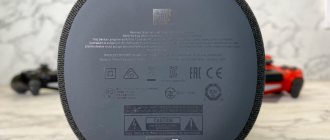
Why was such a low frequency chosen for the junction between the midrange and high-frequency heads?
It's all about the radiation patterns of the 4GD-35. The characteristics of this speaker at angles of , 22 , 45 and 67 degrees are given below. Thus, if you choose a band junction frequency of more than 2 kHz, then a dip will subjectively appear in the 2-4 kHz region - the one that Alexander Klyachin successfully combats with his swing microphone technique when creating 2-way systems.
Rice. 6. Dip in frequency response at the junction of 2-4 kHz
The Agnetta acoustic system uses modified first- and second-order crossovers, the topology of which performs the following functions:
Source