Asalab acoustics - dynamic import substitution
To be honest, I thought that with the rise in the dollar exchange rate and other economically not particularly favorable moments, asalab would grab a significant piece of the market, but for certain reasons this did not happen.
Let's start in order. What is asalab? This is a Kaluga company producing speakers: https://asalab.net/ The company has a fairly serious line of speakers, they used to make even household 12″ speakers, but now their line starts from 10″ (which is also very, very good). The inscription on the website is not very welcoming, but upon request they answer everyone, although not immediately. Apparently some large manufacturer took them into circulation and there is not enough production capacity for everyone. Which is good news. There is a line of whales: Acoustic systems | www.asalab.net
Separately, I would like to note a significant number of different experimental non-serial speakers. I managed to snag a pair of 8″ ones (which will be used for the bass cabinet) and a very interesting pair of 5″ aluminum-ceramic ones (also for the bass cabinet), maybe, if my musician friends approve, I’ll order more for small bass combos.
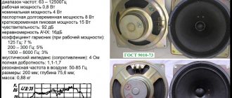
The big plus of the speakers is the price. They are approximately 2-3 times cheaper than imported analogues. I also personally like that the T-C parameters are indicated on the speaker magnet. This is very convenient, especially with non-serial heads. Powerful magnets are often used, my 5″ ones weigh almost 2.5 kg each, although there are also neodymium magnets - they are lighter. Decent displacement, good power, has balls. The resolution is quite sufficient, although lower than the same seas, for example.
There are also disadvantages . Especially such an unpleasant one as the differences in sound from part to part. I had similar problems with the bama, but here they are specifically present. Therefore, if you are a beginner and want to assemble a kit with a more or less predictable happy ending, I would not recommend starting with asalab.
If you want to put together something guaranteed to be good, then I would aim at subwoofers or low-frequency sections. Most likely, low-frequency towers with 4 10″ or 8″ would turn out to be very impressive and quite budget-friendly. I have had positive experience crossing 6'5″ them with a horn beam in a project with Sasha the Shocker. I hope in April you can visit me and listen to them.
Altex knows how to cook them well and I think he has one of the largest experiences in successfully preparing asalabs in Russia.
When I return from vacation, I’ll add a photo to make the topic livelier. If Sasha or Altex want to add something of their own regarding the speakers, I will be all for it. I'll let you know about the topic. You can ask questions.
3-way spherical speaker on ACAlab speakers
This madness began at the end of February 2005. That was the first time I went to the Hi-Fi Show. I just finished my first homemade speakers - three-way speakers on cheap speakers in solid beech cabinets. At the exhibition I listened to almost everything I could. The systems that impressed me were built using acoustics from Bosendorfer, Tannoy, BC Acoustique, PMC. But I was truly blown away by Sound-e-Motion. “Torn from the speakers”, very natural, lively sound. Awesome, unique appearance. Sky-high cost. But I completely agree with the Belarusians in their pricing policy. Making such acoustics is incredibly difficult. But then I had no idea of the amount of work, and by May I had already decided on the design and speakers.
Since a normal student cannot have money for Scan-Speak, speakers from the Kaluga company ASA
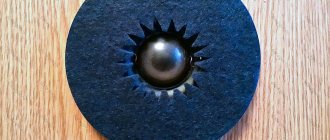
– paper low-frequency driver V2512.8 and mid-frequency driver MP1314.8 (actually, initially I wanted to use MP1314.8P - with a phase-leveling bullet, but at the time of ordering they were not available, and ASA’s people were not going to produce them in the near future), as well as a silk tweeter NEO T26.8 with a special small mounting flange. A classmate who was well versed in Autocad helped me with the drawing. Having determined the volumes and radii of the balls, we created three-dimensional models and combined them in such a way that the acoustic centers of radiation were on the same vertical. It was decided to fasten the balls together using “balts” (in a certain place the surface of the ball was cut off to obtain a flat circle of a certain diameter, a hole was drilled, the balls were fastened with glue and a massive bolt - I think the photographs will explain better). Autocad provided all the required dimensions and provided the opportunity to evaluate the appearance of the enclosures in advance. The rings were calculated “on paper”, using a pencil, ruler and compass.
The speakers were ordered and received, copper and capacitors were purchased, the session was completed - and so, at the beginning of July, I left for my small homeland, Pyatigorsk, with huge trunks.
The technology for making balls is well described here, so I will only talk about some important points.
There were some doubts about the case material: MDF turned out to be impossible to obtain (and, in my opinion, it is not suitable for this technology). Chipboard is relatively cheap and available, but not environmentally friendly and requires puttying and painting. It’s easier with plywood, but it’s more expensive, absorbs vibrations worse, and the striped cut pattern is also not for everyone. With solid wood, getting a chic appearance is not a problem, but it is very expensive and difficult to get large quantities of any wood other than pine. In addition, it is impossible to saw rings with a diameter of 50 cm from solid wood, and dividing the rings into segments and then connecting them is labor-intensive. And the vibration absorption is even worse (although this does not in the least prevent my first speakers made from solid beech wood from playing energetically and lively).
As a result, it was decided to make the largest, “low-frequency” ball from 16 mm thick chipboard, the middle one from 12 mm plywood, and the small one from solid beech.
To reduce waste, the rings were calculated all at once. However, look at this photo, everything beyond the stairs is waste!
The calculated wall thickness of low-frequency balls is 20 mm, of mid-frequency balls is 15 mm. It may seem that this is not enough, but, firstly, the spherical shape of the body implies a much more uniform distribution of pressure on the walls than the standard rectangular one; secondly, the structure is layered, plus a bunch of screws inside; thirdly, the walls from the inside remained stepped, therefore in most places the wall thickness is greater than the calculated one. In general, the balls turned out to be very durable, heavy and rigid (the midrange is actually like a stone!).
One and a half standard sheets of chipboard were used for the LF balls and “pedestal” disks. The rings were cut out using a jigsaw with branded Bosch saws for figure cutting on wood (about thirty of these files died - 150 rubles for 5 pieces!). As the diameter of the ring decreased, the inclination of the file increased accordingly (another mistake of mine - it is more difficult to cut at an angle, the files overheat and break faster - it is better to cut normally, and knock the corners later, especially since it was still not possible to get an accurate joining of the rings). To improve the appearance, and also to ensure that the woofer was flush with the ball, the final ring was cut from 8mm plywood.
In this photo the speaker is protruding above the plywood,
since the hole for it has not yet been processed.
Cutting out mid-balls from plywood turned out to be much easier, despite the smaller diameter, and the saw blades lasted longer.
It took about 400 screws and a liter of PVA glue to fasten the rings together.
Just sawing and gluing large balls took more than two weeks with very intensive daily work of two people (during the entire work on the speaker, my grandfather helped me, for which I thank him very much!).
I first brought the resulting angular “figs” closer to the shape of a ball using a “grinding plane”, but it turned out that it was much easier to do this with the help of a grinding attachment on a drill and the largest sandpaper, such a large one I have never seen before, the grain size is about 2 mm (and a very significant amount of this skin was used). Then the large balls were covered with “Primer” (white thick paint) and, when dry, treated with finer sandpaper. I simply wasted my time on normal putty (WASTE!!! Only putty and sanding can even out uneven spots and cavities in chipboard!).
Finding a person in our city capable of turning small balls out of wood turned out to be problematic, and in the end, a certain man turned not balls, but something egg-shaped, and not from a single piece of wood, but glued together from halves, but oh well.
To install the balls on a pedestal at a sufficient height from the floor, three stair balusters of the most sane design that could be found on our market were purchased. Each baluster was sawn in the middle at an angle of 45 degrees and then the cut surface was adjusted to fit the ball “in place” (a very labor-intensive operation). The balusters are screwed to the pedestal and ball with huge screws and mounted on super-PVA (during final assembly).
Unnoticed, the end of August approached... We assembled one speaker, so far only with screws and bolts, I soldered the crossover. The bass reflexes were made from a plastic sewer pipe called “weaving” and brought down. The sound is natural, so-so, the filters are “approximate”. The only thing I liked at that time was that the sound seemed to come from one point, and not from three speakers.
The speakers were completely disassembled, I covered the inner surface of the balls with a good layer of automotive rubber-bitumen mastic, and, leaving them stinking in the summer kitchen, I left for Moscow - the fall semester began.
I don’t know exactly how long the mastic smelled, but at least a month – that’s for sure! By the way, at the same time I smeared it on the bass reflex pipes and the ringing stamped baskets of the woofers. I don’t know if this makes sense, but it certainly hasn’t gotten any worse.
I resumed work in January. The mastic had already dried and hardly smelled, but it still caused a lot of trouble during assembly. All the necessary flats and holes were made on the second speaker. The connection terminals are located in the “pedestal”, which also contains a crossover (this is very convenient and does not take up the useful volume of the low-frequency section). The only problem is feeding the wires into the ball. A metal tube was placed behind one of the hind legs, with 6 wires running well inside it.
The LF balls were painted with high-gloss alkyd enamel in 3 layers. All wooden parts are coated with one layer of nitro varnish to protect the surface from contamination during assembly. I left to take the exam.
After 2 weeks the session was over, the paint had dried well, and I returned home. The time has come for the final assembly of the “speakers”. The legs are glued to a super-PVA “pedestal” (unpainted spots are left under the legs, of course), and secured with screws. Large balls were installed on the legs through putty mixed with PVA, and the putty was painted. MF balls are installed on large balls, again through putty. On top there are small balls. The entire assembled structure is coated with high-gloss alkyd varnish in two layers. Varnish adheres to paint much worse than wood.
I filled the low-frequency balls with padding polyester. The midrange balls are filled with MEGA-HIGH-END material - my cat's fluff, combed into a bag for six months. All cables are Litz wire 117*0.07.
The crossover was done like this: from a distance of 1.5 meters on the HF axis, using the JustMLS program and a microphone on the WM-60 capsule, the frequency response of the speakers installed in the speaker cabinet was measured. The measurement results were imported into LSPCad, where the crossover was modeled and optimized. Then – emulation using LSPCad, assembly, and minor fine-tuning by measurements and by ear.
The crossover uses almost exclusively domestic components - MBGO, MBM, MBGCh, FT3, K73-17, K73-16, K78-2, copper wire. Imported - only resistors (by the way, the divider was only needed for the tweeter). All coils - with an air core, except for the pass-through at LF - required low resistance, so 5.26 mH was wound on an open core from the transformer. No “iron distortion” was noticed by ear. I measured capacitance and inductance using a sound card, the LCMeter program and a simple device.
I didn’t have time to particularly evaluate the sound, since I went to Moscow again to study. But, according to first impressions... super! I can’t describe it in detail, and there’s no point in doing so. I’ll probably redo the filter and try different options...
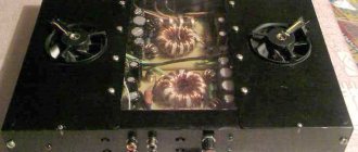
The two boxes in the middle are my homemade amplifiers, the bottom one is just for these speakers.
And now let me give some advice to those
who would dare to do something like this:
1. Weigh the amount of work well and decide whether you need it.
2. Make the entire body from one material, either painted or varnished.
3. Make the body monolithic, that is, there are as few glued joints as possible, such as ball-to-ball or leg-to-ball.
4. Good tools and materials will save you a lot of time.
5. For a jigsaw there is a device for cutting in a circle - probably a very useful thing.
6. Immediately mark the locations of the holes in the housings so that when drilling you do not hit the screw.
Project author: Yaroslav Parshin
2006