Guitar amplifiers, along with electric guitars themselves, have always been of interest to many beginners and not only musicians. Timbre, gain and overload characteristics are very individual, and the ideal combination varies from one guitar to another. There is no amplifier that completely satisfies all requirements, and this circuit proposal will not be an exception. But it is universal, powerful (about 100 watts) and has all the necessary adjustments. Unlike a store-bought amplifier, if you build a VLF yourself, you can change many things to suit your own needs. The opportunity to experiment is presented in full. And it’s much more honorable to play on your own equipment, because our individuality is manifested primarily through creativity. The proposed guitar amplifier is designed for 100 W of power into a 4 Ohm load. This is the usual power for guitarists, which is enough for both home and concerts.
Guitar preamp - circuit diagram
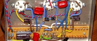
We solder the guitar pre-amp on a separate board, later placed in an interference shield. A photo of the preamp board is shown below. It is based on two operational amplifiers with a tone and gain control unit.
This is a simple but proven circuit design that provides excellent tonality throughout the entire range. The design is ideal for those guitarists who would like to get great sound. The tone controls have enough range to cover almost anything, from violin to bass guitar.
The preamplifier uses dual op-amp for amplification. The transistor is connected according to the emitter follower circuit and has a low output impedance, after the master volume control. As shown in the diagram, there is a typical guitar input from which you can get a very fat overdrive and then adjust it to a suitable level. Please note that when using the TL072 op amp, noise with a lot of high frequencies is possible. We highly recommend using the OPA2134 op amp from Texas Instruments for truly the quietest guitar amp you've ever heard!
The module's power is connected directly to the main +/-35 V bus of the power amplifier. You need to use 1 W zener diodes (D5 and D6), and 680 Ohm resistors R18 and R19 should also be 1 W each.
For greater gain, we recommend reducing R11 to at least 2.2 kOhm. If the bright switch makes the sound too bright (too much high frequency), you need to increase the resistor R5. The output diodes are designed to allow the preamp to create "soft" clipping as the volume increases.
Make sure the input connectors are isolated from the chassis. This helps prevent noise, especially when the guitar amp is connected to a different power source.
Tone control
The passive tone control corresponds to the classic simple and effective solution, which creates a wide variety of frequency response of tones.
The circuit is a combination of a high-pass filter (C1, R5) and a low-pass filter (R4, C2), which are mixed together by a linear potentiometer POT1. The cutoff frequencies of both filters are designed so that their mixing effect introduces an average cutoff frequency at 800 Hz when the potentiometer is set to the middle position.
Amplitude-frequency characteristic of tone adjustment:
The green response line is the tone control set at the midpoint indicating the 800 Hz frequency band. The total loss is 7 dB, and about -10 dB at 800 Hz. The blue and red curves correspond to the full low/high frequency range, respectively.
To produce clean sounds, it is best to use a potentiometer closer to the higher frequencies, this will reduce the overload of the bass signals, and the resulting sound will be brighter and clearer. Either position will work for rock/hard/metal playing, the distortion will be heavier in the bass and more punkish in the highs.
Amplifier
The photo below shows a fully assembled UMZCH printed circuit board. The TIP35 and TIP36 output stage transistors ensure reliability in the harshest stage conditions. Other features of the circuit include short circuit protection - bias components of diodes D2 and D3.
Short circuit protection limits the output current to a relatively safe level. The protection will limit the peak output current to approximately 8 amps. The bias current is adjustable and should be set at about 25 mA at rest. Transistors TIP3055/2966 or MJE3055/2955 can also be used for UMZCH. The circuit allows you to connect up to two 8-Ohm acoustic speakers (4 Ohms each). Do not use speakers less than 4 ohms into this amplifier - it is not designed for such low impedance!
ULF power supply
The power transformer should be toroidal for best performance and minimum interference. The amplifier is designed for a maximum supply of +/-35V and this value should not be exceeded. The transformer should be rated for 25-0-25 volts, and no more. Less is fine if you don't need the full 100 watts. The transformer power should be 150VA (3 A secondary current). More than 250VA is overkill. Use good quality PSU filter electrolytes as they will be subject to current and temperature stress. The current of the diode bridge rectifier should be 35 A. Mounting type - on a chassis with thermal paste.
All fuses must be as specified in the diagram - do not be tempted to use larger ones. The input and output connections are shown in the figure.
Preamp out and power amp in jacks allow you to insert effects such as compression, reverb, digital effects and others into the audio path. The preamplifier output is connected so that the preamplifier signal can be removed without turning off the power amplifier, so it can be used for direct audio supply. This is especially useful for bass. The preamp output can also be used for another power amplifier.
Output attenuator LM386
The output power of the LM386 is too high for headphones. Typically, headphones only require 1 mW (at 32 ohms) for reasonably good volume. Depending on the power supply, the LM386 can output up to 1000 mW (1 W), so a series resistor is installed to reduce this output power below a threshold. This auxiliary load will take on part of the power, transferring only the required amount of energy to the headphones.
Amplitude-frequency characteristic of the output attenuator:
Installing an output attenuator will change the frequency response, reducing the amount of bass in the headphones.
Without attenuator (purple graph): There is a low-pass filter formed by C7 (220uF) and the speaker load, the cutoff frequency is 90Hz, harmonics below 90Hz will be attenuated. Guitar signals do not contain much sound at these frequencies. In fact, if you have a small speaker and it is overdriven, you should reduce this limit to about 100 µF.
With an attenuator (blue and red graphs): an additional resistor connected in series and a load (32 Ohm headphones) will attenuate low frequencies below audible frequencies. For this series resistor, any value between 300 ohms and 1k ohms will reduce the volume to an acceptable level for most headphones. Some people only use a 10 ohm resistor, but the volume is still too high.
Setting up a guitar amp
- Before the power is turned on for the first time, temporarily install 22 ohm 5 W resistors instead of fuses. Do not immediately connect the load (AC)! When applying power, check that the DC output voltage is less than 1 V. Check all transistors for heat - if any element is hot, turn off the power immediately, then look for the error.
- If everything is fine, connect the speaker system and signal source and make sure that the sound is not distorted (for example, connect music from the player).
- If the VLF passes all these tests, remove the 22 ohm resistors and reinstall the fuses. Disconnect the load speaker cable and turn the unit back on. Make sure that the DC voltage at the AC terminals does not exceed 100 mV, and again check the heating on all transistors and resistors.
- Once you are sure everything is good, set the bias current. Connect a multimeter between the collectors of Q10 and Q11 - you are measuring the voltage drop across two 0.22 ohm resistors R20 and R21. The required quiescent current is 25 mA, so the voltage across the resistors should be set to 11 mV. The value setting is not too critical, but lower currents will result in less dissipation in the output transistors.
- After this, it remains to adjust the offset when the temperature of the body and all parts of the guitar amplifier stabilizes. Often temperature and current are slightly interdependent. That's all - the design is ready!
Originally posted 2019-05-03 05:59:24. Republished by Blog Post Promoter
Add a link to a discussion of the article on the forum
RadioKot >Schemes >Audio >Amplifiers >
| Article tags: | Add a tag |
Transistor guitar preamps with tube frequency response
Author: [email protected] @, Published 04/23/2015 Created with the help of KotoEd.
Having learned that some radio amateurs neutralize the sound of 6n2p (by soldering a capacitor to the grid and anode) making it similar to 12ax7, I decided to look into this in more detail. The fact is that the signal reaches the lamp grid through a resistor (in most cases), so an RC filter is formed consisting of this resistor and lamp capacitances. The main influence on the cutoff frequency of this filter is exerted by the anode-grid capacitance, as it creates an equivalent capacitance at the lamp input (Miller effect) that is N+1 times greater (N gain). That is, in order to repeat the frequency response of a lamp stage, you need to replace the lamp with a transistor with the same gain and drain-gate = anode-grid capacity. But not all transistors have this capacitance less than the required one (= 3pF), the more powerful the transistor and the higher the gain, the greater the capacitance.
And in order to use such transistors, it is necessary to change the ratings of the RC circuits of the entire circuit, multiplying and dividing them by the total number. For example, the diagram below shows an example of recalculation of a simple cascade and frequency response.
In the transistor version, all resistances were divided by 3 and the capacitances were multiplied by 3. The resulting frequency response of the 2sk170 cascade is closer to 12ax7 than 6n2p. It is also clear that in 6n2p the RF roll starts much higher than required, this can be easily corrected by connecting a 3-4pF capacitor to the anode and grid, and the gain cannot be raised to 3.5 dB lower. In short, to scale, you need to proceed in the following order: 1) select a drain resistor at which the gain of the stage on the transistor is equal to 68 (12ax7) or 46 (6n2p) or within these limits. 2) find the number K for recalculation; to do this, divide 100k (usually this value at the anode in tube circuits) by the found resistor 3) multiply the circuit capacitances by K and divide the resistances by K 4) assemble the circuit and level the parameters of the cascades; if the gain is very large, then set R2, if a lot of HF passes through, add capacitor C8
The capacitance of C8 is equal to 3pf*K minus the internal capacitance of the drain-gate transistor, the capacitance of the transistor can either be looked at in the parameters or measured through the battery (to eliminate the varicap effect) figure below
Below is an example of a circuit ported into a transistor (links to the original https://www.ampbooks.com/mobile/classic-circuits/soldano-slo-preamp-1/soldano-SLO-schematic.jpg https://www.prowessamplifiers.com /schematics/misc/Soldano_SLO100.html )
I multiplied/divided the denominations by 2.5, not all denominations can be purchased, so you can replace them with the closest ones. In the first and fourth cascades I installed some kind of domestic field switches of unknown markings, I added 7 pf to the drain gate, in the second stage I put 2sk170BL, in the third stage you can put almost any field switch, neither capacitance nor gain play a special role there. The setup is to get half the power supply at the drains of transistors 1, 2, 4 voltage stages, this can be achieved with trimmers R23, R24, R25 (value of trimmers 15-100k). This type of bias reacts very strongly to the supply voltage, so if the voltage on the stabilizer changes, these resistors may have to be adjusted again. At the drain of the 3rd transistor, the voltage should be slightly less than the supply. You can also check the gain of stages 1,2,4; it should be approximately 40-60 times if you apply 1 kilohertz to the gate of the transistor for amplification. Since the supply voltage of the transistor circuit is about 10 times lower, the input signal should be the same amount of times lower, for this I added a divider R27R3 to the input, the resistance of R3 is enough to block the RF and R2 is unnecessary, so I closed it with a jumper.
The preamplifier is connected to the amplifier, so the following is the amplifier circuit. I have already posted a circuit before (link https://radiokot.ru/circuit/audio/amplifier/71/), and recently I added to it. picture below
I replaced the input stage with TL071. Added OOS to suppress low-frequency resonances R13R12C9C10. Added snubber R14. L1 - neutralizes the frequency response of the speaker; the fact is that (especially for a guitar sound) the speaker has a larger one and an inductance of as much as 0.4 mH, respectively, and it dampens the HF better and the sound is softer; in addition, the leakage inductance of the transformer is added to this inductance. But this does not mean that any speaker can be fixed this way……………….
Basically, the setting comes down to selecting L1, C7, R14 for the desired timbre by ear. L1 can be wound on a ferrite ring, for example, on a ring with a diameter of 4 cm (with a permeability of 2000), literally 10 - 15 turns must be wound to obtain an inductance of 1 mH.
Audio recording below (circuit guitar (singles)>preamp>amp>8″ speaker in a small “box” so there’s not much bass)
https://yadi.sk/d/yxbQya1Vg2sbD
All questions in the Forum.
| What do you think of this article? | Did this device work for you? | |
| 12 | 8 | 8 |