At the same time, I still have very good memories of the operation of this amplifier on homemade 3-way speakers in the past. Is it worth bothering with such a miracle?
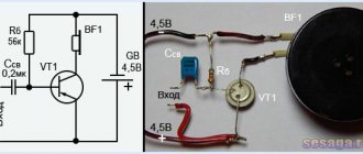
Also on this fragment of the diagram the relay and its contacts are indicated.
TIPTONIK, I’ve been waiting for this Amphiton for a year to finish the same as in the article, I have postponed the finalization for an indefinite period - there were problems with stability; and to be honest, I lost interest in it a little - everything stopped at the production of new terminal boards, since relatives simply began to fall apart; If you get around to finishing yours in the same way, I’d like to see the results - maybe I’ll finish mine too. Some people bypass capacitor C1 with a film one. Restoration of Amphiton 50UM-104S
The amplifier is not designed to operate from EMI, microphones, piezoelectric pickups or radio broadcast networks. Pay attention to the cross-section of the wires, but more on that later.
I have only two options: - perhaps additional windings were connected to increase the supply voltages of the power amplifiers, and accordingly - increase the output power; — perhaps the transformer was completely changed, or one of the windings was rewound.
Point seven: I have never liked electrolytic capacitors at the input of a power amplifier. Along the way, I rang the transistors that came to hand, mostly without soldering them; I rang the ones I unsoldered, checked the gain with a multimeter, soldered them back into the power amplifier blocks, and rang absolutely all the transistors.
In this form, the amplifier turned on, the protection did not work, which was already pleasing, one channel worked, but played quietly, the second was silent. If everything is clear with the first one, then what they did with the transformer is not completely clear.
Inside, you can consider the division of individual blocks into compartments that separate the metal walls. Point three: on the rear panel of the amplifier there is a toggle switch that switches 2 sets of speaker systems on the amplifier.
Restoring the Radiotehnika U 101 stereo amplifier
You are here
Replacing electrolytic capacitors at the input of a power amplifier on Wima. Upon closer examination, it was noticed that one output transistor and a heavily soldered transformer had been replaced before me. Like C1 in our amplifier. The overload detector is triggered by a constant voltage at the output, and judging by the hum, it is most likely there.
Upon closer examination, it was noticed that one output transistor and a heavily soldered transformer had been replaced before me. Let's go for the scheme!!! At my place, I disconnected and discarded the shielded signal conductors leading to these sockets, eliminating unnecessary signal wandering.
Along the way, I rang the transistors that came to hand, mostly without soldering them; I rang the ones I unsoldered, checked the gain with a multimeter, soldered them back into the power amplifier blocks, and rang absolutely all the transistors. But this is unlikely, and is a consequence of the death of the output. Point one: instead of dried capacitors C1-C8 μF, which amounted to μF in each arm, we install μF x 63V in each arm. Something else. The bottom of the amplifier is metal, convex with perforated holes. I would like to have a circuit and measure the modes in cascades. I destroyed this circuit. Repair, restoration of player Russia 325С
Appearance and Design
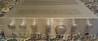
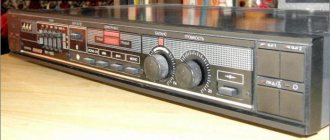
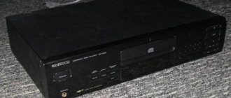
The Amphiton-002 Stereo amplifier looked very impressive. It is made of thick metal. Moreover, metal covers it on all sides. The front panel contains controls. What catches your eye here is the huge volume control knob. This is very convenient, since you can freely navigate the controls in complete darkness. The side faces of the device serve as a heat sink and have a ribbed surface. This gives the amplifier a somewhat futuristic look. He looks powerful and dignified.
On the rear panel there is a set of connectors, a speaker switch and an additional power connector. Amphiton-002 Stereo weighs 9 kilograms. This is a decent result. Any high-quality amplifier is quite heavy, since its components are far from budget. On the top panel, which is also made of a single sheet of metal, there are “gills” for the cooling grille. This allows heat to be dissipated more efficiently from the amplifier components. However, let's move on to other features of this device.
Hellraiser, or the return to operation of the Amphiton 50U-202C amplifier
I didn’t do this, I’ll tell you why below. For the linearity of the output stage, this is not the last thing. In addition, I made certain changes to the protection circuit, namely, I removed the protection for exceeding the output power, I did not touch the excess indication, leaving only the protection of acoustic systems from constant voltage at the output, because no one wants a burnt-out transistor in the output stage to be dragged to the grave by another and column.
Knobs and buttons are made of cast aluminum.
As for loudness compensation: In order to shift the boost frequency towards low frequencies, I increased C1 from 0.22 to 0.33 µF. If you are satisfied with these characteristics, it is better to skip this part. The background and extraneous crackling disappears after the shielding cover is closed; it is mainly “caught” by the tone block board. Moreover, the lightness and transparency of the sound on acoustic jazz and classical music does not prevent them from performing Metallica and Manowar with sufficient drive.
Amplifier circuits
Even when purchasing, I noticed that it had obviously been opened. There are no extraneous sounds to the ear at any volume; I listened to both music and test discs. The background is like never before. The side panels are aluminum, they simultaneously serve as radiators and external walls. There was little bloodshed.
Message from rippi throw abstruse thoughts and words out of your head. Maybe gut it right away and use it as a good case with a ready-made transformer for a homemade amplifier?
Reality has made adjustments. Replacing the relay of the protection circuit and changing the functionality of this circuit. My Amfiton 25U 002S
Tuning (revision) of the Amphiton-U-002 amplifier. Version of the scheme "2021".
Modification of UMZCH Amfiton-U-002. Increasing the rate of rise of the output voltage. Horror stories about frequency correction. Lots of graphs and diagrams. Designed for a very prepared reader. 1.
Amphiton amplifiers in the former USSR. The start was made in 1978, when the author’s Hi-Fi amplifier circuit was published in Radio No. 6 magazine:
An article about this: Soviet HI-FI and its creators Shushurin - Lamm.
Under the leadership of V. Shushurin, the following amplifiers were created: - AMPHITON A1-01-2u stereo 1982 - AMPHITON-U-101-1 stereo 1982 - AMPHITON-AI-01-1 stereo 1982 - AMPHITON-U-002 stereo 1983
Links to descriptions and diagrams: UM Amfiton-U-101-1 UM Amfiton-U-002 UM Lort 50U-202S
2.
Frequency correction (FC) in amplifiers covered by negative feedback (NFC).
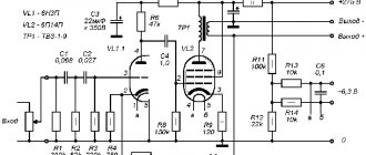
As a teaching example, the circuit of a simple mind control is borrowed from volume 1 “The Art of Circuit Design” (Horowitz P., Hill W., 3rd edition, 1986; there is also a detailed description of the circuit):
As a “measuring” tool - the Multisim 10 program:
The diagram is “assembled” as close as possible to the original source. Load - 32 Ohm. The gain is set to 20 dB. Additionally, the zero at the output of the PA was balanced by “adjusting” some resistors. There is no frequency correction in this circuit. Frequency response:
The unity gain frequency f₁ is almost 26 MHz. Not bad for an audio amplifier. )) Let's look at the speed: 14 V/µs at the leading edge of the phase response response:
The phase shift at a frequency of 26 MHz has crossed the 180 degree mark!
This means that when assembled live, this circuit will turn into a generator with a 90% probability.
To prevent this from happening, frequency correction (FC) was invented. Capacitor C1=620 pF is the CC element (in this case, the so-called single-pole correction).
As a result of the frequency response: Frequency f₁ shifted down to 3.6 MHz. Phase response: Phase shift by f₁ minus 123 degrees.
Thus, the stability condition was met: the phase margin at the unity gain frequency must be at least 45 degrees
(i.e., the phase shift should be no more than 135 degrees).
In simple terms, the speed of the amplifier was “strangled” so that the amplifier was just an amplifier, and not an RF generator. After applying frequency correction, the slew rate of the output voltage (SR) is reduced. This is the price to pay for sustainability.
Let's see what happened with the slew rate: only 1.6 V/µs. Well, who needs such a PA?
The task of the UM developer(s) is to come up with a scheme so that it 1) satisfies the requirements of GOST (this is the whole set of characteristics: Kg, IMD, SR, etc.) 2) does not cause problems during setup 3) is more or less reliable in operation
To sleep peacefully at night, the developer introduced excessive frequency correction into the circuit
. Naturally, to the detriment of other characteristics. As shown above, the slew rate of SR was cut off first.
He can be understood. If the PA “whistles” due to insufficient RF, the owner has a chance to part with not only the amplifier, but also expensive speakers (the HF speakers will instantly receive a fur-bearing animal).
Additional Information
Amphiton serial amplifiers were no exception to the rule: there is excessive frequency correction. That's why…
For those who want to familiarize themselves with this topic in more depth: “The Art of Circuit Design” Volume 1 Horowitz P., Hill W., 3rd edition, 1986. “Frequency equalization of amplifiers with feedback” (page 230 ff.)
3.
Output slew rate (SR).
The high rate of voltage rise allows you to more accurately and quickly correct errors in the OOS circuit. It is important that the phase shift is minimal. There are many other reasons why high speed is important.
Vmin =
2*3.14*20000Hz*30V = 3.8e+6 V/s (or 3.8 V/µs) where 20kHz - Fmax 30V - amplitude output voltage
In practice, the PA must have a certain safety factor for speed. If we take the reserve factor equal to 3, then for a conventional PA the minimum value of SR should be at least 10 V/µs.
I have more than once come across the opinion that amplifiers with SR less than 10 V/µs do not play. I have to agree.
There are many options for frequency correction. The difficulty is that theory is not very friendly with practice. It turns out that the same CC method in different schemes gives different results. Those. frequency correction cannot be considered (calculated) separately from the rest of the circuit.
4.
The Advance Acoustic MAP-101 amplifier came to my audition along with the JLH 1969 (see the beginning of the review).
The sound is the most ordinary. A couple of quick measurements. THD into 4 ohm load: 6.7 V/µs slew rate:
The price range is $300, and such mediocre characteristics.
Conclusions:
1. Frequency correction in all its glory: the speed is cut off. 2. Purchasing a branded device does NOT guarantee the desired result.
Well, really, who will allow me to listen to every amplifier and connect all sorts of techno-horror to it. But they don’t send me such devices for testing free of charge. (
5.
Offtopic
I foresee comments along the lines of “This is all a waste of time. Buy everything ready-made and don’t worry.” Thanks, not my way. I'll try to explain my point of view. To buy an amplifier and not put it on Avito or Olkh in a week, you need to: - before buying, listen to the amplifier with its own set of acoustics (without haste, of course) - listening should be carried out in a prepared room, and not on the counter next to mixers and vacuum cleaners - it is advisable to do some interesting measurements (SR, THD), so that there are no surprises later - if you buy a used one, it is advisable to open the hood, lift the lid and make sure that the amplifier has not been tinkered with with crooked hands
From this small list, we will fulfill only the 1st point, provided that the amplifier is purchased in a specialized salon/store. The last three points are difficult to implement or even impossible to implement for a number of reasons.
Thus, buying an amplifier that claims to have an interesting sound becomes a difficult task for the average buyer. For example, the city where I live (population 100 thousand) is a typical periphery: there are no audio salons. Tips like “take the bus and go to Kyiv\Kharkov” - “to the garden” ©. The same goes for buying a used one.
It turns out that in my case it’s easier to roll up my sleeves, turn on the soldering iron and do something myself.
6.
“Acceleration” of the Amphiton-U-101-1 UM and what came of it. The diagrams (published in 1978 and the diagram of the serial Amphiton-U-101-1 UM) are twin brothers.
CHK elements: - capacitor C5 (its position is surprisingly the same in both circuits) - R4, C4 (according to the 1978 circuit) - C7 (according to the Amphiton-U-101 circuit) The developer did an excellent job: phase shift by f₁ minus 85 degrees, but the speed is only 5 V/µs.
When using NI Multisim 10, the “overclocking” of the Amphiton-U-101-1 PA circuit was successful: see the review and diagram of the Amphiton-U-101M PA. The value obtained is SR=20 V/µs.
7.
UM Amphiton-U-002. We will only talk about finalizing only the final mind. In my instance, all other nodes have long been disabled. All the knobs and buttons on the front panel (except for the “on/off” button are a sham).
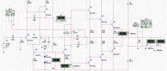
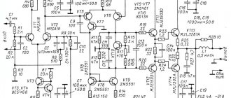
Factory diagram: From another source (better quality):
Frequency correction is performed in a completely different way: - R6 and C4 between the collectors of the input differential stage transistors - C6 in the OOS circuit - C8 and C9 - R23 and C10
For modeling, an inverted circuit was assembled (this is when pnp transistors are replaced with npn, all polar elements are “turned” by 180). The input low-pass filter (R1 and C2) has been removed because it is not covered by general environmental protection. Frequency response:
f₁ = 2.7 MHz phase response:
The phase margin is only 15 degrees. And how did the quality control department let this scheme go into production? ))
Slew rate - only 6 V/µs:
I’ll leave the “measurements” in the simulator for a while to find out who previously modified Amphiton-U-002...
8.
Author's modifications to the Amphiton-U-002 UM circuit to improve performance. Extensive work in this direction was carried out by the author of the article “Overclocking of Amphiton or another blow to the tambourine of the High End” (magazine “Radio Hobby” No. 5 in 2008)
Additional Information
The author came into the hands of the Amfiton-25U-202S UM, the design of which coincides with the Amfiton-U-002 UM. What differences there are in the schemes and whether they exist at all is not fundamental.
Even I had difficulty following the train of thought, experiments and measurements when presenting the material. Respect to the author!
The final scheme that the author arrived at: Changes in the scheme are marked. Probably enough graphs. Simulation results: - f₁ = 6.8 MHz - phase shift by f₁ minus 200 degrees - speed SR = 22 V/µs The author coped with the task, with the exception of the stability problem.
9.
It was only after the New Year that I managed to return to my Amphiton-U-002 amplifier. At the end of 2022 The EEA project was unfrozen from the archives. Since both the PCB and the modeling of the nodes were ready, all that remained was to solder everything and try it. In short, on January 1, 2021, at the final setup stage, the idea failed. Complete. (The EEA project was again frozen indefinitely.
For the sub you need a trouble-free amplifier. There is just Amphiton-U-002 in the house.
The amplifier was tested with a tone burst of 40Hz 100ms (level in SpectraLab -3 dB) into a 4 Ohm load:
Norm. Level -1.5 dB:
Very bad. (
I opened the lid and looked at the power supply with an oscilloscope. No load (power line +27.5V):
But under load: Something needs to change.
10.
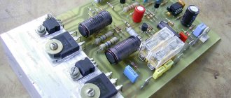
The first step towards improving the characteristics of the Amphiton-U-002 Amplifier. Well, of course, replacing power supply capacitors. Each channel contains four 2000 uF*50V capacitors (two capacitors in each power line). It was decided to replace every 2nd 2000 µF capacitor with a new 10,000 µF * 50V.
It took about 4 hours to replace four capacitors. Unsoldering the wires turned out to be not easy: the leads were simply torn out of the old capacitors, because... the conductors are bent with a hook and covered with solder. Here are the four after dismantling:
Right channel of the PA after replacing capacitors: What is the result? +27.5V line under load:
Tone Send -1.5 dB:
Norm.
Tone Send 0 dB:
By replacing the capacitors we were able to add +1.5 dB for maximum power.
11.
Hmm..., oh, what am I talking about Morning 01/2/2021. The amplifier stands on a desktop without a top cover. Everything is in place for further work with him.
Specifications for revision:
- increase slew rate (SR) to at least 15 V/µs - improve stability if possible - minimum changes in the original circuit (i.e. no replacement of transistors with modern semiconductors)
Why exactly this 3rd point? It’s simple: in order to “plow up” the PA boards, you will first need to remove them from the case. And this is not easy. Of course, you can do this quickly with side cutters. How to get back?
12.
Amphiton-U-002-2021 amplifier input stage. Before doing frequency correction, you need to clarify something according to the factory diagram (see point 7).
Current sources (on transistor VT3) are a misunderstanding. Because the transistor KT315 (VT1) is used as a zener diode. Firstly, this is not a passport regime. Secondly, what is the voltage on this “zener diode”? In order not to get lost in guesswork, live measurements: the voltage drop across R7 in the LC is 7.16V, in the PC - 6.5V. Accordingly, the IST current is: 2.2 mA (LC) and 1.97 mA (PC).
Which of the two values is closer to what the developers intended? Fz. Let it be 2 mA (1 mA per arm of the diff cascade).
For further work, the input stage was “separated” from the rest of the circuit in order to determine the changes:
An IST has been assembled, providing 1mA to the arm. All other elements are unchanged. There is no OOS.
The circuit is “skewed”: the output is -30V.
Yes, OOS will fix everything, but the input stage will work with skew.
After simple changes, the input stage was balanced:
But the IST value had to be increased to 2.5 mA.
13.
Only now can we begin frequency correction.
The so-called "correction 2C
". First - without OOS:
The resistors connecting the bases of the diff cascade transistors to zero have been replaced with 1.8 kOhm. It's not a mistake. More on this later. Resulting phase response: Super!
14.
Now we integrate the new input stage into the amplifier circuit:
The amplifier is naturally covered by OOS. Therefore, the phase response has changed: The unity gain frequency is 5 MHz.
Please note that the divider in the OOS circuit is 1:9 (the gain is reduced to 10, i.e. only 20 dB). These are 2 kOhm and 18 kOhm resistors.
The output impedance of this divider is 1.8 kOhm
. Therefore, this value was used in paragraph 13.
You can play around a little with the values of the frequency correction elements. As a result, a slightly different phase response with new FC values:
And so, the “forecast” for the future circuit: Unity gain frequency 6 MHz. The phase shift at 6 MHz is minus 86 degrees. Fine.
Output voltage slew rate 14 V/µs
Harmonic distortion 0.02%
That's it, technological break:
15.
01/3/2021. Finishing curve. It is very difficult to combine celebrating New Year, carefully working with a soldering iron and writing a review.
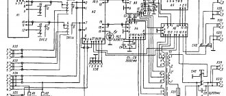
The final circuit of the Amfiton-U-002-v2021 amplifier.
Red "X" means "delete". A crossed out value of an element means a change (the new value is indicated in green next to it). Blue color indicates added elements.
Unfortunately, there was no diagram of the arrangement of elements on the Amphiton-U-002 UM PP. I had to spend an hour sketching:
Step-by-step instructions for modification.
15.1 Replace power supply capacitors (see point 10).
15.2 Rebuild the IST (on VT3) to a value of 2.5 mA. Replace transistor VT1 (KT315) with a zener diode KS168A. It is necessary to select a pair of zener diodes with a voltage of 6.0 V at a current of 0.25 mA. For a value of 6V, resistors R7 = 2.2 kOhm were calculated. Replace R7 with 2.2 kOhm. The voltage across resistor R7 d.b. about 5.4 V.
15.3 Replace R15 and R16 (to 470 Ohm and 300 Ohm respectively). The voltage across resistor R17=120 Ohm is about 0.83 V.
15.4 Dismantle R5 (here it’s up to your taste: desolder it or just cut it out with side cutters: I personally did it).
Turn on the PA, check the bias voltage at the output of each channel: d.b. within 25 mV.
If the voltage is slightly higher (I got -60mV in the PC), then R4 should be adjusted. If the offset is “minus”, then reduce R4, if it is “plus”, then increase it.
A change of 100 ohms gives a change in output of about 50 mV. I had to put 1.1 kOhm, resulting in -7mV in the PC.
I didn’t adjust anything in the LC: -16mV.
15.5 Remove R13. Replace R11 with 2 kOhm.
That. We got an OOS divider of 1:9 so that the gain was 10 (i.e. 20 dB). Optional: replace R1 with 100 Ohm.
15.6 Turn on the PA, make sure that everything is normal on each channel. Naturally, turn off the mind.
15.7 Now the most “intimate” part of the PA is frequency correction. Remove C4, C6, C8, C9. These are the capacitors that did not allow the amplifier to breathe freely:
Replace R5 with 100 Ohm (there will be a 15 nF capacitor in series with it).
15.8 Installation of capacitors 10..12pF (red body) and 15pF (blue body) on the PCB:
15.9 Installing a 15 nF capacitor on the PCB:
15.10 It is recommended to start the PA after changing the frequency correction using a specialized power supply (black box in the photo) and/or lamp protection.
A specialized power supply is a bipolar +-30V power supply with a power limit of 30 W (there is a specially designed weak transformer and capacitors of only 2200 uF; and one 0.65A SVP for each polarity).
Each channel is turned on one by one. Using an oscilloscope, we check the output for absence of generation and other troubles. If everything is fine, you can turn off the safety devices and continue to use the native power supply of the PA.
15.11 Optional: replace the input and output connectors. 15.12 Optional: replace the AC protection board against constant voltage at the output of the PA (in my PA this has already been done a long time ago). 15.13 Optional: disable overcurrent protection (remove VD4 and VD5) 15.14 Final touch: replacing the UM power supply fuses with SVP 2.5A 60V:
16
. Measurements. PC slew rate 15V/µs:
LC slew rate 15V/µs:
Harmonic distortion without load: Harmonic distortion with 4 ohm load:
For comparison, before the rework it was:
All! You can tighten the screws on the covers, connect the speakers and listen.
17.
The audition took place on the Heco speaker system. The sub was not used because The low frequencies are somewhat distracting. The sound of the Amfiton-U-002-2021 amplifier is very similar to its recently modified brother, the Amfiton-U-101M.
The situation with low frequencies, naturally, has improved (due to the reduction in gain from 20 to 10, the damping coefficient has increased). Well, replacing the power supply capacitors did not go without a trace. A memory shot at the end of listening:
18.
Results, conclusions: - the slew rate is increased three times (up to 15 V/µs) - the harmonic coefficient could not be reduced, but the 2nd harmonic was dominant, which is not typical for transistor amplifiers - the Multisim 10 simulation program does an excellent job of calculating the slew rate SR - calculation of Kg (THD), as a rule, bypass: the actual values of Kg in 90% of cases turn out worse than the calculated ones - calculation of the frequency response and phase response of amplifiers is quite accurate - calculation of the frequency response and phase response of passive filters and active filters on op-amps - ideal ©
Perhaps it would be possible to obtain even better parameters. The recipe is simple: all semiconductors from the PCB are dismantled, a reverse circuit is assembled using 2n5551, 2n5401, etc. But this will require complete disassembly of the amplifier.
The most interesting scheme for modification is
... in the amplifier "Lorta-002"
The reason is circled with a “marker”. But the 5th or 6th UM in the house is probably too much. ))
I express my gratitude to V. Shushurin for the circuits, the potential of which could not be revealed in serial products. Special thanks to N. Sukhov for his articles and ideas that suggest the right path in development.
Happy amplifier launches to everyone!
Additional options
The Amphiton-002 amplifier has some features that make its use more comfortable. These include the ability to connect multiple sound sources. On the front panel there is a “Selector” type control that allows you to select the playback device. There are also two operating modes: mono and stereo. There is a button for correcting the sound picture when listening to sound from vinyl records and a button for equalizing low frequencies at minimum volume. In general, many consider this particular amplifier to be the best of the Amphitons. And the point here is not at all about his class. It's just made very high quality and has many useful options.
"Amfiton-002" is capable of delivering excellent, deep bass. Many people use this device as a bass amplifier. And they are partly right. However, the amplifier does not cope well with other frequencies. To fine-tune the sound image, there are special controls that will help you adjust the timbre and all the main frequencies. This amplifier can be considered one of the most functional among those that were produced in the Soviet Union before and after. Now let's move on to another section of our material.
Amplifier Specifications
So, let's take a closer look at Amphiton-002. The characteristics of the device allow it to be used in tandem with Hi-End speaker systems. Judge for yourself. Rated power is 25 watts. Maximum short-term power is 100 Watts. The frequency range varies from 40 to 16,000 hertz. This is a completely acceptable result. Especially when you consider the “age” of the amplifier. The reproduced frequency range is between 20 and 25,000 Hz. This already makes the device stand out from similar Soviet-made amplifiers.
"Amfiton U-002 Stereo" also boasts decent low-frequency amplification, ideal high-frequency reproduction, and excellent mid-frequency reproduction. And it doesn’t matter at all what source the sound comes from. There is also no hiss at high volumes, which is typical of many entry-level Soviet amplifiers. Five-pin sockets are used as connectors for connecting equipment. Connecting a computer or CD player will not be difficult, since there are many adapters available at retail.
Amplifier repair
Like all Soviet equipment, this device is perfectly repairable. If any component fails, replacing it will not be difficult. You just need to correctly determine what exactly is broken. And then everything will go like clockwork. However, in order to repair the amplifier yourself, you need to have at least a little understanding of radio engineering. Without this, there is no point in even getting into the insides of Amphiton-002. Repair is also simple because finding suitable parts or their analogues is not a problem. Just go to any radio store. Capacitors, windings, wires, transformers - all this is on sale.
However, there is one more feature of the Amphiton-002 repair. The amplifier circuit must be present before your eyes. Without it, it is not possible to understand what the Soviet engineers have contrived. If you do not have time to repair the amplifier, then you can take it to any workshop. They will happily undertake the repair of this unit. And they won’t take it very expensive, because the parts are cheap. And for repairs you only need a regular soldering iron.