I made an SE amplifier on the GU-50 and, as usual, the question arose about the volume control. I didn’t want to install a regular SP, and it would be difficult to attach the remote control (remote control). It is expensive to buy a potentiometer from a well-known company APLS, and our dealers don’t have them. I often saw on the Internet circuits of regulators based on resistive dividers; people call them “Nikitin regulators.” Finally got around to trying it.
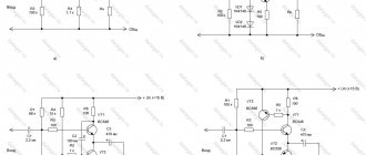
↑ Attenuator circuit
The schemes presented in various sources had an adjustment step of 1 or 2 dB, and a maximum signal attenuation of 63 or 127 dB.
I decided to make an intermediate option with a step of 1.5 dB and an attenuation of 94.5 dB. A resistance of 10 kOhm is not enough for a tube amplifier, so I converted it to 33 kOhm. It turned out to be 6 stages with resistors of the following values.
Various websites offering regulator designers write about the criticality of the resistors used in the divider. It is strongly recommended to use a 0.5% series, or at least 1%. I have enough resistors and I simply selected those closest to the calculated ones, paying special attention to the symmetry between the channels. Example: according to calculations, a resistor of 9.638 kOhm is needed, I selected 9.653 and 9.654 (for 2 channels).
The requirements for the relay are also not poor. I took a relay from an old mini telephone exchange, an Alcatel relay for 24 volts with 2 groups of contacts. Well, they just exist.
How to add loudness pins to a variable resistor?
To add loudness compensation pins, the potentiometer must be disassembled and additional pins must be riveted to the existing holes. The petals for these pins can be borrowed from a faulty potentiometer.
But this operation requires the use of special equipment, ready-made rivets and experience. The fact is that the housings and resistive elements of potentiometers are quite fragile. Therefore, to fasten additional terminals, I recommend using M1.6 or M1.4 screws rather than rivets.
To prevent the screw heads from clinging to the collector, they need to be shortened to 0.5 mm.
The nuts can be secured with varnish or glue.
Return to top to “Table of Contents”
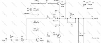
↑ BU diagram
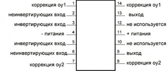
When developing the circuit, I wanted to make the relay control static, without high-frequency circuits. Registers are used for this, and the display circuit has already been used in my previous designs. The microcontroller matched the resources of PIC12F675
.
I wrote the program in assembler from scratch, without other people's inserts. The operation of the device is quite simple, we measure the voltage at the analog inputs (AN0, AN1), and depending on their value, we turn on the necessary relays. At the same time, we listen to the GP3 digital port for the presence of a message from the IR remote control. We expose the data to the GP2 output, and strobe the data through the GP4 and GP5 ports into the required pair of registers. For each bit change, we write 2 bytes sequentially. Chains R25, C8, R28 filter high-frequency noise when writing to registers. Recording time 192 µS.
↑ A little theory
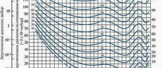
Where did all this come from, these curves and functional dependencies? Apparently it all started from the curve of human hearing depending on changes in signal level. That is, how loud our ears perceive the incoming sound depending on its level. And this dependence is logarithmic: the human ear has a logarithmic (close to logarithmic) dependence of sound perception. That is, our sensation of loudness is proportional to the decimal logarithms taken from the sound power. The ear sensitivity graph is approximately like this:
The dependence of the change in the resistance of a resistor is usually measured from the angle of rotation of the motor of this resistor. And the resistor for a passive volume control (with smooth adjustment) should have an exponential (inverse logarithmic) characteristic.
The exact repetition of this curve is not at all necessary. You just need to be nearby. If you use a regulator with a direct (linear) dependence, the volume increases sharply at the beginning of rotation and remains almost unchanged when the knob moves at the end. Thus, if you take and add the hearing curve and the resistance change curve of the resistor, you will get an even (straight or very close to it) line, and adjustment by ear will be perceived smoothly.
The overall result is a logarithmic volume control—a control that has an inverse logarithmic relationship between the angle of rotation of the knob and the change in volume.
↑ BU design and details
Structurally, the device is divided into two parts. The display unit, on which the controller is installed, is located on the front panel.
Relay module located near the inputs.
Printed circuit boards are made using LUT technology. On the divider board, the top layer of foil is left and used as a screen.
In the design, you can use a relay for a different voltage, respectively, connecting it to a different power supply. The transistors can be replaced with similar ones, but it must be taken into account that the KT972 has a built-in diode. IR23 registers can be 155, 1533, 555 series, imported 74S374 or, if the board is changed, IR8 155 series, etc. A feature of IR23 is its high load capacity. I used the KRT-30 IR receiver. You can use any other brands, the main thing is that the modulation frequency of the remote control matches the frequency of the receiver, otherwise the range of the remote control may be greatly reduced.
power unit
may differ from what is indicated. In my case, the standby voltage of 15V is stabilized at 12V, it is also used to power the display unit, and 24V is taken from the main ultrasonic transformer. The amplifier turn-on relay is designed for 12V and is powered by the standby power supply.
Separately, I will say about the power supply to the divider relay and input selector: it must be well stabilized, so a relay for a higher voltage is better suited (less current consumption).
The input and output selector switch is shown in the diagram as a biscuit switch; you can also use a variable resistor (similar to the volume control).
How to disassemble a variable resistor type SP3-33?
There are two designs of SP3-33 resistors. They differ in the presence of metal rivets and a screen covering the resistive element.
But they are disassembled in the same way, by cutting off rivets or plastic deposits formed after hot flaring. The tool can be used the same as for disassembling slide potentiometers.
To replace lost rivets, when assembling SP3-33 potentiometers, you can use copper or aluminum wire with a diameter of 1.6 mm, the ends of which are bent to the side (item 2). In the place where the plastic was melted, we drill holes with a diameter of 1.6 mm to a depth of 1-2 mm and fuse pieces of wire there using a soldering iron, the ends of which are also bent to the side. But, it is better to use ordinary or hollow rivets with a diameter of 1.6 mm and a length of 3-4 mm (item 1).
You can assemble a slide resistor in the same way.
If several slider potentiometers are arranged in a row and there is not enough room to bend the wire, then the wire can be riveted.
To do this, you need to choose a suitable hammer or give its wedge-shaped part a rounded shape.
Aesthetes can use a special frame.
Return to top to “Table of Contents”
↑ Operation of the regulator
After turning on the power switch, the amplifier is in standby mode, with the indicator showing “—“.
To turn it on, you need to turn the volume knob or change the position of the input switch; the indicator displays the attenuation value in dB “32” (for example, corresponds to the position of the volume control). The anode voltage relay turns on after approximately 70 seconds. Next, we adjust the volume, switch inputs, i.e. we manage as we wish. The following functions are available from the remote control:
0 — power on/off 1 — volume [+] 2 — volume [-] 3 — switching inputs in a ring [+] 4 — switching outputs 5 — switching the indicator mode 6 — switching inputs in a ring [-] 7 — mute button 8 — switching off/on anode 9 – not used
How to disassemble a variable resistor type SP-1, SP-3?
It is even easier to disassemble the potentiometer type SP-1, SP-3. To do this, we unbend the metal tabs that secure the casing to the resistor body.
You will need a special tool to remove the retaining ring. It can be made from some small pliers or pliers.
After removing the retaining ring, disassembling the potentiometer is easy.
This is what the parts from which the SP-3 potentiometer is assembled look like.
Return to top to “Table of Contents”
↑ Remote control training
Constant use of the previous design revealed a lack of attachment to a specific remote control, so here I made a learning remote control.
You can use remote controls of popular protocols NEC, RC-6, RC-5. With the device completely turned off, set the volume to maximum attenuation and the switch to position 2/4 (maximum). Turn on the device, within 3 seconds you need to press any key on the remote control. If the remote control is suitable, then “H0” is displayed on the indicator - you are asked to select the first key (from the list above), press it. The unit accepts the code, “H1” is displayed on the indicators, etc. The number is the function number from the list. Unnecessary functions can be blocked by any buttons already in use.
If within 3 seconds after turning on a key on the remote control is not pressed or the remote control does not comply with the protocol, then the device goes into standby mode.
When the amplifier is turned on, the initial settings (volume, inputs, outputs) are taken from the position of the knobs on the front panel. When programming, you can safely press the buttons for 1 second or more (repetition is not processed). If desired, having read the controller’s non-volatile memory data with the programmer, we will see the key codes - the two most significant bits of the device code.
How to disassemble a slider variable resistor?
To disassemble slider potentiometers of the SP-3-23 type, it is enough to cut off the heads of two rivets.
This can be done using a chisel sharpened in a certain way.
Then you need to remove the remaining rivets using a drift.
This picture demonstrates the procedure for complete disassembly, which may be necessary to install additional loudspeaker terminals.
And these are all the parts from which the slide potentiometer is assembled.
Return to top to “Table of Contents”
↑ Simplified version
For those who only need a volume control, here is a simplified diagram.
You can program two remote control buttons without an indicator. We switch SA1 to the open state, the volume control to the maximum attenuation position, turn on the power, and press any button on the remote control for 3 seconds. If the remote control is suitable, then when SA1 is switched, all relays remain turned off (maximum attenuation). We program the buttons themselves, press any unused button 1 time, and then 1 - volume [+] 2 - volume [-] Now turn off the device, or press any key on the remote control 7 times. All buttons are programmed.
↑ Results
I was completely satisfied with the operation of the regulator; the volume is adjusted smoothly and in small steps. In the headphones you can hear the relay switching (a faint rustling sound only at the moment of regulation), in the speakers the regulation is practically inaudible. The indicator shows the attenuation in decibels, which is very practical. The measurements showed a completely linear frequency response, no distortion of the signal shape, the attenuation error over the entire control range does not exceed 0.25 dB, and the asymmetry across the channels is extremely small. The device was successful.
How to clean a variable resistor?
There is a persistent misconception in which the source of rustling, crackling and potentiometer breaks is a violation of contact between the slider and the resistive element.
I hasten to report that in many cases, contact failure occurs between the current collector and the metal track of the commutator. This happens especially often when, when assembling the potentiometer, no protective lubricant was applied to the collector track, and the material of the track or its coating is susceptible to oxidation. The picture shows the collector before and after cleaning.
Therefore, in addition to cleaning the resistive element, traces of oxidation should be removed from the collector track and the contact part of the current collector using an eraser.
After this, the tracks of the collector and the resistive element are lubricated with technical Vaseline CIATIM or the like, and the potentiometer is assembled in the reverse order of disassembly.
But some types of potentiometers, such as SP3-4, cannot be completely disassembled. In such cases, we proceed as follows. Remove the cover. If the current collector is lubricated with Vaseline, wash the potentiometer in gasoline and dry it.
We cut out a strip about 5mm wide from “Nulevka” sandpaper (more about what “Nulevka” is >>>). We push it between the commutator track and one of the current collectors, so that the abrasive side faces the commutator. Rotate the potentiometer shaft so that the sandpaper remains stationary. Then we repeat the procedure by inserting sandpaper between the commutator and the second current collector. We blow or wash the potentiometer.
We lubricate the track of the collector and the resistive element with technical petroleum jelly using a wooden spatula, which can be made from a match.
The video shows the process of disassembling, cleaning, lubricating and assembling different types of potentiometers used in household radio equipment.
Return to top to “Table of Contents”
