SE or single-ended circuits are amplifiers in which the signal is amplified by one amplifying element (tube, transistor) in series at each stage. These systems operate in pure Class A and are valued by many audiophiles for their good microdynamics and precision in detail presentation. Simplicity is also an advantage. The disadvantages of these circuits are: low energy efficiency (Class A), low gain, slightly higher distortion. We present here a prototype of such an amplifier.
It is supposed to be a simple and cheap system that can be built with minimal electronics experience. Typically the most expensive part of a tube amplifier is the speaker transformers, power transformers, and tubes. Therefore, to reduce costs, we suggest using acoustic transformers from an old tube TV (you will need two). In such a TV you will also find radio tubes, more powerful resistors, and some high-voltage capacitors will also come in handy.
The tubes needed to create this amplifier can also be obtained by disassembling an old radio. Network transformers can be wound or purchased. Of course, this is not a Hi-End amplifier, but a simple amplifier for beginners, but the sound will already be noticeably different from “silicon”. Although the sound quality in tube amplifiers is highly dependent on the speaker transformers. The small transformers offered for assembly, used in tube TVs, do not have very good frequency parameters. A really good transformer is large, heavy and quite expensive.
List of elements
Amplifier
- R1, R1A – 1 kOhm,
- R2, R2A – 470 kOhm,
- R3, R3A – 150 kOhm,
- R4, R4A – 1-1.5 kOhm,
- R5, R5A – 150-200 kOhm
- R6, R6A – 470 kOhm,
- R7, R7A – 1 kOhm,
- R8 – 500-1000 Ohm, adjust the grid current so that it does not exceed 5 mA,
- R9, R9A – 120-180 Ohm, select to obtain the required cathode current,
- R10, R10A – 5-20 kOhm,
- R11 – 10-20 kOhm,
- P – 2×47 kOhm / logarithmic,
- C1, C1A – 100 µF / 16 V,
- C2, C2A – 100-220 nF / 250 V,
- C3 – 100 nF / 400 V,
- C4 – 47 µF / 400 V,
- C5, C5A – 100 µF / 25 V,
- C7 – 33-100 pF, choose so that it does not cut off high frequencies and the oscilloscope signal is correct,
- C6, C6A – solder about 1nF/250V directly to the speaker transformer outputs.
power unit
- R101 – 400-1000 Ohm / 5 W,
- R102, – 3-5 kOhm / 1 W,
- R103 – 270 kOhm / 0.5 W,
- R106 – 0.8-1.5 kOhm so that the LED shines brightly enough,
- R104, R105 – 100 Ohm,
- C101 – 100 nF / 400 V, C102, C103, C104, 105 – 100 µF / 400 V,
- C106, C107 – 47 µF / 400 V,
- M1 – diode bridge rectifier 5-10 A / 600 V,
- power transformer 220 V / 250 V – 0.15 A, 6.3 V – 2.5 A.
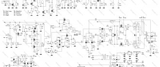
The scheme is very simple. The figure shows one channel, the other is identical. The input signal is fed through potentiometer P to low-power triodes (L1), operating in a common-cathode circuit. After amplification, the pentode (L2) is fed through capacitor C2. The loudspeaker transformer (its anode winding) is the load for this lamp. The secondary windings of the transformer allow you to power a speaker or headphones.
The amplifier is surrounded by a negative feedback loop, which reduces distortion and broadens the frequency response. However, this is done at the cost of amplification. Feedback is taken from the output of the transformer speaker and is supplied through resistor R10 to the cathode of the first lamp (L1). Capacitor C7 is used for possible phase correction. Capacitors C3, C4 and resistor R11 form a filter to prevent excitation of the amplifier. A similar role is played by resistors R1 and R7 in the lamp grid circuits.
The L2 radio tube can operate in two modes - pentode and triode. Pentode mode is more powerful, with more distortion. Triode mode is less efficient but has less distortion. Changing the operating mode can be done with resistor R8. In triode mode it should have a small value - usually 100 Ohms. If we want to use the pentode mode to operate the amplifier, we connect R8 as shown in the diagram. You can give a higher value, but so that the current flowing through grid 2 is slightly less than 5 mA. Typically the resistor value is 500-1000 ohms.
To connect loudspeakers, you need a transformer that will change the high voltage in the anode circuit to match the impedance of the speakers or headphones. Popular and easy-to-get transformers from an old tube TV are ideal for this purpose. Naturally you will need two, one per channel.
You can experiment with other lamps, instead of 6P14P use more powerful pentodes (for example 6L6 or others), but remember that this requires changing the supply voltage, the power transformer must also have more power. The values of the elements that determine the operating point of the lamp must also be selected accordingly, and the AC transformers must be adapted to the type of lamp. Circuits of such amplifiers can be easily found on our website.
Schematic diagram
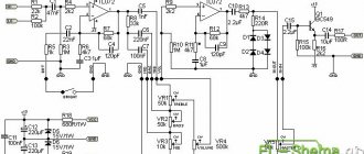
The pre-amplifier circuit is shown in the figure:
(Click to enlarge)
One of the four inputs is selected by slide switch S1. The diagram does not indicate the values of resistors R1, R5, R9, R13; they are selected based on the required input sensitivity. The input impedance of the amplifier is 50 kOhm. The relatively low input impedance of the lamp is reduced even further due to negative feedback. Therefore, the input resistance of the circuit is determined mainly by the value of resistor R19.
The lamp's own gain is 50, due to feedback it is reduced to 6.5. The inherent distortion of the lamp due to the negative feedback decreased to 0.03% with a signal amplitude of 1V at the output.
Please note that the lamp's own noise does not decrease due to feedback, but in the selected modes it turns out to be very low: the signal to noise ratio exceeds 90 dB.
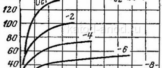
An RC circuit is added to the feedback circuit to compensate for the loss of low-frequency gain that typically occurs due to insufficient listening room volume. As stated at the beginning of the article, the rise is 3 dB for frequencies below 100 Hz.
If you do not need such a function, elements C11-C12, D1, K1-K2 can not be installed, and resistors R31-R32 can be replaced with jumpers.
Setting the volume control at the preamplifier output is optimal for minimizing the signal-to-noise ratio. In this case, the risk of putting the cascade into limiting mode is eliminated, since to obtain a maximum output signal amplitude of 30 V, an input signal with an amplitude of 4.6 V is needed! (a rare source is able to give it away)
Amplifier power supply
The power supply is also not complicated. The anode voltage is rectified using a bridge and filtered by an RC filter consisting of resistors R101-R102 and capacitors C101-C107. Resistor R108 discharges high-voltage capacitors after turning off the power.
Resistors R105, R104 balance the filament voltage to ground, so the network noise heard in the speakers should be minimal. Resistor R101 gets quite hot, so for better heat dissipation it can be placed on a small radiator, or two can be connected at once - in series or in parallel (by selecting the resistance of individual resistors accordingly). This power supply provides power to both ULF channels simultaneously.
After switching on, the amplifier must warm up for several minutes so that the currents flowing through the lamps stabilize. Resistors R101 and R102 in the power supply, as well as R9 and R9A on the lamps, will heat up to a high temperature, this is normal. However, if there is a smell of scorched varnish in the air and we see that the paint on one of the resistors changes color, then the resistor has too little reserve. In this case, it should be replaced with one of the same rating, but with more power. After a longer period of operation, we again check the supply voltage and the voltage drop across the cathode resistors of the lamps. We correct the anode currents of lamp L2 (L2A).
Pre-amplifier power supply.
The filament voltage of the lamps is supplied to the contacts on the printed circuit board. Thanks to this, it is possible to connect the filaments in parallel, then a voltage of 6-6.3 V will be required with a current consumption of 400 mA. Or you can connect the filaments of both lamps in series, then you will need a voltage of 12V with a current of 200mA...
Based on the anode voltage, the amplifier consumes 7 mA. If you recalculate the value of resistor R33, you can power the amplifier with a voltage from 300 to 320 V DC.
To enable low frequency equalization, +24 VDC is required to drive two 12 V relays.
ULF printed circuit boards
You can assemble the ULF by surface mounting, or you can assemble it on printed circuit boards. The drawing of boards with lamps shows the method of connection with other elements of the amplifier (potentiometer, transformers). All connections are made using twisted pair, that is, a pair of tightly twisted wires. This should eliminate or at least reduce the induced noise in the wires.
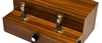
It is based on a metal chassis. Behind the speaker transformers is a toroidal power transformer housed in a metal can that reduces line noise generated by the transformer.
The amplifier really plays warmly and somehow differently, it has a greater depth of sound, more volume. Although it only provides 2W of power, the sound is perfect for a small room!
Attention! Electronic devices are usually powered by 220 V. Mains voltage is dangerous, so use well-thought-out design solutions to avoid exposing yourself and other users to electric shock. Tube devices also contain high voltages. Make any adjustments only when the power source is turned off and after the high voltage capacitors have discharged. Lamps and some resistors reach high temperatures.
Due to their high input impedance, lamps are very sensitive to external interference. Therefore, use shielded cables. The metal connected to the amplifier body ground will protect the amplifier from picking up external noise.
- ULF CLASS D WITH RADIO TUBE
- HOMEMADE ULF PUSH-PULL
- TUBE FOR HOME AUDIO SYSTEM
- PREAMP FOR RECORD PLAYER
Pre-amplifier design
Printed circuit boards
All elements of the circuit, including input connectors, relays, flip switch, and volume control are mounted on printed circuit boards. (Fig. 5). All connections are made on connectors, with the exception of filament circuits, which are soldered directly into the board.
Main board
The circuit board has no special features; all circuit elements are mounted on it. First, 7 1.3 mm contacts are soldered (see photo of the design), then thirteen jumpers. The remaining remaining elements are installed in circuit number order, with the potentiometer and roller switch installed last. The common wire (ground) is connected between the two dual RCA input jacks.
View of the board from the conductor side:
(Click to enlarge)
Arrangement of elements on the board:
(Click to enlarge)
Lamp board
The board is soldered into the main board of the amplifier using 5 mm contacts at an angle of 90 degrees. The board drawing is shown in the figure below:
The arrangement of elements on the lamp board is shown in the figure:
↑ Amplifier and power supply circuit
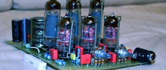
I bought a breadboard and quickly laid out the following circuit on it.
This was probably repeated by every radio amateur who deals with lamps.
The simplest circuit with two lamps. The heart of the power supply was the aforementioned TAN-46. I assembled two 125V windings and got 250V AC. Load capacity 0.118mA. I calculated the anode current of all four lamps based on the maximum value and got 0.1184 mA. Suitable, so all the lamps at once will not consume the maximum current. And if you remember the “Soviet safety margin” of transformers, you can generally sleep peacefully.