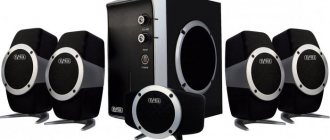
XY is a headphone amplifier
Headphone amplifier designer. I was hoping that the store would send this construction set for review. Not wait. I bought it for my own money. But this is for the best - I assembled the device normally and slowly. The result is in this review.
This designer is also sold on Ali. But there it costs $17 - aliexpress.com/item/Free-Shipping-DIY-HIFI-Fever-Amp-Headphone-Amplifier-Kit-AC15V-High-Quality/32573566932.html. On ebay the price is the same as on banggood. Searched for "DIY HIFI Fever Amp Headphone Amplifier Kit". I have not seen it assembled.
Characteristics:
Supply voltage: AC 15V Maximum power: 300mW Headphone impedance: 32 - 600 ohm 15Hz-100KHz SNR: >100dB Distortion: <0.02% Channel separation: >70dB
It came in a standard black soft bag. Equipment:
Instructions in Chinese:
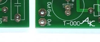
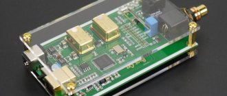
Double-sided printed circuit board - made with high quality, the tracks are routed normally:
Board size - 86 mm x 125 mm. The board says XY HiFi ver 1.1. There are no holes for installation in the case. It is supposed to be installed in a case with side “rails” under the board. But they can be drilled into the corners of the board - the tracks will not be damaged. In this case, it is better to install the board into the case on nylon legs. The part numbers on the board are not labeled. Subscribed to instructions. There is no schematic diagram of the device. On the product page there is a link to a diagram drawn by the buyer Vlad-1357
. If he is reading this page, thank him very much.
I redrew it on the computer:
Details:
The power supply contains 4007 diodes. There are 4148 diodes in the final transistor stage. Headphone protection circuit against constant output voltage and turn-on delay on the uPC1237 chip. Immediately before assembly, I replaced all capacitors with normal ones - WIMA and Nichicon:
Soldered:
Notes on assembly: 1. I wrote above about replacing all capacitors. I don’t know how it sounds on stock. 2. I highly recommend replacing the NE5532 operational amplifier with OPA2134PA. The cost of such an upgrade is about 200 rubles. The amplifier begins to play cleaner and more pleasantly. 3. Regarding power supply - I tried to power the circuit from two separate windings of a 15 V transformer through diode bridges - I did not notice any measurements in the sound. I returned the original power supply. 4. Blue power LED. It doesn't shine very brightly. You can change it if you wish. 5. The 50 kOhm variable resistor for the volume control seemed normal at first - it didn’t crackle. At zero volume no signal is heard. But then I listened better. The channel balance is off: the right channel is louder than the left. Was replaced by ALPS RK27 A50K (https://mysku.ru/blog/ebay/40146.html). 6. The transformer for power supply used a flooded transformer BVEI 304 2043 (2.6VA 230V 15V/174mA). I bought it offline at the Electronics store. At the gain limit (sine to the input from the generator), such a transformer heats up to 30-40 degrees. It is clear that most likely no one will use the amplifier this way. In normal mode it is slightly warm. 7. Transistors BD139/BD140 were selected in pairs with the same static current transfer coefficient h21e using the “people's transistor tester”. 8. Transistors and power stabilizers hardly heat up. Can not be installed on radiators. 9. The 3.5 mm headphone jack was replaced with a six mm jack. I made a tap for the output from the jack to use the amplifier as a preamplifier if the headphones are disconnected. 10. I threw out the power switch and soldered it with a jumper.
As a load - two 51 Ohm resistors (I have Sennheiser HD595 50 Ohm headphones). We test with a signal generator: Maximum gain - then if we increase the signal amplitude we get clipping:
I temporarily soldered it after the rectifier diodes into the power supply gap with a 0.22 Ohm resistor to measure the quiescent current and max consumption. Turned off the input signal. Quiescent current:
According to Ohm's law, based on the voltage drop across the resistor, we calculate 0.005 V / 0.22 Ohm = 0.022 A Max. consumption. We feed the signal from the generator to the clipping input of the amplifier and get:
The current increases smoothly with increasing amplitude of the input signal. This means the amplifier operates in class B.
According to Ohm's law, based on the voltage drop across the resistor, we calculate 0.018 V / 0.22 Ohm = 0.082 A. In total, the amplifier consumes a maximum of 2 * 0.082 A * 15 V = 2.45 Watts. Some more (a little) protection consumes.
I connected the headphones. I liked the sound. The background is almost inaudible. After placement in the housing, shielding of input-output circuits, ground wiring and connections. the background disappeared towards the body. The amplifier's excitation from the cell phone also disappeared. The sound is high quality, transparent, detailed. Highs, lows and mids are clearly audible. The color of the sound is also not audible. The amplifier starts playing well right away. "Warming up" is not needed. The amplifier is cold during operation. For headphones in the $100-150 range this would be an ideal device. There are no more expensive headphones available.
I placed the design in a case from an old CDROM. Standard solution
Result:
UPDATE link to video where someone assembles this amplifier - www.youtube.com/watch?v=Ti6OSXfvzGg
Audio Operational Amplifier Comparison Test
Everything turned out as if by itself: I was debugging a stand for frequency analysis of my products, achieving a minimum level of distortion. After all, you really want to be able to see behind the noise and distortions of the stand what the device under test brings. During the debugging process, I couldn’t resist and tested all the more or less high-quality Operational Amplifiers (OP-Amps) that were on hand at that time.
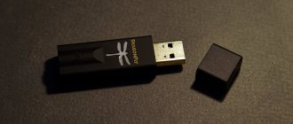
The XMOS board “XK-USB-AUDIO-U8-2C” (it has a CS5340 ADC) was used as an ADC. It also has a DAC, but after comparing the level of interference from this board, and what the AD1955 DAC handkerchief bought on eBay produced (in total, 9 different DACs and sound cards were tested), everything was inexorably resolved in favor of a less pretentious, and at the same time a noticeably less noisy brother from the Middle Kingdom (alas, both of my FluidDACs no longer work for me). The maximum achievable mode for this DAC-ADC combination turned out to be 24-bit 96 KHz. I connected digital audio from the computer to the DAC via a USB→I2S/SPDIF converter on the CM6631A.
The characteristics of operational amplifiers do not always predict the behavior of a given instance in a particular circuit. For the sake of truth, it should be noted that in several very meticulous documents on the so-called “audio op-amps”, there is even a picture of the harmonic distortions introduced by that amplifier (with a sad predominance of higher odd numbers). More often, there is a lonely figure Kg / THD.
There are three dual Operational Amplifiers (O-Amps) on the DAC board. Here is a diagram of one channel from the AD documentation:
In full accordance with the manufacturer's recommendations, two op-amps operate as current-voltage converters ( IV converter ) for a DAC with a current output, the third op-amp reduces the differential signal to a single-phase one. The requirements for them differ: the op-amp in the IV converter must be high-speed and with good load capacity, while the output op-amp ( differential operational amplifier ) is more sensitive to distortion at the input and output.
The Chinese put in good op-amps (from disassembly! but that’s a separate conversation), and they obviously don’t go into much detail, so initially all three op-amps on the DAC board were the same, and the result was far from ideal.
After about two hundred measurements, a picture emerged that was pleasing in its consistency with what I had heard in the past when comparing various op-amps in the JAST-Amp amplifier layout. Then OPA2132 was the best of those tested, OPA2134 and OPA2604 were liked a little less, they were about equal. At the same time, I remember I was surprised by the quite decent sound of the TL072. But OPA2111 played completely unconvincingly. I didn’t try op-amps with bipolars at the input to JAST-Amp at that time.
The measurement results are presented in the table. Not all combinations were measured; therefore, there were empty cells left.
Just in case: link to the table in google docs.
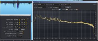
The table shows the instantaneous values of the harmonic distortion coefficient (Kg / THD) in%, the fundamental frequency is 1 KHz, in square brackets is also the THD value, but measured at a frequency of 1100 Hz. In reality, the value of Kg that the program calculates is constantly changing within several digits of the least significant digit. The best operational amplifiers , or rather the measurement results for the best I/V and differential combinations, are highlighted in green in the table. Completely unusable - red.
The most interesting thing can be seen in the spectrograms: what harmonics each op-amp generates, as well as their various combinations. The purpose of this measurement was to obtain the minimum level of all harmonics for the measuring stand. However, for a DAC that will be listened to, it is quite possible to allow the predominance of the second harmonic - this will be imperceptible to the ear, or will add a little softness to the sound. But the predominance of the third harmonic (and higher odd ones) immediately raises concerns about whether such an op-amp is worth installing in the audio path at all...
Spectrometer screenshots are available for each measurement. I invite you to OU meditation