Amplifier for electret microphone with AGC
When studying the connection diagrams for electret microphones [1], their uniformity is deeply surprising. The connection point between the microphone and the load resistor is connected to the amplifier itself through a coupling capacitor (Fig. 1) in 100% of the studied circuits.
Rice. 1
There may be other connection schemes, but the author has not seen them. At the same time, anyone who has been closely and long associated with audio reproduction will probably not strongly object to the fact that any capacitor in the path of the audio signal is an undesirable component. This is especially true for electrolytic capacitors, which are inevitably used in the case of a sufficiently low input resistance of the amplifier stage.
An approximate study of the operating modes of electret microphones [2] showed that, firstly, they are current sources and, secondly, the maximum amplitude of their output signal is observed when the voltage drops across the microphone and the load resistor are the same.
Let's consider one of the well-known [3] circuits of a microphone amplifier with an AGC system made using an op-amp (Fig. 2).
Rice. 2
The circuit consists of a non-inverting amplifier itself based on op-amp DA1, the non-inverting input of which receives an artificial midpoint from the divider R3R4, as well as the input signal through the isolation capacitor C2; controlled divider of the OOS signal (resistor R5, capacitor C1 and channel resistance of the field-effect transistor with PN junction VT1); output amplified signal detector (capacitors C3, C4 and diodes VD1, VD2). The detected output signal of negative polarity controls the conductivity of the VT1 channel, increasing it, thereby reducing the gain of the op-amp.
Considering the presence of a constant component of the divider formed by the electret microphone and its load resistor, we can conclude that the components C2R3R4 are completely unnecessary. The role of R4 is perfectly performed by the microphone itself, and R3 is its load resistor. Capacitor C2 is generally superfluous, as a class.
The result was the diagram shown in Fig. 3.
Rice. 3
The R3C1 RC filter provides additional filtering of the electret microphone supply voltage. In principle, it is optional (optional), but actually quite useful. The value of resistor R1 is selected such that at the point of its connection with the microphone there is approximately half the supply voltage. Resistors R4R6 linearize the transfer function of the controlled resistor on the field-effect transistor VT1.
Instead of resistor R5, a double T-shaped filter (on the right) can be included in the OOS circuit, raising the frequency band corresponding to the voice range. Its frequency response is shown on a Bode plotter from Multisim measuring instruments (below)
Naturally, any theoretical rants can be taken into account only if they are confirmed by practice. Therefore, the diagram shown in Fig. 3, was studied on a prototype.
Available micropower op-amps based on TLC271 and TL081 MOS transistors were used. The results were identical. In principle, any “sound” op amp can be used as an op amp (which absolutely does NOT include the LM358/324 and their clones!!!). The electret microphone used for these experiments was type J60. Repeating the experiments with other microphones was considered inappropriate in terms of time. Signal diagrams from the op-amp output were recorded with a RIGOL DS1052E digital oscilloscope. The “test phrase” spoken into the microphone at approximately the same volume was: “One-two-three-four-five, the bunny went out for a walk.” Of course, for the purity of the experiment, it would be desirable to use a recording played back through a speaker, but what happened is what happened.
First, a circuit without AGC was investigated. The detector and field-effect transistor were not connected, and a 10 kOhm resistor was connected from the lower terminal of capacitor C2 to the common negative bus. Thus, the gain was 11. The output signal for fast (10 ms/div) and slow (100 ms/div) sweeps at a distance of 20 cm from the mouth to the microphone are shown, respectively, in Fig. 4.
Rice. 4
I was surprised by the signal range (peak-to-peak), which was more than 2 V. This means that the signal from the microphone was about 200 mV!!!
Next, instead of a 10 kOhm resistor, a field-effect transistor KP303Zh was connected with an initial drain current of 0.85 mA and a cut-off voltage of 0.7 V. Its gate was connected to the negative bus, which ensured the minimum resistance of its channel and, accordingly, maximum gain. The output signal of such a circuit is shown in Fig. 5.
Rice. 5
As you can see, the signal from the microphone is excessively amplified, right up to clipping, which indicates the applicability of a field-effect transistor with such a small initial drain current with an OOS resistor resistance of about 100 kOhm.
Next, the complete circuit was studied, with all shown in Fig. 3 components. The output signals when pronouncing the “test phrase” from a distance of 20 and 60 cm, respectively (with slow scan) are shown in Fig. 6, and from a distance of 60 (with fast scan) - in Fig. 7.
Rice. 6
Rice. 7
As can be seen from these diagrams, the signal swing was about 4 V with a satisfactory shape, which is quite sufficient for ordinary applications. Unfortunately, the initial “surge” of amplitude (while the AGC system had not yet activated) could not be registered. The gopher was not visible, but he was present by ear...
Finally, two more field-effect transistors with a higher initial drain current and cutoff voltage were studied (respectively, another KP303Zh with an initial drain current of 1.2 mA and a cutoff voltage of 0.9 V, as well as KP303V with an initial drain current of 2.6 mA and cut-off voltage 1.2 V). The output signal with the first of them at a distance to the microphone of 20 cm (with slow scan) is shown in Fig. 8, and the output signals with the second at a distance to the microphone of 10 cm and 40 cm (with slow scan) are shown in Fig. 9.
Rice. 8
Rice. 9
In the first case, the signal swing was almost 5 V, and in the second - almost 7 V!
From these experimentally obtained data it is clear that for practical purposes it is desirable to use field-effect transistors with the lowest possible cutoff voltage. The initial drain current does not significantly affect the stabilized amplitude of the output signal for a given resistance of the OOS resistor.
Finally, the microphone “muting” mode was tested by short-circuiting the inverting and non-inverting inputs of the op-amp. There were no audible “clicks” with this method of muting.
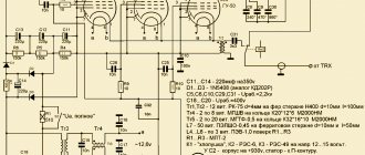
For a “snack” - a circuit similar in function, made with transistors (maybe someone will like it): Fig. 10. True, it was not mocked up “live”, it was only simulated in Multisim. It showed almost the same results as the op-amp circuit.
Rice. 10
Field effect transistor Q1 with resistor R1 is a model of an electret microphone. The value of the load resistor R2 selects half the supply voltage at the point where it connects to the microphone. The value of resistor R4 selects the equality of the collector currents Q2 and Q3. Field-effect transistor Q4 with resistor R5 is a parametric current generator for the differential stage on transistors Q2 and Q3. A similar role is played by transistor Q7 with resistor R9. for transistor Q6. In principle, these current generators can be replaced with ordinary resistors, but with them the amplifier parameters are by definition better. Finally, the variable resistor in the OOS circuit on transistor Q5 and the output signal detector are the same as in the op-amp circuit.
Conclusions:
- Another amplifier for an electret microphone is presented to the court, which does not pretend to be exclusive, but is somewhat simpler than the known ones. Due to the elimination of one coupling capacitor in the audio signal path, it is of higher quality by definition.
- Considering the fairly high gain provided by this amplifier, the op-amps for it, in order to provide sufficient bandwidth, must have a cutoff frequency of at least 5...10 MHz.
- This amplifier without an AGC system can be used for highly sensitive amplification of signals from an electret microphone.
Literature:
- https://forum.cxem.net/uploads/monthly_04_2011/post-57852-0-96201600-1301791430.gif2.
- https://forum.cxem.net/index.php?/blogs/entry/429-dancing-with-a-tambourine-around-an-electret-microphone/
- https://nauchebe.net/2014/06/vysokochastotnye-vxodnye-usiliteli-i-aru-dlya-novichkov-v-radiodele/
Tags:
- AGC
Notes from a programmer
Some time ago we learned how to make an AGC based on a photoresistor. The scheme works, but has drawbacks. Firstly, not every radio amateur keeps photoresistors in stock, which, other things being equal, reduces repeatability. Secondly, the scheme requires manipulations with heat shrinks and hot glue. This makes it difficult to use in mass production. It turns out that there is a scheme that is devoid of these shortcomings and works no worse.
The circuit first came across to me in the article “A Simple 20M QRP SSB Transceiver”, written by Robert Seiler, HB9TSE, and published in SPRAT magazine for the summer of 2006. The article was included in the book “The Low Power SPRAT Book”. Idea credited to David Forsman, WA7JHZ:
You can download the full model for LTspice here.
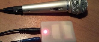
Before us is a copy of the ULF circuit from the article about the superheterodyne receiver, only five components that implement AGC were added at the bottom. The higher the signal level coming from the ULF to the speaker, the higher the voltage at the gate of the BS170 (datasheet [PDF]). The dependence can be adjusted using potentiometer R8-R9. When Vgs(th) is reached, the transistor opens and current begins to flow from drain to source. As a result, the level of the signal entering the ULF drops, and, as a result, the level of the output signal drops. The values of C8 and R10 determine the response time of the AGC.
In fact, BS170 here acts as a variable resistor controlled by the gate voltage:
The dependence of Vds on Id for currents of the order of 10-100 mA is almost linear, like that of a resistor. The higher the Vgs, the steeper the graph. This means a lower Vds/Id ratio, that is, lower resistance.
Instead of BS170, 2N7000 can be used. In his datasheet [PDF] you will find a graph similar to the one above. See also comments in the full version of the model for LTspice.
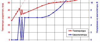
The circuit was tested in a homemade SSB transceiver. During the experiments, the following graphs were obtained:
Along the OX axis is the signal level supplied to the transceiver (S9 = -73 dBm), along the OY axis is the signal swing at the ULF output at maximum volume. The red and blue graphs correspond to AGC turned off and on, respectively. A signal with a swing of 1 Vpp is a good, legible signal, at which you already want to turn down the volume a little. 2 Vpp peak-to-peak is very loud, but still without any negative effects on the ears. Thus, the circuit successfully protects the operator from stunning.
The operation of the circuit depends on the supply voltage. If you plan to use the transceiver in the field and power it from a battery, you will need to add a voltage regulator. LM7805 is quite suitable. The circuit is also sensitive to temperature. When the BS170 heats up, the output swing becomes ~30% lower, and when cooled, it becomes ~30% higher. From a practical point of view, this is not a problem unless you plan to use the circuit in extreme conditions. It would also be a good idea to compensate for the loss of sensitivity. To do this, you need to add a gain stage of 10-20 dB in the receiving path.
Addition: Continuing the topic about AGC and the differences between AGC in LF and AGC in HF, see the article AYN/A: analog CW QRP transceiver for 20/40 meters.
Tags: Wireless, Ham Radio, Electronics.