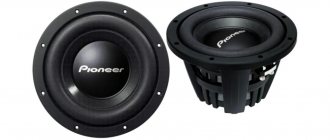
The mid-frequency electrodynamic loudspeaker was manufactured at the Riga Radio Plant named after. A.S. Popova . This allowed 3 versions of 4 Ohms , 8 Ohms and 16 Ohms .
Purpose : for use in closed and phase-inverted acoustic systems of the first and second complexity groups as a mid-frequency link for indoor work.
Description of the 15GD-11 design:
The loudspeaker head is of electrodynamic type, round, with an unshielded magnetic circuit. The basket is made of die-cast aluminum alloy.
Modification of 15 GD-11A (20 GDS-4-8) and 10 GD-35 (10 GDV-2-16)
A way to refine this speaker that allows you to noticeably improve its sound in just one day. It should be noted that the results of the modification of 35 speakers were tested only by ear, by assessing the sound quality by experts.
It is known that with a linear frequency response, the nominal and noise power of the loudspeaker are largely determined by the power and sensitivity of the midrange head. In addition, the mid frequencies reproduced by this head, as the most informationally significant, significantly affect the sound quality of any speaker.
In the 35 AS loudspeaker, 15 GD-11A (new name 20 GDS-4-8) is used as a midrange driver. The disadvantages include strong diffuser sounds or so-called structural sounds. These distortions are generated by parasitic vibrations of the radiating surfaces of the loudspeaker. Moreover, they are very insignificant when reproducing a sinusoidal signal and increase significantly when reproducing a real musical signal, giving the sound an unpleasant “cardboard” character. Such distortion is especially noticeable when playing stereo programs. Moreover, they occur in all traditional loudspeaker heads, not excluding 4 GD-53 (new name 5 GDSH-5-4). However, in the powerful 15 GD-11A, these distortions are especially intolerable due to the high sound pressure, at which parasitic vibrations sharply increase, a large share of which falls on the dust cap of the 15 GD-11A head and its diffuser.
Unfortunately, there is practically nothing to replace the 15 GD-11A head with, and there remains only one way to improve the sound of the 35AC - modifying the midrange head, which was done by the author. Experiments with head 15 GD-11A showed that its structural overtones can be significantly reduced by creating on its basis a combined, cone-dome type of head with mating shells, in other words, by installing an additional radiating dome on top of the dust cap. The head modified in this way is interesting in that both shells (cap and dome) are strongly damped by the volume of air located between them, and this makes it possible to obtain a dome of acceptable rigidity without the use of superhard materials. After installing the dome, deformations of the cap are reduced and the radiation of vibrations directly into the air is eliminated. The rigid edge of the dome also stabilizes the center of the diffuser, preventing the occurrence of noticeable deformations in the area of the diffuser that is most significant for influencing the sound quality of the head. Deformations in its peripheral areas are not reduced, but are well masked by the radiation of the dome, which has a high efficiency. In general, the entire moving head system operates in a mode closer to a piston. The technology for converting the 15 GD-11A head is quite simple, and even a novice radio amateur can perform it if the recommendations given below are strictly followed.
Half of a celluloid table tennis ball was used as a dome. First, the ball should be sawed or cut with a scalpel exactly along the line of the weld. which is clearly visible in the light. The edges of the ball halves obtained in this way must be smoothed using fine sandpaper. There is no need to remove the thickening of the weld seam from the inside; it is enough to just slightly scrape off the beads with a knife so that the dome can be easily put on the dust cap without effort or play.
The resulting blanks are fixed on mandrels (it is convenient to use 373 batteries) with rubber glue with the convex side up. To remove irregularities, the outer surface of the balls should be cleaned with fine sandpaper and then try not to touch it with your hands. Then you need to dilute 0.5 cm3 of epoxy resin with double the amount of hardener and coat the balls with the resulting composition in a very thin, even layer. All excess resin should be removed with a clean, lint-free cloth.
After fifteen minutes, you should inspect the surface of the balls and, if necessary, wipe them again (but not dry) with a cloth. If the glue layer is sufficiently even, you can proceed to further finishing the surface of the balls with graphite powder, which can be obtained by rubbing the lead of a simple medium-hard pencil on fine sandpaper. The powder is generously applied to the surface of the balls, then the layer of powder is leveled with a finger and polished with a cotton swab, adding powder all the time. The movements should be light and sliding so that the thin film of resin applied to the ball does not move. This coating provides the necessary rigidity of the dome with its light weight, so it is important to take precautions here. If you rub the dome blanks too hard, so that the ball is visible through the graphite, then unwanted “celluloid” sounds may appear, but if the coating layer is too thick, the dome will turn out heavy and the sound will be dull.
When the workpieces acquire a strong metallic shine, the work can be considered complete. All that remains is to glue the completely dried domes along the edges on top of the dust caps of the heads with hard, preferably nitrocellulose glue (“Super Cement”, “AGO”, etc.). The seam must be sealed.
The baskets were additionally covered with foam rings made from 10x27x355 mm blanks, the ends of which were glued end-to-end with Moment glue. The midrange head boxes are completely filled with cotton wool. It is useful to listen to the sound of the converted heads in the midrange, cutting off the lower and higher frequencies with an equalizer. If you bring your ear closer to the head itself, you can easily hear the slightest interference; in the same way, you can select the optimal damping by ear.
Despite its simplicity, the modification noticeably changed the properties of the head, immediately improving a whole range of its parameters. First of all, the new head practically does not change the timbre color of the reproduced signal, i.e. brings the sound closer to the sound of the original program. Such a head confidently reproduces the hardest real signal with an amplitude of over 12 V, while an unmodified head simply fails in such cases: wheezing and rustling sounds appear, which makes the signal illegible.
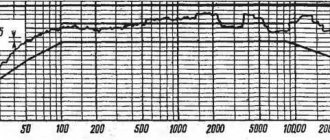
As expected, the frequency band expanded to 6500 Hz. those. the main drawback of the 15 GD-11A head has disappeared.
Thanks to the shape and small size of the main emitter, the directivity characteristics of the head have become noticeably better. The sharp dips in the frequency response in sound pressure when shifted from the acoustic axis have completely disappeared, and within an angle of approximately ±30° the decline is not audible at all. The wide directivity characteristic of the emitter not only greatly expanded the listening area. but it also made it possible to improve the sound in the center of the zone, i.e. it created the effect of a uniform sound field.
It is interesting that despite the increase in moving mass and strong damping. head recoil has not decreased. and increased by approximately 3 dB. This phenomenon, which at first glance seems paradoxical, is easily explained by the high efficiency of the hard emitter and the reduction of acoustic losses “in the cellulose”.
It is appropriate to note a significant drawback of the 35 AC-1 and its various modifications, which their owners are usually unaware of. Before the alteration, there was a chronic deficit in the speakers (in this case, tones above 500 - 1000 Hz), which could not be corrected by any frequency response correction (this is true for both 35 AC-1 and 35 AC-212 (S-90) , 35 AC-013, etc.), which was often explained by age-related degradation of listeners’ hearing. After the rework, “everything went away.”
Finally, a parameter that cannot be determined numerically, but is very noticeable, has improved: sound cohesion at “high” frequencies. This factor, in particular, also reduces the binding of sound to the loudspeaker. The sound source seems to be blurred, without worsening the localization of the apparent sound sources.
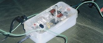
Of course, to get all the listed benefits of the speaker system. You should first “cure” the head 10 GD-35 (10 GDV-2-16), and this is even easier to do. It is enough to bypass it with a notch filter tuned to a frequency of 3000 Hz. It is a high-Q series LC circuit. The capacitance of the circuit capacitors is 6.6 μF (MBGO and MBM with a permissible deviation from the nominal value of ±10%), the inductance of the coil is 0.43 mH, its winding contains 150 turns of PEV-1 wire with a core diameter of 0.8 mm, wound on a frame diameter 22 and length 22 mm with a cheek diameter of 44 mm. Using these data, it is possible to assemble a circuit without an LC meter, since it is not the exact value that is important, but the “capture” of the resonant frequency, which has a certain spread. Ideally, it is better to adjust the circuit to a specific head, although this is not strictly necessary. The circuit is mounted on plywood measuring 75x30 mm, which is glued through a layer of rubber with “Moment” glue to the wall of the speaker. One terminal, for example from capacitors, is soldered to the wire connecting the attenuator to the head, the other to the common wire.
As a result of the described modification, it was possible to get rid of not only overtones and rattling at any volume, but also the characteristic “hissing”, usually considered an integral property of the 10 GD-35 head. Now the head works no worse, but better than heads 6 GD-13 (6 GDV-4-8), especially at loudness peaks, primarily due to greater power and broadband, i.e. less influence of the suspension system.
The results of the examination fully confirmed the correctness of the theoretical premises underlying modernization.
During the examination with the participation of professional classical musicians, excerpts of musical works of various genres performed on different instruments were used, according to standard methods. The signal source was phonograms recorded on high-quality DMM records, reproduced by a Corvette-128 pickup head and a high-linear field-effect transistor amplifier with a rated power of 90 W.
All experts (tests were carried out by each separately) first of all noted the high naturalness of the sound - in principle, a self-sufficient criterion for sound quality.
Purity and clarity of sound, without noticeable overtones, are maintained over a wide power range, up to maximum. During normal listening, the speaker has a significant margin of up to 20 - 30 dB for peak signal values, which sound very light and bright. This leads to an important conclusion. It's no secret that 35 speakers are considered systems with insufficient dynamic range (unfortunately, replacing the midrange head limits it even more). Moreover, even the nominal range cannot be satisfactorily implemented due to the avalanche-like growth of distortion. The latter circumstance creates the impression of amplitude limitation. The proposed upgrade can be considered as expanding the dynamic range to a level that satisfies any home listening conditions.
The rated power of the converted speaker is at least 53 W, which corresponds to a sound pressure of 103 dB. In maximum power mode, this figure is 105 - 106 dB, which is not the limit. The redesigned midrange head, when supplied with maximum power, sounds better than the original one at nominal, i.e. The power characteristics of the speakers, provided they are of high quality, are primarily limited by the power of the filter resistors and, to a lesser extent, by the steepness of the filters. In other words, with a simple improvement you can get speakers with a maximum power of up to 130 W and a sound pressure of 107 dB, which corresponds to the international level for prestigious systems. In this case, the power and distortion of the speakers will be determined only by the woofer head; the distortion of the midrange and high-frequency path will still not exceed the nominal ones.
Mobile system 15GD-11:
- voice coil wound with PETV-1 wire with a diameter of 0.16 mm, two-layer winding, total number of turns 68, in the first layer 35 turns, in the second 33. Ohmic resistance 3.4 Ohm (±0.3 Ohm). The coil frame is made of A6-M-0.05x24 grade foil and EN-70 paper. Inner diameter 25.4 mm, outer diameter 26.35 mm.
- conical diffuser made of impregnated paper pulp.
- spherical cap made of impregnated paper pulp.
- toroidal suspension made of rubberized fabric.
- centering washer made of impregnated fabric.
Modernization of AC 35AC-012 (S-90). (Part 3)
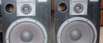
An alternative to the speaker 15GD-11A. It is known that the weakest link in the 35AS-012 speaker system is the 15GD-11A (20GDS-1-8) dynamic head. The results of many years of practice in refining this head in order to improve its sound quality, unfortunately, do not satisfy all lovers of good sound. Many refer to the opinion that the 15GD-11A speakers need to be replaced with heads of similar dimensions and installation dimensions[25], for example, 4GDSH-1 (4GD-8E), 5GDSH-5-4 (4GD-53), 6GDSH-5 -4, 30GDS-1-8 - fig. 19. However, it is impossible to simply replace the GG with another one, due to the fact that in the acoustic system all the heads, LF, MF, HF, are coordinated with each other based on their individual parameters.
A
b
V
G
Rice. 19. Diffuser dynamic loudspeakers, overall and installation dimensions: a – 4GDSH-1; b – 5GDSH-5-4; 6GDSH-5-4/8; 30GDS-1-8
It is believed that the amplitude-frequency characteristic of the GG is one of the main indicators for assessing sound quality. The heads 4GDSH-1, 5GDSH-5-4, 6GDSH-5-4/8 are noticeably superior to 15GD-11A in this parameter. The second factor influencing sound quality is the acoustic quality factor of the head. For 15GD-11A this figure is several times higher than for 4GDSH-1, 5GDSH-5-4, 6GDSH-5-4, and the higher the quality factor of the moving system, the higher the distortion in the region of the main resonance frequency, which negatively affects the sound quality . The main characteristics of diffuser dynamic loudspeakers are shown in Table 4.
Table 4. Main characteristics of cone dynamic loudspeakers
| Head name according to GOST 9010-78 | According to OST 4. 383.001-85. Modern analogue | Maximum noise (certificate) / maximum long-term / maximum short-term power, W | Rated (operating) power, W | Nominal resistance, Ohm | Frequency range, Hz | Full quality factor | Frequency response unevenness, dB | Standard sound pressure, Pa | Main resonance frequency, Hz | Characteristic sensitivity level, dB/mW | Overall dimensions (in plan), mm | Height, mm | Weight, kg |
| 4GD-8E | 4GDSH-1-4 | 4/6/10 | 4 | 125…7100 | 1,3 | 14 | 0,3 | 120 | 93,5 | 125x125 | 49 | 0,6 | |
| 4GD-53 | 5GDSH-5-4 | 5/8/15 | 1 | 4 | 100…12000 | 1,3 | 14 | 0,28 | 150 | 92,5 | 125x125 | 49 | 0,6 |
| 6GDSH-5-4/8 | 6/15/45 | 4 | 4/8 | 100…12000 | 1,4 | 14 | 140 | 92 | 125x125 | 45,5 | 0,29 | ||
| 30GDS-1-8 | 30/50/100 | 8 | 500…6300 | 8 | 0,26 | 250 | 92 | 125x125 | 70 | 1,7 |
The main disadvantage of 4GDSH-1, 5GDSH-5-4, 6GDSH-5-4 is its relatively low power. But the efficiency of these heads is much higher than that of 15GD-11A. The efficiency of a dynamic cone loudspeaker is the ratio of the radiated acoustic power to the supplied electrical power. The efficiency of a loudspeaker directly depends on the standard sound pressure or characteristic sensitivity, which is uniquely related to acoustic power. In other words, in order to create sound pressure of the same level on the heads 4GDSH-1, 5GDSH-5-4, 6GDSH-5-4/8, much less power should be supplied than to 15GD-11A. A change in the energy parameter, the supplied power, twice corresponds to a change in level by 3 dB, and four times - by 6 dB. The 75GDN-1-4 low-frequency head has a maximum noise power of 75 W, a characteristic sensitivity level of 85 dB/m (minus 1 dB for filter losses) and a nominal impedance of 4 Ohms. The 6GDSH-5-8 mid-frequency head has a maximum noise power of 6 W, a characteristic sensitivity level of 92 dB/m and a nominal impedance of 8 Ohms. The difference in sensitivity in relation to the woofer head is 7 dB - 2.24 times in sound pressure and 5 times (2.342 = 5) in power. Thus, the maximum noise power of the mid-frequency head, reduced to the sensitivity of the low-frequency head, is 6 W x 5 = 30 W. When operating in the frequency band from 500 Hz to 5000 Hz, the midrange head accounts for only 41.5% of the power, i.e. - 31 W, which almost meets the requirements. If we also take into account the difference in the nominal resistances of the GG, 8 Ohms and 4 Ohms, then when connecting these heads to a common source, the sound pressure must be reduced by √(8/4) = 1.41 times, i.e. by 3 dB, and take it equal to 89 – 85 = 4 dB. To equalize the sensitivity of the mid-frequency head with respect to the low-frequency one, the circuit is supplemented with a divider (R"1 and R2" in the diagram in Fig. 20) [15]. It is also necessary to adjust the compensator (R2, C11) for changes in the electrical resistance module when switched on through the separating filter of the 6GDSH-5-8 loudspeaker head. To do this, Capacitor C11 is set to 8 μF. The 30GDS-1-8 head is also connected using the same scheme, as the most suitable replacement for the 15GD-11A speaker, while installing a C11 capacitor with a nominal value of 2 μF.
Rice. 20. Electrical circuit diagram of the modernized AS 35AS-012 (S-90) using a dynamic head 6GDSH-5-8
When installing a 5GDSH-5-4 (6GDSH-5-4) speaker with a nominal resistance of 4 Ohms, the circuit is supplemented with just one element - a resistor R»1 with a nominal value of 4.3 Ohms and a power of 7...10 W - fig. 21. This will ensure both the necessary equalization of the sound pressure of the emitters and the resistance. Let me remind you that the bandpass filter of the acoustic system 35AC-012 (S – 90) is designed to connect a midrange head with a nominal impedance of 8 Ohms.
Rice. 21. Electrical circuit diagram of the modernized AS 35AS-012 (S-90) using dynamic heads 5GDSH-5-4
It is even easier to implement the connection of the 4GDSH-1 head (by excluding elements L'1 and C'2 from the circuit). The formation of a frequency response decline of 12 dB per octave occurs as a result of the interaction of the transfer characteristic of a first-order filter with a slope slope of 6 dB per octave (L4) and the natural decline in the frequency response of the 4GDSH-1 head, Fig. 22, near the interface strip [1]. Therefore, there is no need to use a 3rd order low pass filter in a bandpass filter. A 1st order filter on L4 is quite sufficient to provide the necessary attenuation. The HF head 10Gd-35, in this case, is turned on in antiphase to the midrange - fig. 23.
Rice. 22. Frequency response of sound pressure of dynamic head 4GDSH-1
Rice. 23. Electrical circuit diagram of the modernized AS 35AS-012 (S-90) using a dynamic head 4GDSH-1 (4GD-8E)
The minimum permissible power PR dissipated by resistor R»1 is calculated by the formula: PR = Pd(R/Rd), where Pd is the rated power of the speaker; R – resistance of resistor R»1; Rd – nominal speaker impedance. The actual power of the resistor is selected to be 1.5...2 times greater than the calculated one. When installing resistors, you should not make it difficult to remove heat from them [26].
Sources (continued, beginning in the first and second parts)
25. Zyzyuk A. About the repair of acoustic systems and loudspeakers - RadioAmator No. 6, 2003.
26. https://baseacoustica.ru/izgotovlenie/31-izgotovlenie-kolonok/161-metodika-sozdanija-akusticheskih-sistem-chast-4.html
Author: Vladimir Marchenko, Uman, Ukraine