Many people have sometimes had to wonder what exactly the power means, which is given in one form or another in the passports of acoustic systems and sound reinforcement equipment. There are surprisingly few materials on this topic on the Internet and in printed publications, and there are also few clear answers to questions. I'll try to somehow reduce the number of white spots in this area. Some more precise descriptions of definitions arose in my dialogue, when trying to better explain their meaning to my interlocutor.
The variety of standards used to measure amplifier output power and speaker power can be confusing for anyone. Here is a block amplifier from a reputable company with 35 W per channel, and here is a cheap music center with a 1000 W sticker. Such a comparison will clearly cause confusion among a potential buyer. It's time to turn to standards...
9.1 Calculation of the sound power component for each segment of the measuring surface
The sound power component in each frequency band for each segment of the measuring surface is calculated using the formula
(11)
where P i
is the sound power component for segment
i
;
- normal component of sound intensity on the measuring surface, taking into account the sign, at point i
;
Si
is the area of segment
i
.
If the value of the level of the normal component of sound intensity is measured, then it is calculated using the formula
(12)
where I
0 = 10-12 W/m2;
— level of the normal component of sound intensity for segment i
;
sign (+) or (-) corresponds to the sign.
Sound pressure
Sound waves travel through the air in the form of pressure fluctuations. Our ears perceive pressure fluctuations as sound. Sound pressure is measured in pascals (Pa).
The lowest sound pressure that the human ear perceives, 2*10-5 Pa, is the threshold of hearing. The strongest sound pressure that the ear can endure (pain threshold) is 20 Pa, and this is considered the upper limit of audibility. The large numerical difference, measured in Pa, between the hearing threshold and the pain threshold creates inconvenience in the calculation. Therefore, a logarithmic scale is used, which is based on the ratio of the actual sound pressure level to the hearing threshold. This scale uses the decibel (dB) as its unit of measurement, with 0 dB representing the hearing threshold and 120 dB representing the pain threshold.
Sound pressure decreases with increasing distance from the sound source and depends on the acoustic characteristics of the room and the location of the sound source.
Subtraction
The graph is based on the difference in dB between the overall sound level and the already known sound level.
The dB value that must be subtracted from the total sound level is obtained on the y scale. Rice.
6. Logarithmic Subtraction The human ear has varying degrees of sensitivity to sounds of different frequencies. This means that sounds with high and low frequencies of the same power will be recognized as two different sound levels. Simply put, we hear high-frequency sounds better than low-frequency sounds.
Sound pressure level calculation
Using the coefficients described above, it is now possible to calculate the sound pressure level if the sound power level is known. The sound pressure level can be calculated using a formula that includes all these factors, but this equation can also be reproduced in graph form.
Calculation of the sound pressure level according to the graph begins with the distance to the sound source (g) and, taking into account the directivity coefficient (Q), we obtain the difference between the sound power level and the sound pressure level for the equivalent absorption area of a given room (A). We add this difference value to the already known sound power level and obtain the sound pressure level (see also p. 539).
Rice. 3. Approximate estimate of sound pressure level
Adjacent is the space where the noise level from the source dominates the overall noise level in the room. The reverberant space will be dominated by reflected sound. And it is impossible to determine the original source of the sound.
With direct propagation, sound weakens with increasing distance, while reflected sound is approximately the same in all parts of the room.
Rice.
4. Direct and reflected sound. Reverberation time is the time during which the sound level decreases by 60 dB. This is similar to the echo effect that occurs in a quiet room after turning off a powerful sound source. If the reverberation time is calculated accurately enough, then the equivalent absorption area of the room can be calculated using the same formula.
A - filter
Hearing sensitivity also depends on the strength of sound.
To compensate for uneven sound perception, adjustments, so-called filters, are applied to the octave frequency bands. For sound pressure levels below 55 dB, an A-filter is used. For levels between 55 and 85 dB there is a B-filter, and for levels above 85 dB there is a C-filter. Rice.
7. Alignment with A-, B- or C-filters The A-filter is most often used in ventilation, applying an adjustment to each octave frequency band (see Table 2). Therefore, the dB values obtained with the A-filter adjustment are denoted as dB(A).
In addition to filters, there are also other ways to compensate for imperfections in the ear's perception. The graph with NR curves (Noise Rating) shows the sound pressure and frequency of sound, which is perceived equally by the human ear. For example, 43 dB at 4000 Hz is just as dangerous as 65 dB at 125 Hz.
Noise reduction is achieved in two ways: absorption or reflection of sound.
Sound power
Article from the website of the magazine "Avtozvuk"...in fact, we have reason to believe that there is no greater confusion in the minds of the public than that associated with the simple and tasty word “power”.
Power, who is it?
“I have 200 W speakers and a 4 x 50 radio. Will they play together?” Yes they will, they will, don’t worry so much. But it will be even better if you still understand what is meant by both power and watts. “Power,” according to the school definition, is work produced per unit of time; for our purposes, the definition is almost useless. It’s more convenient for us in a different way, albeit unusual: power is the amount of energy converted into the form we need in the same unit of time. It’s always about transformation, energy doesn’t go anywhere, it’s such a habit. An amplifier (even in a radio) receives ready-to-use electrical energy in the form of direct current from the vehicle's on-board network and converts it into electrical energy, but in the form of alternating current, representing a sound signal. All? No, about half, the rest goes into heat given off to the air by small radiators on the back of the radio or large ones “all over the body” of a separate, external amplifier.
The speaker (albeit pretending to be a “speaker”) receives electrical energy in the form of alternating current and converts it into mechanical energy, now in the form of the long-awaited sound vibrations. All? How can I say... Not really. The efficiency of the speaker (since we went the school route: the ratio of the produced sound power to the received electrical power) almost never exceeds 0.5%. Where does the other 99.5% go? And there, in the heat, in general, any device created by the human mind (as well as the will of the Almighty) produces heat plus something else. From the point of view of energy conversion, the speaker is 99 percent identical to a soldering iron. And the remaining half a percent contains everything: bass, treble, detail, and brilliant musicians. It's a shame? Yes, but somehow they couldn’t come up with anything better.
And here it is, the main difference between the power of the amplifier and the power of the speaker: the amplifier can be considered to produce it. And the speaker consumes, without producing in exchange, as we just found out, almost nothing.
And when we talk about the power of an amplifier, we are talking about what IT GIVES. And when talking about the power of the speaker, it’s about what HE TAKES.
How much does one give and how much does the other take? In order of arrival:
How much power does the amplifier provide?
Here's the amplifier. Don't care about the one in the radio for now, then you'll feel the difference. What is its power? Yes, whatever, it all depends on what the signal level is at the input, roughly speaking, what position the volume control is in. The output power may be 1 W, maybe 10, maybe 50, maybe... Wait, there must be a limit. Of course, but we didn’t ask what the MAXIMUM power is. And everyone has their own maximum. It is determined by the highest AC voltage the amplifier can create at its output when a load is connected to the output, in the form of a speaker with some kind of resistance. The output power is determined simply: as the value of this voltage squared and divided by the load resistance. We connected a voltmeter and a load to the output, applied alternating voltage to the input, for convenience of measuring power - at any one frequency, and look. The output is 2V when a 4 ohm load is connected to it. With such measurements, of course, it is not the acoustics that are connected to the output, but its equivalent in the form of a resistor, otherwise your ears will wither. We built and divided and got: the output power is exactly 1 W. There is a slight catch here due to the fact that we are talking about alternating voltage, the magnitude of which can be measured in different ways. The most commonly used scale is the root mean square value scale. In Russian this word is long, so the English abbreviation RMS (root mean square) was adopted, meaning the same thing. In order not to go into details, it is enough to remember: for a sinusoid, the RMS voltage value is 1.41 times less than the amplitude voltage, that is, the root of two. The power indicated in watts RMS is that obtained when the voltage was taken into account in RMS, which is logical. And if we take the voltage amplitude, then the power, firstly, will be called peak, and secondly, it will become exactly twice as much as RMS.
The signal at the output of a conventional amplifier with a 12-volt power supply, as it appears on the oscilloscope screen. The horizontal axis is time, the vertical axis is voltage. Under no circumstances
A sine wave representing a pure tone of a single frequency cannot fall below zero or exceed the limit set by the supply voltage. Actually, this is the output signal of a regular home amplifier, the amplitude of which is set at the desired level, for example.
Let's return to the amplifier. One watt is not serious, we add it at the input. How long will the output voltage rise and what will stop it? Will stop it limiting the signal. The amplifier is powered by a constant voltage, and what appears as alternating voltage at its output cannot be greater in amplitude than the supply voltage. There's no more there. And if we observe the signal at the output, then at some point the tops of the previously graceful wave will be cut off, where the half-wave wanted to go through the upper limit, the supply voltage. And she broke down. We roll back the signal at the input until the limitation disappears, and look at the signal range. It is slightly less than the full supply voltage because something is lost in the amplifier's output stages. If the amplifier is powered (as in the notorious “radio tape recorder”) from the car’s on-board network, then the lower half-wave will come close to the zero mark, and the upper half-wave will come close to the 12 V level. What happens? The amplitude, we assume, is 6 V in each direction, we raise and divide and get the fabulous figure of 4.5 W. Check it out if you're not too lazy. It turns out that, according to all science, this is the maximum power value at the output of a radio powered by 12 V? And that’s how it was twenty years ago. Fortunately, a solution was recently found that made it possible, if not to reach the formidable 4 x 50, then at least to get away from the mournful 2 x 4.5. This is a bridge connection of amplifiers, now used in all automobile head units.
With bridge connection, two amplifiers operate for one load, turned on in such a way that the swing of the sine wave at the output doubles. According to the method already communicated to you to calculate the output power, it will be four times more than 4.5 W, because the voltage is squared, therefore - 18 Watt. This is approximately the maximum output power of all head units we have ever tested.
(in each of the four channels, of course).
Where do the famous 4 x 40 W come from, which then turned into 4 x 45, 4 x 50 and so on? What is this, pure lies? Somehow it does not fit with the image of eminent and more than respectable manufacturers of equipment, but these numbers adorn the front panels of all brands: Alpine, Blaupunkt, Clarion and further in order of the Latin alphabet. After all, when it comes to individual amplifiers from the same companies, everything becomes fair and correct; there have been enough opportunities to be convinced over the years. There are two tricks here, the first is technical, and only the second is marketing. The technical trick is that modern “heads” use amplifiers of the so-called “H class”; there is a special circuit that can provide the output stages with an increased supply voltage for a short time. There is a capacitor and, while everything is quiet, it is charging. And during loudness peaks, it turns out to be connected in series with the power supply of the output stage, and the peak skips through without distortion, without touching the 12 V ceiling with the top of its head. But this is if the signal level peak is very short, for example, the first moment of hitting a drum. Then, of course, the energy supply dries up, but the job has already been done, even two things: indeed, for a brief moment, the maximum power has become much greater than possible with continuous operation, and secondly, the opportunity has arisen to mention it. Without focusing too much on the conditions under which the maximum output power became so. To the credit of respectable companies (see alphabetical list above), it must be said: often in the technical specifications table on the last page of the instructions, continuous power is given, indicating that this is in watts RMS, and indicating what the supply voltage was, as a rule , 14.4 V, because in this case the “ceiling” for the output sinusoid rises, and then exactly 18 - 20 W per channel appear in this line, cases of entering the third ten are rare.
Why aren't they written on the front panel? Consider this a tradition, like oil prices in dollars per barrel, and gold prices per troy ounce. Moreover, as we found out, formally they have the right. Now quickly answer this security question: when was the last time you saw a car speaker that stated LESS than 18 Watts? Therefore, any talk about “selecting” acoustics for the radio according to power makes no sense.
“But how,” you may ask, “did my neighbor in the garage’s 100-watt “mugs” wheeze and burn out?” And this, my dears, happened not because the head unit had a lot of power, but because there was little MAXIMUM power.
Where does the power end?
Everyone sees, but few people pay attention: where the maximum output power is indicated in troy ounces seriously, and not for beauty (for example, on the last page of the instructions), next to it is the value of the nonlinear distortion coefficient corresponding to the given value. We abbreviate this in k.n.i., but in English instructions it will look like THD and some number with a percent sign. Let's remember (or find out) what nonlinear distortions are. They are sometimes called harmonic (THD and stands for Total Harmonic Distortion), which is more correct. The essence of the matter: when the amplifier works ideally, the output signal will differ from the input signal only in amplitude, and in direct proportion. Let's add coke. The output voltage increased by a little over a volt, when suddenly a whole fence of harmonics grew on the spectrogram, which means that the output signal came dangerously close to the maximum possible amplitude. In terms of amplitude, the harmonics seem to be small (the upper scale is greatly stretched vertically), and in total they add up to a small total: less than half a percent. But: this fence was not in the sound before, but now it is. Let’s add one more thing - and here we are: distortions in the shape have become clearly visible on the sine wave, exactly the ones we expected - you can’t jump higher than the power supply. And the output signal has become monstrous, in real life we will hear, in addition to the pure tone of 250 Hz, a lot of new things: both 500 and (especially) 750 Hz, and further to the most impossible frequencies, the consolation that they are all multiples of 250 Hz is rather weak, for hearing it is either a creaking or wheezing, depending on the fundamental frequency. Now the question is: What is the maximum output power? If there was still very little distortion, then it will be 13.5 W. RMS, as you now understand, having seen what the output voltage is indicated. If there is half a percent, then it will be almost 19 watts. And if we agree with 10%, we get a fabulous value for such amplifiers of 23 W. But it’s better to disagree: do you see what lies behind this inconspicuous figure?
The result of our analysis is paradoxical at first glance: on the one hand, the amplifier has only one maximum achievable output power, depending on the supply voltage and load resistance. But at the same time, you can specify it in any way you like; the question is what level of distortion is considered acceptable. Traditionally, for really powerful, external amplifiers, the maximum power value is indicated at a rms equal to 1%. For head units, manufacturers prefer 10%, for reasons that no longer require comment.
And yet, why?
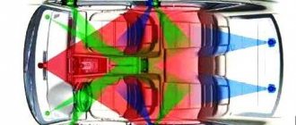
Why, with such, in general, pitiful values of the maximum power of the head unit amplifiers, the “200-watt” 6 x 9 attached to them begin to wheeze, or even burn? Why wheezing, you have already seen: wheezing is the harmonics that appear at the output of the amplifier when it is overloaded. The man thinks that his powerful radio tape recorder has overloaded the speaker, but in fact, the “mug” that they gave him plays, thinking with his mug brains that this is how it should be. Why do they burn if they have such power - like pellets to an elephant? Let's take another look at the results of previous experiments with distortions, and then even continue them. I drew something there: conditional curves showing which part of the frequency spectrum falls on the low-frequency head (actually the “burdock”), and which part falls on the block of high-frequency heads in its center. Naturally, this fully applies to any multi-band acoustics, and we don’t have anything else. Something is playing, and there is a powerful component with a frequency of 250 Hz. The tweeter is still on vacation: in the blue field depicting its operating range, there is almost no signal, and rightly so, this is not its frequency. When the distortion reaches half a percent, something already appears, but so far it’s okay, the amplitudes are small, and most of them fall into the area where the tweeter filter is already starting to cut off what is unnecessary. At 10% it’s no longer good: the tweeter is supposed to be completely at rest, and a bunch of harmonics fall on it, and even with a level higher than the content of the upper frequencies in a normal phonogram. Let's go further, to the limit: we'll twist the input signal so that after cutting off the tops of the half-waves, a meek sinusoid will turn into an almost rectangular signal, in which the harmonics are forty percent of the main signal. This is where the squeaker is most likely destroyed. But we have the same amplifier, and the frequency is still “non-squeaker”. With some natural talent, such a signal can also spoil the midbass. Rectangular pulses carry much more energy to the output than a sine wave, and the electrical power that goes to the speaker will be more than 50 W. Let's imagine a 50-watt soldering iron, then remember that the speaker is 99.5% a soldering iron, and the fate of the voice coil, made, unlike the soldering iron winding, not from nichrome, mica and asbestos, but from much more delicate materials, will cease look cloudless.
Does all this mean that you don’t have to look at the power of the acoustics at all? Not really. You just need to look a little differently.
| But this is a real amplifier, similar to those used in head units. From the point of view of the magnitude of the output signal, such amplifiers assembled using a bridge circuit are equivalent to an amplifier with a bipolar power supply, in our case ±15 V. The upper part of the screen belongs to the spectrum analyzer. Interpreting his testimony is not difficult, it can even be fascinating. The horizontal axis is now the frequency, and the vertical axis is the output signal level at this frequency. As you can see, the main thing at the output is an amplified signal with a frequency of 250 Hz applied to the input. But not only. Each “hairpin” is a harmonic of the fundamental frequency, the Second harmonic is at a frequency of 500 Hz, the third is at 750 and so on. There is not much “and so on” here: the distortion level is very low. A spectrum analyzer is an extremely sensitive thing; you can see, for example, a small protrusion at a frequency of 50 Hz: this is network interference. And the “grass” between the harmonic columns is the amplifier’s own noise. In addition to the total distortion level (that's what is expressed as a percentage), some information is contained in the level of individual harmonics. Even numbers (with a frequency twice, four times, six times, etc. higher than the main tone) are signs of asymmetric signal distortion, odd numbers, starting from the third, are symmetric. |
| The amplitude of the signal increased by a volt and a few kopecks, the shape did not seem to change by eye, but you can’t test it with a spectrum analyzer: how many nasty things appeared in the output signal at once. And although the nastiness is only 0.4%, it will already be audible; the ear is superior in sensitivity to the best devices. Here you can see that the third harmonic began to grow (at 750 Hz), that is, early signs of symmetrical, above and below, signal limitation appeared. |
| Here you can no longer help but notice that the signal has become limited, trying to jump over the limits set by the power supply. There are many harmonics at the output, and the odd ones predominate (3rd, 5th, etc.), which are famous for being the most unpleasant to the ear. |
| From the previous example of the amplifier operating at a power far from the maximum. Our test signal in real conditions is intended exclusively for a mid-bass speaker; the crossover filter does not allow it to pass through the tweeter (the blue curve, rather conditionally). So far so good: there is nothing on the tweeter other than noise. |
| Already at 0.5% distortion, the tweeter begins to get something, this is not enough to harm it, but, thinking that this is the composer’s intention, the HF head will diligently “voice” the harmonics, introducing completely uninvited details into the sound. |
| At 10% distortion, the tweeter is already working in earnest, and this is at a base frequency of 250 Hz. But it could be 1 kHz, or 2 kHz, also frequencies not for a tweeter, and then the second harmonic would hammer the delicate mylar diaphragm. It would be nice if this were recorded, but it wasn’t: the tweeter works “to wear out” solely due to the uncleanliness of the amplifier. |
| Drop limit: the amplifier is so overloaded that the sine wave has turned into a series of rectangular pulses. This is already dangerous not only for the tweeter: the power contained in such a signal is much greater than in a sine wave of equal amplitude, because square waves are “thicker”. Now the output power is about 50 W, which (minus 0.4 - 0.5%) must be converted into heat by the voice coil. She shouldn't be jealous now. |
That's it, we persuaded. You need to buy an amplifier.
Clearly, without an amplifier there is no life. We begin to choose and, naturally, the first thing we look at is the maximum (we already know what it is) power, what are we fighting for? How to choose it will be a separate and unexpectedly short conversation. But first, let's determine where this power comes from. What makes a separate amplifier such a qualitatively different device compared to the inherited amplification channels built into the head unit? From the previous text it is clear: it’s all about nutrition. The amplifier creates an alternating voltage at the output with a swing, from top to bottom, no greater than the supply voltage of the output stages. For the radio amplifier, this is the voltage on board, 12 V when the car is turned off, about 14 V when running. The main component of the external amplifier is the power supply. It receives a constant voltage from the on-board network, turns it into an alternating voltage of a fairly high frequency (tens of kilohertz), the alternating voltage can already be increased using a transformer, which is what the amplifier’s power supply does, and then, already increased, it is rectified again and supplied to the amplifier itself. To how many volts the voltage was inflated during this activity, at such a height the ceiling of the output voltage swing will pass. What follows is simple arithmetic. Let’s assume that out of 12 V on-board the power supply has created 50. In reality it will be two voltages of different polarities, 25 V each, it’s more convenient. This means that the output voltage swing (in each direction) will be no more than 25 V minus some pennies lost in the transistors. The maximum power output is 25 squared divided by the load resistance. This is according to Ohm's law, it is inexorable. It comes out to a little more than 150 watts. Only this is the peak value, on the RMS scale - exactly half as much, about 75 W. The numbers are quite real, there are plenty of such amplifiers. Can you get more out of this amp? The first stage of “afterburner” in many models will occur by itself, as soon as you start the engine. And when, with the engine running and the generator running, the voltage on board becomes not 12, but 14.4 Volts, the voltage at the output of the power source will increase from 50 to 60 V, the “ceiling” for the output voltage of the amplifier will also rise, and the maximum power will increase to 108 W. Wow, that's a raise, right? Just don’t rejoice too much just yet. Will this make the amplifier play louder? Why is this, exactly? The overall gain, from the signal source to the output, remained the same, it does not depend on the power supply (and if it suddenly did, the component responsible for this would urgently request permanent registration in the trash can), which means it will be as it played. Another thing is that if previously distortion appeared at some volume, when at the peaks of the signal the output voltage tried to jump over the bar set by the power source, now this moment will move to the area of higher volume. How far will it move? Let's figure it out. One and a half decibels. One click of the volume, or even not a single one, it depends on the step of the control.
What have we gained compared to the “past life”, when there was no amplifier at all? There seems to be a lot of watts. And in decibels of the maximum undistorted volume, again, it seems, not very much: 5.4 dB. But this is only “seemingly”, as we will see later; happiness is not just a matter of clicking the volume control. It is still necessary to organize some kind of harmony between the powers. Look, for example, at what power the acoustics have, and select an amplifier based on that, right?
Wrong.
I did this on purpose, for the purpose of provocation. We talked about how you can ruin acoustics with insufficient power in the last issue, now let's try to do it with too much power. It will be much more difficult, I warn you.
Let's return once again to the phrase that I have said (and written) many times on various occasions, the last time in the last issue. Here it is: “And when we talk about the power of an amplifier, we are talking about what IT GIVES. And when we talk about the power of the speaker, it’s about what HE TAKES.” The maximum power of an amplifier is that which it cannot provide more than, because it begins to distort the signal, and that is not what we bought it for. The maximum power of the acoustics, therefore, is the one it cannot take more than, because WHAT? Does the signal also begin to distort? And it begins to do this at once and little by little, not at all like an amplifier; acoustics do not have a hard limit. In ancient times, there was a Soviet standard by which the so-called rated power of speakers was standardized. Special conditions, frequency bands, and so on were stipulated there; in general, the power was considered such that nonlinear distortions did not exceed 10%. The best bass speaker of that time was called 6GD2, the first number is just the rated power. There were 4 more gas engines, 3 gas engines, and so on, and then they adopted the definition of rated power, which no longer depended on distortion, but on survivability, and all these gas engines at once grew fat to 10, 20, 75, and the like. These GOSTs ordered us all to live a long time, and now power is determined differently, and it is very important to understand this in order to treat this indicator with the attitude it deserves.
I’ll ask you to type this in red, if I forget, you can use a pencil yourself, okay?
The power indicated on the acoustics is not the one at which it should work, but the one that destroys it.
Of course, there must be a relationship between the capabilities of acoustics and the resources of the source of this probable destruction, but this is a relationship, not an identity. Imagine: you bought a car with a maximum speed of 200 km/h. And you got tires with a speed rating of T (190 km/h). What, you can't drive? At 191 km/h all four wheels are in tatters? Or, on the contrary, the tires have a Z speed index (240 or more), and you are knocked off your feet when choosing the right car for such tires. Unreal.
Nevertheless, one often hears (and even reads) how acoustics are selected for an amplifier (and vice versa), looking first at the power, and then at everything else.
So let's do this one last time so as not to return to the question. Power numbers on acoustics, without indicating measurement conditions, do not mean anything; this is part of a modern, but deep-rooted tradition.
If the speaker manufacturer is at least relatively correct in the figures he gives, then he can indicate the long-term power, and this is the maximum non-destructive (or minimally destructive, don’t forget about this) power supplied to the speaker for half an hour according to the scheme: a minute works - two resting. At the same time, a noise signal is supplied, passed through a filter that cuts off everything below 40 Hz and everything above 4 kHz, so this has almost nothing to do with the tweeter. Now, if the acoustics survived the most difficult half hour in its life, the used power value is recorded. If it died, it is taken from previous experience with less power. Short-term power is one that will not destroy the speaker (or will destroy it, but at the last moment) after 60 cycles of “yelling for a second and resting for a minute.” All the described procedures involve bringing the acoustic sample under test as close as possible to the edge of the grave, so it is somehow not very reasonable to rely on them as a standard indicator for someone who paid for the acoustics out of their own pocket. The only type of indicator that even slightly resembles the possible real use of its legal property is rated noise power according to the IEC 268-5 standard, when the acoustics must remain alive after 8 hours of continuous operation on the already mentioned noise signal. It is almost never indicated.
The landmarks here should be different; you shouldn’t look for them on boxes with acoustics.
Landmarks, where are you?
Our in-house experts in acoustics tests have repeatedly recommended (when manufacturers completely lost their shame and it was unthinkable to remain silent) to use indicators that at least approximately indicate the range of possible values. For 6-inch component acoustics, the limits of reasonable risk lie somewhere between 40 and 90 W (this is wide, you already need to look at the design features inside), for 5-inch ones it is naturally lower, 30 - 70 W. These are the rated noise power values we consider. You may disagree, but refuting experiments are at your own expense, please.
The numbers, in principle, resemble the common values of the maximum output power of widely used amplifiers, so the simplest, bordering on primitivism, answer to the question of matching the power of the amplifier with the power of the acoustics is already ready: a typical amplifier is suitable for working with typical acoustics. Anyone - with anyone.
In principle, if you don’t want to worry, you can use it. But the answer is too simple to in any way claim to be exhaustive, that’s clear.
Then you need to look at the realities of life. In life, as I have reason to believe, both the amplifier and the acoustics will be used to reproduce music, and not test signals that are only very roughly similar to music. A music signal is not a sine wave or even noise, it is a signal with a large difference between the average value and the peak value. Short-term signal peaks, with rare exceptions, do not threaten the health of the acoustics, which mainly have to resist thermal stress, and the heat generated at the voice coil is a function of the average level of the input signal. I have seen in the documentation of the most serious acoustics manufacturers how, next to the very real (and indicating all the regulatory data) long-term power figures, the values of withstand power at short (say, 10 ms) peaks were given. The numbers sometimes reached hundreds of watts, and this is no longer marketing, this is a fact, even a very powerful one, but a very short burst of signal will not destroy the speaker. But the amplifier has a fundamentally different view of level peaks. If the signal level exceeds the maximum power level even for a millisecond, it will be mercilessly decapitated, that is, it will go further along the wires to the acoustics in a distorted form, compared to the original source. This cannot be allowed. And here it makes sense to look at your musical tastes.
Tastes are not measured.
Why so? You can also try. I ran a number of musical fragments through the computer and chose ones that were quite indicative in terms of the ratio of average (dangerous for acoustics) and peak (which should be feasible for the amplifier) power. The signal level was measured in decibels relative to the maximum recorded on the disk, but for clarity, I recalculated everything as a percentage of the maximum power. The first picture is 60 seconds of “Procession of the Dwarves” (6th track “Let's Test!”). If the system is configured so that the largest peaks of the signal do not exceed the amplifier's output power, then in general the speakers will receive about one and a half percent of this power during this minute. Even in those 12 seconds, when the orchestra is completely relaxed, the thermal load will be no more than half the power.
A minute of activity of the Yamato drummers (remember when they came to Moscow?). The signal level is chosen to easily miss the peak of activity at 21 seconds. As a result, the average power of the entire fragment is less than a percent of the maximum, and its most intense part is one tenth of the maximum.
Third example: “In the Pocket” (Kai Eckhardt, “NAIM Sampler”, track 8). The average power is 13% of the maximum, and turning up the volume in a sincere attempt to ruin the acoustics will mean cutting off numerous peaks caused by the skillful work of the drummer.
Don't listen to audiophile delights? We won't force you. Here is a fragment of the soundtrack of the punk rock band Kurban (Turkish and, by the way, quite interesting). Here, yes, the guys don’t rest on stage, and the average power for a long time is about 40, or even more percent of the maximum. But the guidelines, in principle, remain the same. It’s just that rock music falls into the category of “flawed control,” which is logical.
An attentive reader may be puzzled here: “ Wait a minute, it turns out that we listen to music on one or two, many - ten watts, connected to the acoustics? Why then does it play loudly?
You heard it yourself: it’s loud.” I’ll answer: why shouldn’t she play loudly? After all, you can easily manage decibels (even those who couldn’t before). We take any acoustics from any of our past tests and look at the sensitivity indicator. Well, let's say 87 dB, this is the average typical value. This sound pressure will be created by this acoustics at a distance of 1 m with a power of 1 (one and only) Watt supplied to it. This, by the way, is no longer quiet. In order for this acoustics to create a sound pressure level of 90 dB, standard for control listening in a sound recording, it only needs 2 W. Apply 10 W and get 97 dB. It's quite loud. Moreover, keep in mind that we have at least two such speakers, and they sound not in a quiet room, but in the cabin, where there are much fewer losses, and the reflected sounds come to us. What then, you ask, will the speaker do when those same hundred peak, say, watts come to it? Exactly what it should: briefly, within a fraction of a second, it will scream at 107 dB. Give him these 100 watts continuously, in the form of noise or, worse, a tone, and this scream will be his death cry. And so, everything is under control, don’t worry.
_____________________________________________________________________________
In acoustics, everything is measured differently than in the ordinary world. There are several reasons for this, some explanations can take you to the paradise of science, we will not touch them. Others are amenable to simple interpretations. Or they can simply be taken on faith, whichever is more convenient for you. Human hearing cannot add and subtract. Just multiply and divide. Evolution (or the Creator, take your pick) arranged it this way, as it seems to me, guided by technical expediency. Hearing operates over a huge range of volumes. The sound pressure (measurable, as is known) corresponding to the pain threshold exceeds the sound pressure of the hearing threshold by ten million times (in words, so as not to count zeros). Hearing adapted to this by becoming (by the will of evolution or the Creator) logarithmic. People came up with logarithms later, but they sit in our heads by nature. The logarithmic nature of hearing is that it evaluates the difference in loudness not by how much greater the sound pressure is, but by how many times greater it has become. So (if we now remove all the intermediate chapters of history) a unit of measurement was invented on which absolutely everything in acoustics and electroacoustics is based - the decibel. Who knows everything about this, do not read further, however, I asked about this when I opened this series of publications. I give the rest, no matter how many there are, the opportunity to master operations with decibels in five minutes and subsequently do it easily and gracefully. So: a decibel is a unit that, if added, means “multiply”, and if subtracted, means “divide”. For example: sound pressure is 3 dB higher. This means double. Another 3 dB? Twice more. More by 1 dB is approximately 1.25 times. 10 dB more - ten times. And vice versa: subtract 3 dB from the sound pressure, and this will mean that it has been halved. It is enough to remember a few important values so that from them, like bricks, you can form an idea of what this or that value indicated in decibels means. Here you are:
| Power or sound pressure varies depending on | Voltage varies according to | |
| 1 dB | 1.25 times | 1.13 times, just a penny |
| 3 dB | 2 times | about one and a half times |
| 6 dB | 4 times | 2 times |
| 10 dB | 10 times | about 3 times |
| 12 dB | 16 times | 4 times |
| 20 dB | 100 times | 10 times |
That's all: you meet, for example, somewhere around 18 dB, you estimate that it is 12 + 6, take the “times” for these two terms and multiply. You multiply, that’s the whole trick. In our example, 16 by 4 gives 64. Just pay attention: when comparing sound pressures and powers, you need to take “times” from the left column, and when comparing voltages, say, from the right, this is a trick due to the fact that an increase in voltage, to for example, at the output of the amplifier, doubling the power leads to a fourfold increase in power (the voltage is squared there), and the decibels are the same, there are 6 of them. However, in the future we will mainly operate with powers and sound pressures, so the right column will remain in reserve for now . What does decibel mean to the ear? A difference in volume of 1 dB (this is the case with most head units - one click of an encoder or volume button) is heard only by immediately comparing how it was and how it is now. Conduct an experiment: listen to the sound at a volume of, say, 15 on the display, and then 16, get out of the car for half a minute, and let your friend (or even a friend) cover the display with his palm (or palm), and you determine: there are 15 or 16 ? If at the same time you pass by the cash register less often than five times out of ten (even on the same fragment), it means that your head unit has a volume step of 2 dB, this also occurs. Although there are, of course, talents. 3 dB is perceived as a noticeable change in volume. Not “big”, but simply noticeable. And here comes some bad news that you might have already guessed. The sound pressure created by the acoustics and the power supplied to the acoustics in order to create it live in the same column of our cheat sheet. Consequently, in order to obtain a noticeable change in volume, the supplied power must be doubled. This is what causes all the problems with power. Mainly because of this...
Frequency
The number of vibrations of a sound source per unit time relative to the average value is determined by frequency. Frequency is measured as the number of vibrations per second, with one vibration per second equal to 1 Hertz (Hz). A higher number of vibrations per second, i.e., a higher frequency, produces a higher pitch.
Frequencies are often divided into 8 groups known as geometric mean frequency bands: 63 Hz, 125 Hz, 250 Hz, 500 Hz, 1000 Hz, 2000 Hz, 4000 Hz and 8000 Hz.
The sound pressure level created by a noise source is influenced by the sound power level of the source, the directivity coefficient (1), the distance to the source (2) and the sound absorption characteristics of the room (3).
Comparative scales for calculating digital sound levels
| Interest | Decibels |
| 120 115 110 105 100 | 1.584 1.214 0.828 0.424 0 |
| 95 90 85 80 75 70 65 60 55 50 45 40 35 30 25 20 15 10 5 | -0.446 -0.915 -1.412 -1.938 -2.499 -3.098 -3.742 -4.437 -5.193 -6.021 -6.936 -7.959 -9.119 -10.458 -12.041 -13.979 -16.478 -20 -26.021 |
| Decibels | Interest |
| 1.6 1.5 1.25 1 0.75 0.5 0.25 0 | 120.23 118.85 115.48 112.2 109.02 105.93 102.92 100 |
| -0.25 -0.5 -0.75 -1 -1.25 -1.5 -1.75 -2 -2.25 -2.5 -3 -3.5 -4 -4.5 -5 -5.5 -6 -6.5 -7 -7.5 -8 -8.5 -9 -9.5 -10.5 -11 -11.5 -12 -15 -18 -21 -24 -30 -33 -35 -40 | 97.16 94.41 91.73 89.13 86.6 84.14 81.75 79.43 77.18 74.99 70.79 66.83 63.1 59.57 56.23 53.09 50.12 47.32 44.67 42.17 39.81 37.58 35.48 33.5 29.85 28.18 26.61 25.12 17.78 12.59 8.91 6.31 3.16 2.24 1.78 1 |
In a series of experiments, starting in 1834, E. Weber showed that a new stimulus, in order to differ in sensations from the previous one, must differ from the original one by an amount proportional to the original stimulus.
Thus, a chandelier with 8 light bulbs seems to us as much brighter than a chandelier with 4 light bulbs as a chandelier with 4 light bulbs is brighter than a chandelier with 2 light bulbs. That is, the number of light bulbs should increase by the same number of times, so that it seems to us that the increase in brightness is constant. And vice versa, if the absolute increase in brightness (the difference in brightness “after” and “before”) is constant, then it will seem to us that the absolute increase decreases as the brightness value itself increases. For example, if you add one light bulb to a chandelier of two light bulbs, the apparent increase in brightness will be significant. If we add one light bulb to a chandelier of 12 light bulbs, we will hardly notice an increase in brightness.
We can also say this: the ratio of the minimum increment in the strength of the stimulus that first evokes new sensations to the initial value of the stimulus is a constant value.
In the 20th century, Stevens proved the limitations of the Weber-Fechner law, which is valid only for certain types of sensations.
- dBFs are scale units for the digital representation of an audio signal (digital scale);
dBu is a scale unit for the analog representation of a signal. According to this scale, 0 dBu ALWAYS = 0.775 V;
Converting voltage level to signal power
At work, we often measure radio signal levels at the antenna input of a measuring receiver. And the measuring receiver in its metrological properties is close to a selective voltmeter, and the measured value is calculated in decibel-microvolts ( dBμV ). At the same time, radio measurements often operate on the signal power at the receiving point, often expressed in decibel-milliwatts ( dBm ). Let's count one into the other!
- Let us rewrite the expression connecting power and voltage once again:
- Let us express the voltage from here:
- The standard antenna input impedance is 50 ohms . Let's take the logarithm of the expression for power. If the voltage is in volts, then the power received will be expressed in watts. express a value in dBµV dBV , it is necessary to subtract 120 dB from it. And to dBW to dBm , you should add 30 dB to the value. Indeed, a signal with a level of 70 dBµV ( 3.16 mV ) develops a power of 0.2 µV , or -37 dBm, 50 Ohms
- Obviously, if we add 107 to the power in dBm , we get a voltage level at a load of 50 Ohms, expressed in dBµV . Indeed, a signal with a power level of -80 dBm ( 10 pW of 22 µV , or 27 dBµV at a load of 50 Ohms
UPD: I wrote this page in a very tired state, and then I made a terrible mistake. I'll definitely fix it a few days later!
And for greater happiness, I made an online calculator that converts voltage in decibel-microvolts into power in decibel-milliwatts and vice versa (I know, I know, there are countless of them on the Internet without me! )
3) Equivalent absorption area of the room, Aeqv
The ability of materials to absorb sound is called absorption coefficient a. The absorption coefficient can range from 0 to 1, with a value of 1 representing a completely absorbing surface and a value of 0 representing a completely reflective surface.
The equivalent absorption area of a room is measured in m2 and can be calculated by multiplying the area of the room's surfaces by their respective absorption coefficients.
In many cases, it is easier to use average values to calculate sound absorption in different types of rooms, and then also an estimate of the equivalent absorption area of the room (see Figure 2).
If the absorption coefficients of all surfaces are not known and it is permissible to use the average absorption coefficient, then it can be calculated from the graph. The graph is built for rooms with standard proportions, i.e. 1:1 or 5:2.
Knowing the volume and type of room, using the graph and table 1, you can determine its average equivalent absorption.
Rice. 2. Estimation of equivalent absorption area
Average values of absorption coefficients for various types of premises
Radio studios, music salons 0.30 - 0.45 Television studios, reading rooms, warehouses 0.15-0.25 Residential premises, offices, conference rooms, theater; 0.10 - 0.15 School rooms, kindergartens, small churches 0.05 - 0.10 Factories, swimming pools, large churches 0.03 - 0.05