Brief information.
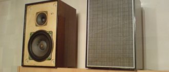
Acoustic systems "Vega 15AC-404" are designed for high-quality reproduction of sound programs in conjunction with household equipment. These speakers were used to equip such devices as the combined device “Vega-117S”, “Vega-115S”, “Vega-109S”, the electrophone “Vega-104S”, etc. Loudspeakers 25GD26 and 3GD31 (or 5GDV) are installed inside. Rated power 15 W. Operating frequency range 63…20000 Hz. AC input impedance 4 ohms. On Datagor there is an article by Sergei Vilkov Remaking the Vega 15AC-404 acoustic systems. I went a little further on this path. I bring to your attention a photo report of the conversion of old Soviet speakers “Vega 15AC-404” from the Berdsk Radio Plant.
A complete change of the exterior, a transition to modern and bright.
25AS-109, also known as 25AS-309
They were produced by the Berdsk Radio Plant.
25AS-109 since 1982. And under the name 25AC-309 since 1985. GOST has changed - the name has changed. 3-way closed-type loudspeaker - designed to work with high-end amplifying household radio equipment.
Those. characteristics:
| Frequency range, Hz: | 40-20 000 |
| Average sound pressure, Pa | 1.6 |
| Nominal electrical resistance (nominal value of electrical impedance). Ohm | 4 |
| Rated power, W | 25 |
| Nameplate power: | 35 |
| Decor | Closed box |
| Weight, kg, no more | 13 |
| Dimensions, mm | 480x285x261 |
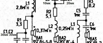
Speakers: LF: 35 GDN-1-4 (25 GD-26B) MF: 20 GDS-4-8 (15 GD-11A) HF: 5 GDV-1-8 (3 GD-31)
Description: The case is made in the form of a box with a removable back cover. Valuable wood veneer. Varnish coating in several layers. Inside the case there is a bag of cotton wool to dampen resonances. At the bottom of the speaker there is a filter board. The midrange speaker is separated from the main volume by a plastic cap, inside of which there is also cotton wool.
The tweeters and midrange speakers are mounted on the outside of the speaker, and the woofer on the inside. The front, speakers and front panel are covered by a single plastic cover, which serves as both a decorative and protective element. It is held on by screws located on the inside of the front panel. At the bottom of the speaker there is a filter board. It uses coreless coils and MBGO capacitors. Resistors C5-35.
Various options for speaker modifications by different enthusiasts:
Four screws, a couple of nails and a garnish file - that's what will help turn your old electric kettle into a wonderful haymower!
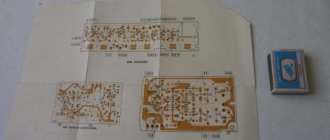
The weakest link of the AC 25AC-109 (25AC-309) is the high-frequency head ZGD-31 (new name 5GDV-1-8), which does not allow for clear sound of the entire speaker. The sound quality can be significantly improved by replacing the speaker with a more modern and powerful 6GDV-4-8 (see figure), the flanges of both heads are the same, so the replacement does not require any additional modifications to the speaker body and allows you to keep its appearance unchanged. The new head is installed on the inside of the front panel of the speaker. To improve the sound of the 25AC-109, it is necessary to make some changes to the high-pass and mid-pass filters. In the first of them, the resistance of resistor R3 should be reduced from 5.1 to 3 Ohms and the capacitances of the capacitors should be increased: C3 - from 2 to 3 μF and C4 - from 1 to 2 μF. In the second filter, it is recommended to remove the coil and reduce the resistance of resistor R2 from 5.1 to 3 Ohms, and connect the C5R4 chain in parallel with the 20GDS4-8 midrange head. In some batches of 25AS-109 there is no coil in the midrange filter. However, the modification of such speakers is carried out using the same method.
In order to equalize the frequency response of the midrange head 20GDS-4-8 and reduce nonlinear distortions, it is recommended to perform acoustic damping of this head.
To do this, the window of its diffuser holder should be sealed with synthetic felt, and the sealing box should be completely filled with sound-absorbing material. After the described alteration, the sound of the 25AC-109 becomes cleaner and is only slightly inferior to such well-known acoustic systems as the 35AC-012 (S-90). Y. DLI. Nizhny Novgorod When I decided to redo it and disassembled the speakers, I was amazed at the sloppiness of their manufacture. The speakers manufactured in 1986 had cracks, the inner surface of the plywood housing did not withstand any criticism at all, the midrange cap of one of the loudspeakers was burned through with a soldering iron, the installation of the speaker elements differed from the circuit diagram given in the operating instructions. This is how I paid for my trust in the manufacturer. The sound of the speakers before the modification was terrible. It seemed that all the heads were connected in parallel, without separating filters. The high-frequency components of the sound signal were almost not audible; the low-frequency head reproduced half of the sound range, the other, as best it could, was reproduced by the mid-range head. Although when finalizing the acoustics I was mainly guided by V. Shorov’s recommendations, I would still like to supplement his article with a few comments. In amateur radio conditions, it is difficult to adjust the gap with a magnetic gasket in the magnetic core of the L3 coil (designations according to V. Shorov’s article), so I used a coil without a magnetic core with an inductance close to the recommended one. The frame is made of wood; it is a cylinder with a diameter and height of 40 mm with square cheeks 90X90 mm made of plywood 5 mm thick. The winding contains 264 turns of PEL 1.4 wire. In loudspeakers, this coil was placed under the HF heads and secured with screws. As resistor R4, I used a piece of nichrome wire, which was wound around an MLT-2 resistor with a resistance of 100 kOhm. The resistor itself was installed on the factory board. I would not recommend increasing resistor R3 from 5.1 to 8.2 Ohms. since the equipment is equipped with loudspeakers “25AC-109”. has a slight gain at frequencies of 17...20 kHz and when using a resistor with a resistance of 5.1 Ohms (with 100% input of the HF tone control), a feeling of reproduction of a wider frequency range is created. I did not remove the midrange heads from the speaker housings, but only removed the caps. I didn’t use PAS: I took a piece of foam rubber 15 mm thick, cut a hole in it according to the size of the magnetic system of the midrange head and. putting it on the head, screwed the cap on with screws, pressing the protruding parts of the foam rubber around the perimeter. I coated all the seams of the speaker cabinets with epoxy putty, after which I covered their entire internal surface with mats made from four quilted synthetic mats 5 mm thick. After this modification, the sound quality of the speakers improved significantly. The transparency of the sound has sharply increased, the mumbling at lower sound frequencies has disappeared, and the output at higher frequencies has increased. S. Maksimov. Surgut A simple modification of the “25AS-109” acoustic system will significantly improve its sound quality. This will not require large expenses from the radio amateur and will not change the appearance of the speaker. You just need to replace the long-outdated 5GDV-1 head with a more modern 4GDV-1 and install a bass reflex. First of all, you need to remove the back wall and front panel of the speaker, remove the 5GDV-1 head from the case and cover the inner surfaces of the side, top and rear walls of the speaker with foam rubber (felt or batting). After this, the separation filter should be modified in accordance with the one shown in Fig. 1 with a schematic diagram and, without connecting the high-frequency head, put the back wall of the speaker cabinet in place. Then start making the bass reflex tunnel. Since the exact calculation of its length is very difficult, it is proposed to select it experimentally. To do this, make a test tunnel from a sheet of drawing paper without a cutout for the wires. Unlike the real one, its length should be 25 cm. The test tunnel is inserted into the hole of the high-frequency head and, by applying a signal with a frequency of 30...40 Hz to the input of the crossover filter, moving the tunnel in the hole of the head, its optimal length is set at the maximum volume level. A real bass reflex tunnel is made from ebonite or cardboard with a cutout for wires (Fig. 2) and a length corresponding to the selected length of the trial tunnel. Then the back wall is removed and the front panel is put in place. Next, take the 4GDV-1 head, remove the fastening ring from it and glue it again with “Moment” glue in its original place. After this, the head is glued to the grid of the high-frequency head strictly in the center of the corresponding hole in the front panel, where the 5GDV-1 high-frequency head previously stood. As a result, the 4GDV-1 head, the “25AS-109” mesh, or rather the front panel itself form a single whole. Since the newly installed head is much smaller than the old one, slots are formed around it, which are used in the phase inverter. Finally, 4GDV-1 is connected to the separation filter, a tunnel is installed and glued to the front panel (Fig. 3). Now all that remains is to put the back wall in place - and the speaker is ready for use. You should pay attention to observing the polarity of connecting the heads (see Fig. 1), because the sound quality of the speakers depends on this. G. Bekeris. Kaunas