A little history
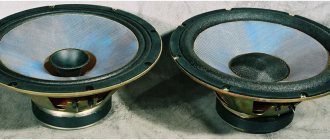
Today the legendary Radiotehnika S90 speaker system arrived in our workshop; the speakers need to be repainted! Many of us had such a speaker, many dreamed of it. They sounded in clubs and concert halls. These are the first domestic HI-FI class speakers! Teenagers from Soviet times dreamed about them; they occupied places of honor in assembly halls, technical schools, schools and universities. Their owner was certainly proud of the Radiotehnika S90 speakers; they aroused envy in the eyes of the common people and brought indescribable pleasure to their owners. These speakers are rightfully considered the best acoustic system in the USSR. The first release of the Radiotekhnika S90 speakers took place in 1977. The development was carried out by the Orbita Design Bureau, and production took place at Rizhsky. Well, let me introduce our guests Radiotekhnika S90.
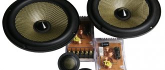
Original Radiotehnika speakers
And here radio amateurs can download the diagram of these speakers for free.
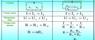
Scheme s-90
Modernization of S-90 according to Rogozhin
The article is devoted to new methods of improving the sound of the widely used S-90 speakers. A well-known sound engineer and acoustic system designer from Kyiv, specializing in studio equipment and acoustic systems, proposed a “People's Project” to convert the S-90 speakers to a labyrinthine acoustic design. Author: Alexander Rogozhin. The work was carried out according to the original article. Alexander Rogozhin came up with the know-how of how to convert the Radiotekhnika S-90 speakers, most well known to most Russian-speaking people, into labyrinthine housings. The article is devoted to the most widespread and for more than 20 years considered the standard acoustics of the Soviet period, which in its first generation was called 35 AC-1.
In the late USSR, in addition to the S-90 speakers, of course, “clones” appeared, taken from the best foreign samples, for example, Electronics 100 AS-063 or 75 AS-065. But they were very expensive and not widespread; they could not compete in popularity with the S-90 acoustics.
Design and assembly
To make the labyrinth housing of the S-90 speakers, it is best to take 16 mm thick material. There are several reasons for this: First - the new case should not be “overbearing”, Second - the design of the labyrinth, this is when there are many partitions and few extended surfaces, which means the labyrinth is initially a more rigid structure than a closed box or bass reflex, Third - chipboard, MDF and plywood 16 mm thick is the most common and affordable material. With such dimensions of the speakers, it will not be possible to make do with 16 mm thick material in a phase-inverted or closed acoustic design. So the labyrinth is a clear favorite here. Ideally, the body should be made of birch plywood, but if this is not available, laminated MDF, chipboard, or even an old cabinet will do.
Two baffles are installed on the rear wall of the midrange speaker box to give the box an optimal acoustic shape and reduce parasitic resonances. You need both of them and you can’t do without them. In general, it is advisable not to change any dimensions or install any additional parts in new S-90 speaker enclosures. Each element of the body is calculated down to the millimeter and is located exactly where it is needed.
The drawing does not indicate the diameters of the installation holes for the speakers because... the heads that were installed in the S90 speakers were produced by many enterprises of the former USSR and, like everything that was made in the USSR, they do not have unique sizes. When installing speakers in new labyrinth enclosures, measure the actual dimensions of the heads and transfer them to the front panel. There were many versions of speaker baskets 30 GD-2 and 15 GD-11.
Damping
A very important point: 100% of the internal surfaces of the labyrinth and mid-frequency box must be covered with sewing batting 4-6 mm thick. The thickness of the batting was taken into account when designing the speakers, and its absence or replacement with something thicker will worsen their objective performance. The batting should be glued to rubber glue or double-sided tape (in sheets), it normalizes the quality factor of the labyrinth and removes unnecessary sounds. A labyrinth without batting on the walls is the same as a car without shock absorbers. A labyrinth without batting will play the same way as a car will drive without shock absorbers (resonance of the labyrinth - spring, pasting of the labyrinth - shock absorber).
All walls on the inside of the mid-frequency box should also be covered with batting; its internal volume should not be filled with anything.
There is no need to “improve” the acoustics of the labyrinth by stuffing synthetic padding polyester, felt, cotton wool or the original absorber left over from old buildings into it. We fill the sound absorber only for the tweeter chamber and the blind “triangles” that form the channels of the labyrinth. If this is not done, after assembly the triangles will turn into resonators and each at its own frequency will begin to “howl” through the walls of the speakers.
Sound
To date, one pair of labyrinth housings has been manufactured. The speakers were assembled and tested in comparison with the standard stock Radiotekhnika S-90 speakers. I guarantee that many of the music lovers who decide on such a conversion from a phase-inverted design to a labyrinth one, in addition to the 100% BEST labyrinth bass, will probably discover the concept of a “real sound stage”.
The positive changes in sound you will experience are through the roof. And most importantly, it’s practically free, especially if you compare the cost of these cases with the price tag of similarly performing branded speakers.
Based on materials from: aovox.com
S90 replacement of speakers with imported ones
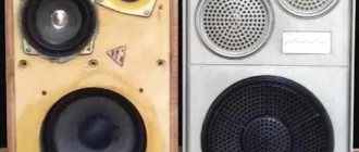
Acoustic systems AS-35 (S-90) are known as one of the best acoustic systems of pre-perestroika times. They were produced by different factories and in slightly different configurations, without changing in essence. For the modification, systems 35AS-012 GOST 23262-88 of the Bryansk Electromechanical Plant, produced in January 1990, were used. They contain speakers 75GDN-3-4, 20GDS-3-4, 10GDV-2-16 and are designed for a frequency range of 40-25000 Hz (resistance 4 Ohms).
The modification made it possible to reduce the unevenness of the frequency response at medium frequencies and get rid of the characteristic “clunking” and harshness at high frequencies by replacing the high-frequency head and damping the mid-frequency one. For the conversion, HF speakers from Peerless 100 DT 26 72 SF FF WA 8 (catalog number 811827) were used. Quite a good option, especially if you don’t mind the prospect of spending about $53 on them, which is comparable to the cost of the S-90 itself.
So, during the work process the following changes were made:
- Replacing the HF head with an imported one.
- Installation of an insulating box for the RF head.
- Midrange head damping.
- Changing the crossover frequency.
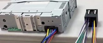
- Replacing terminal blocks with screw connectors with bi-wiring capabilities.
- Replacing the internal wiring of the speaker system, sealing the housing, installing spacers.
- Installing the speaker system on spikes
As a result of these changes, the sound of the speaker system has changed for the better. The “clinking”, whistling and lisping sounds at high frequencies have disappeared. The sound stage has expanded, acquiring greater depth and transparency. Low frequencies sounded more elastic and clear. The sound of the speakers has become more natural and natural.
A Peerless 811827 head with magnetic fluid in the gap was chosen for replacement. Maximum power 130 W, impedance 8 Ohm, resonant frequency 1130 Hz and sensitivity 92 dB. The external dimensions of this head are slightly smaller than the standard one, and the impedance is two times lower. This necessitated the need to manufacture an insulated box for it and change the values of the elements in the crossover circuit.
The box was made of two squares (11x11cm) of 10mm plywood. A hole with a diameter of 90 mm was cut in one of the squares, and a small sample was made at the end for signal wiring. In the second square, 4 holes are made for the head mounting screws or attachment points for screws are marked. The squares, after laying the wire, are fastened with 4 small screws with plasticine coated on the joint surface for sealing, and with plasticine coated they are installed coaxially with the hole for the HF speaker head from the inside.
The RF head is installed in the resulting box with a diameter of 90 mm and a depth of 30 mm. The head is installed through a thin rubber gasket with 4 screws or screws (at least 50mm long). These screws finally tighten and secure the entire “package”. A protective mesh and its fastening are installed on top through a standard rubber gasket.
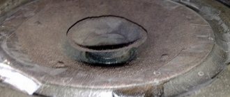
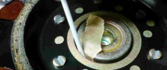
Damping the midrange head consisted of sealing the windows in its basket with a strip of thin white calico. A strip of calico 15cm wide is glued into a tube and glued to the base and edges of the basket with instant glue. The second hole of the pipe is collected and tied like a pouch.
The crossover consists of three stripes. Remaking the low-frequency part consists only of separating it from the other two filters and connecting it to separate terminals of the new block. The standard hole in the rear wall is enlarged to the size required to install a new terminal panel.
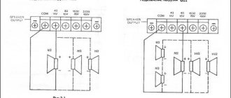
We reduce the frequency of the MF-HF section by 2 times. This means a 2-fold increase in the corresponding inductances and capacitances. In the midrange filter these are L3 and C5. I had parts from similar crossovers, so I did not change the inductance L3 to twice as large, but simply connected another one, the same (Ls), in series. The capacitance of capacitor C5 was 4 μF; to increase it, capacitance Cs was connected in parallel, consisting of two MBGO-2 2 μFx160V capacitors.
In a high-pass filter, simply increasing the values twice is not enough. Considering that the impedance of the RF head has been halved, the capacitance needs to be doubled and the inductance needs to be halved. In total, the inductance remains unchanged, and the capacitance increases 4 times. In the original version, they were 2 μF (C1) and 1 μF (C2). Calculated 2.25 µF and 0.75 µF, new values selected 10 µF and 3 µF. Instead of C1, a capacitor MBGO-2 10 μFx160V (Cn) is installed, and C1 is connected in parallel with C2, forming a total capacitance of 3 μF.
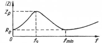
The crossover frequency has decreased by 2 times to 2500Hz, which is more than 2 times higher than the resonant frequency of the HF head, and taking into account the third-order filter in the crossover, this makes it unnecessary to install a notch filter at the resonant frequency.