You have probably noticed more than once that on the wires from a laptop, monitor and other electronic equipment there are strange bulges in the form of a cylinder. This is done for a reason or for beauty. The fact is that the plastic cylinder is a special ferrite filter. People often call it a filter for suppressing high-frequency interference, or more simply, a “noise” filter. Why and what is it needed for?
The fact is that any device connected to the electrical network is a source of electromagnetic waves, which, in turn, are high-frequency interference that affects the operation of other devices located nearby. Long external power and interface cables act as a kind of antennas, which quite strongly emit interference into the external environment that is created by the equipment during operation. This can greatly affect the operation of WiFi wireless networks, radio equipment and precision instruments. To prevent this from happening, the cable must be shielded. But then its price will rise significantly! A ferrite ring and filters made of this material came to the rescue.
Why are ferrite rings needed on cables?
Why are ferrite rings needed on computer cables and what is their effect?
Internal and external computer cables can act as miniature antennas as they convert voltage and current noise into electromagnetic radiation.
Ferrite rings for flat and round cables provide effective suppression of noise currents before they are emitted as electromagnetic interference.
Unshielded cables emit noise due to common-mode noise flowing through their copper conductors, that is, high-frequency current flowing in the same direction throughout all cable conductors. These currents create a magnetic field of a certain magnitude and direction.
Cable ferrites attenuate noise currents by “capturing” the magnetic field and dissipating some of its energy in the form of heat, i.e., a ferrite element placed on the cable conductors creates a high active impedance for common-mode currents. Ferrites can be used on internal AC or DC power cables and on conductors carrying analog and digital signals.
Manufacturers of electronic equipment use ferrites to suppress electromagnetic radiation from external power and signal cables of computer system units, monitors, keyboards, printers and other peripheral devices.
Long external power and signal cables act as antennas, effectively radiating interference generated inside the device to the outside environment. The use of ferrite products reduces the shielding requirements for external cables and, in many cases, makes it possible to reduce their cost.
Cable ferrites for EMI suppression should be selected based on the specific application; the cable ferrite should produce the maximum series impedance for the noise signal frequencies.
Once the core material and approximate dimensions have been selected, the series impedance it produces and the noise reduction performance can be optimized by:
1. Increasing the length of the part of the conductor covered by ferrite; 2. Increasing the cross-section of the ferrite core (especially for power circuits); 3. Selecting a core with an internal diameter closest to the external diameter of the conductor or cable;
In general, the best ferrite core is the longest and thickest that can be placed on the cable, with an internal diameter that matches the external diameter of the cable. When installed on flexible cables, solid ferrite cores must be encased in heat shrink tubing or otherwise protected and secured in place.
The series impedance introduced by the high-frequency ferrite core can be increased by making several turns of conductor on it. According to the theory, impedance increases in proportion to the square of the number of turns. However, due to the nonlinearity of ferrites and losses in them, two turns on the core will increase the impedance not by four times, but somewhat less.
In most cases, the ferrite should be located as close as possible to the source of interference, which will prevent the transmission of interference through other elements of the device design, where it is much more difficult to filter out.
But for data cables where conductors enter or exit a shielded housing, the ferrite cores should be placed as close as possible to where they pass through the shield. This will prevent the conductors inside the housing after the filter from emitting noise.
Source: https://faqhard.ru/base/12/01.php
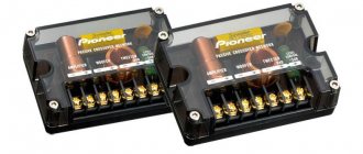
Selection and application of Chilisin chip filters
To select the optimal type of ferrite chip filter, the spectrum of interference, the required level of suppression and the range of operating currents are first determined. Based on the application conditions, the impedance and permissible DC resistance of the chip filter are selected. Based on the obtained parameters, a series and type of chip filter with the required effective noise suppression band is selected. The current value and resistance are especially important when installing chip filters in power circuits. First of all, you need to choose types that ensure the filter operates without saturation. The DC resistance value will ensure the minimum voltage drop.
Table 3. Characteristic impedance values for various circuits
Typical applications for ferrite chip filters are:
- filtering “ringing” in data lines;
- supply voltage decoupling;
- land decoupling.
The filtering effect increases with:
- using shunt capacitors connected to ground. The choice of capacitor value depends on the interference spectrum and attenuation frequency;
- low output impedance of the source.
Chip filters are usually installed as close as possible to the interference source device in order to reduce the effective length of the antenna wire with high-frequency noise.
Why do you need a ferrite filter or ring on the cable?
You have probably noticed more than once that on the wires from a laptop, monitor and other electronic equipment there are strange bulges in the form of a cylinder. This is done for a reason or for beauty. The fact is that the plastic cylinder is a special ferrite filter. People often call it a filter for suppressing high-frequency interference, or more simply, a “noise” filter. Why and what is it needed for?
The fact is that any device connected to the electrical network is a source of electromagnetic waves, which, in turn, are high-frequency interference that affects the operation of other devices located nearby. Long external power and interface cables act as a kind of antennas, which quite strongly emit interference into the external environment that is created by the equipment during operation. This can greatly affect the operation of WiFi wireless networks, radio equipment and precision instruments. To prevent this from happening, the cable must be shielded. But then its price will rise significantly! A ferrite ring and filters made of this material came to the rescue.
Glory to ferrite: how to deal with interference from gadgets on the radio in the car
If suddenly the radio reception in the car becomes poor, do not rush to blame the radio! It is quite possible that you just recently bought and installed some new car gadget, and it is causing interference to the FM broadcast. To combat such a problem, there is a true old-fashioned method!
Radio interference from gadgets
Actually, we will not argue that the described problem in the auto world is downright widespread, but, nevertheless, it occurs from time to time. You turn on a new gadget in the car - and it interferes with the radio receiver of the audio system or, say, with a CB radio station or Bluetooth handsfree...
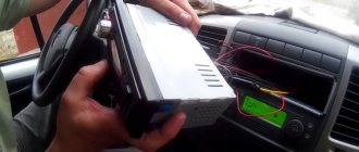
At one time, my car navigator gave such interference, a couple of friends had tablet chargers and a radar detector. In all cases, it was possible to overcome the problem by installing a ferrite choke filter on the device’s power cable - in fact, responsible manufacturers initially install such filters on power and data cables. But since there is most often no need for them, rather than vice versa, they try to save on “useless” parts...
The filter in a power cord or data cable is a simple inductor with a core.
“Correct” wire with factory-installed ferrite filter
The wire through this coil makes, in fact, only half a turn, passing through the ferrite cylinder once, but this, as a rule, is enough to suppress high-frequency interference sometimes generated by gadget chargers and the gadgets themselves.
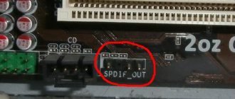
Inside the filter, under a layer of plastic, there is such a ferrite ring-shaped “barrel”
Ferrite "latches"
Actually, making a ferrite choke on a cable is very easy. The simplest thing is to use the so-called “latch”. This is a special element for suppressing interference in the wires of existing equipment - it is placed on the cable without requiring it to be disconnected, cut or unsoldered. Inside the “latch” there is a ferrite “barrel” sawn lengthwise - when installed, the “latch” opens, a wire is passed between its halves, and the body closes. The device will work even more efficiently if you don’t just pass a wire through it, but make a couple of turns. Such a filter can be bought in radio component stores or ordered from Chinese online stores.
The “latch” is mounted like this:
Source
How does a ferrite filter work?
Ferrite is a special material consisting of a compound of iron oxide and a number of other metals that does not conduct current and effectively absorbs electromagnetic waves. The ferrite ring is an excellent magnetic insulator and thus filters out high-frequency interference and electromagnetic noise. It absorbs the electromagnetic waves coming out of electronic equipment before they are amplified in the cable, as in an antenna.
A ferrite filter is a cylinder-shaped core made of this material, which is put on the cable either immediately in production or later. When installing it yourself, it must be located as close as possible to the source of interference. Only this will prevent the transmission of interference through other elements of the device’s design, where it is much more difficult to filter it out.
Interesting on the topic:
Share useful information with friends:
One review
I had previously guessed that the barrels at the end of the power cables are noise filters. But the device represented them as inductors, possibly supplemented with some kind of microcircuits. I was even more convinced of this when the charging unit for the computer suddenly stopped charging, although there was voltage at its output. There was no time to understand the reasons, so I bought a new block (with a new barrel). Being burdened with an engineering education, I finally decided to understand the causes of the malfunction. Voltage measurements after the keg showed a reduced value (around 17 volts), while at the output of the old charging circuit (i.e. at the input of the keg) 19.2 V was clearly recorded. In addition, the voltage after the keg (even without load) “walked” before our eyes, showing sometimes more than 17, sometimes less. “So, the charger is working properly, but in this barrel there is a non-linear faulty element hidden, which reduces the charging voltage more than permissible,” I thought. Guided by this thought, I cut off the barrel along with the plug from the old charger and instead replaced the old cord with a new cord with a new barrel and plug. This is how my computer works now (and the new charger with the cut cable is gathering dust on the shelf). Imagine my surprise when I gutted the old (faulty?) barrel with a plug and found nothing there except a ferrite bushing! Moreover, I discovered that the positive conductor in the old charger was completely inside the negative conductor enveloping it, i.e. was completely shielded, and interaction with the ferrite filter was thus reduced to zero. In other words, interference due to the antenna effect did not penetrate into the computer due to shielding, but nothing prevented the interference produced by the charger from penetrating into the computer through the active conductor. So what caused the voltage at the charger plug to drop and jump? Who will undertake to explain?
So that's why there's this thickening on the wire!
Have you ever noticed a small cylinder on your laptop's power cable? If not, take a closer look at charging any laptop computer. There is a small plastic barrel on the cord near the connector that is inserted into the laptop.
No, of course I knew that there was not some kind of complex device there and not just a piece of plastic, but I still couldn’t get around to finding out everything exactly and in more detail.
It turns out that this inconspicuous cylinder performs a very important function! It plays the role of a high-frequency filter and neutralizes interference that may come from the power cable. This device is called a ferrite ring, or ferrite filter.
Surprisingly, there are no microchips or other electronic devices inside this barrel. If you open it up and look at the insides, you won’t see anything interesting there. The cord simply passes through a small hollow cylinder of hard material. In some cases, the cord loops around it.
This cylinder is made of ferrite - a chemical compound of iron oxide with oxides of other metals, which is essentially a magnetic insulator. Eddy currents do not arise in this substance, so the ferrites very quickly remagnetize in time with the frequency of the electromagnetic field.
It's no secret that any unshielded power cable is a source of electromagnetic interference, which can distort information signals inside the computer. And the ferrite ring plays the role of a filter and prevents the spread of this interference.
Previously, shielding of the entire cable with copper braiding was used for this purpose, but ferrite rings are much cheaper, which is why they are widely used in modern electrical engineering.
By the way, ferrite rings not only prevent the formation of unwanted electromagnetic fields, but also protect the signal inside the cable from external interference. Therefore, such cylinders, in addition to power cables, can also be found on connection cords for monitors, cameras or cameras.
Ferrite filter - what is it for?
In our everyday life, a huge variety of computer technology has appeared that operates on high-frequency currents. After all, the higher the frequency, the higher the speed of information processing.
However, high-frequency currents impose a number of technical limitations on connecting cables for transmitting such signals. This is primarily due to side electromagnetic radiation and interference (PEMIN).
Interference on long wires has a particularly noticeable effect - after all, the signal tends to attenuate, and the cable itself acts as an antenna and therefore stray currents can arise inside it. And this has a detrimental effect on the quality of signals passing through the cable.
The simplest way to combat PEMIN is to increase the inductance.
Inductance is an indicator of the relationship between the amount of current passing through a circuit and the magnetic flux it creates. If we are talking about straight wires, then by inductance we mean a quantity that characterizes the energy of the magnetic field (here the current is considered a constant value).
The inductance can be increased by using a special ferrite ring. You can see what ferrite filters look like on cables in the photo below.
Ferrite beads are electrical circuit components that are used as passive elements to filter high-frequency interference by increasing the inductance of the conductor and absorbing interference above a specified threshold.
Such properties of a ferrite filter are given by the material from which it is made – ferrite.
Ferrite is the general name for compounds based on iron oxide and oxides of other metals. Ferrites combine the properties of ferromagnets and semiconductors (sometimes dielectrics) and therefore are used as coil cores, permanent magnets, act as absorbers of high-frequency electromagnetic waves, etc.
Multilayer Ferrite Chip Filters
For surface mounting, the design of ferrite filters is realized through the use of multilayer film structure technology. To increase the efficiency of filters in small volumes, high density inductance is required. For this purpose, an integral winding made on a multilayer film structure is used.
On each layer of a thin substrate, a film structure of a half-turn winding is formed. One turn of the winding is performed on two layers. By sintering tens or hundreds of layers, sections of conductors are connected, resulting in the formation of a three-dimensional coil with a ferrite rod inside. The layers can be located both in the horizontal plane (standard design) and in the vertical plane (filters for the microwave range above 1 GHz). Figure 1 shows the layer topologies in the ferrite chip filter structure.
The structure uses manganese-zinc and nickel-zinc ferrite films. The use of different ferrite materials, sizes, and layer topologies provides chip filters with different parameters.
Figure 2 shows the structure of a chip filter with a horizontal topology of integral winding layers.
Using an additional coil structure instead of a conventional monolithic ferrite rod allows for higher impedance in a smaller package. In fact, a certain part of ferrite chip filters are designed exactly like a ferrite rod with two electrodes.
Ferrite chip filters for filtering electromagnetic interference are manufactured using multilayer technology using nickel-zinc ferromagnetic materials. Figure 3 shows the structure and formation process of multilayer ferrite chip filters. The coil structure is formed in several layers of ferrite material.
The technology for producing multilayer ferrite EMI filters is exactly the same as for the production of multilayer chip inductors. Only in them different types of materials are used to form ferrite layers. For ferrite chip filters, a material with high absorption is used, and for chip inductors, on the contrary, with less absorption at high frequencies.
Ferrite chip filters are very similar in appearance to ceramic capacitors. Figure 4 shows the appearance of the Chilisin ferrite chip filter.
Snap-on ferrite cable filters - operating principle
The performance of a ferrite filter directly depends on the characteristics of the material from which it is made. Due to special additions of oxides of various metals, the properties of ferrite change.
There are fundamentally several ways to use ferrite rings:
- On single-core (single-phase) wires, it can, on the contrary, absorb radiation in a certain range, converting interference into thermal energy. In this way, negative frequencies can be absorbed (cut off) by the ferrite ring.
- On single-core wires, where it works as a kind of amplifier, as it returns part of the high-frequency magnetic field back into the cable, which leads to amplification of the signal in a given range.
- On stranded wires, the ferrite acts as an in-phase transformer that passes unbalanced signals in the cable (current pulses, for example, in data cables or DC power circuits) and suppresses symmetrical signals (which can potentially be caused in such cables only by electromagnetic interference).
Where to use and how to choose a ferrite filter
If we talk about the practice of application, then on power cables, ferrite rings are used to reduce interference that the cables themselves can create, and on signal (transmitting data) ferrites dampen possible external interference and interference.
Ferrite cable filters can be built-in (the cable is sold already with a ferrite ring) or separate (most often these are models that snap around the wire), which do not require any modifications to the cable itself.
The wire can be inserted into the center of the ferrite filter (a single-turn coil is obtained), or it can form several turns around the ring (toroidal winding). The latter method significantly increases the efficiency of the filter.
To select a ferrite ring to meet the specified requirements, you need to know the characteristics of the material from which it is made and the dimensions of the product.
As an example, the table below shows the main characteristics of ferrite filters offered on the market.
Source: https://filteru.ru/ferritovyi-filtr/
Impedance Frequency Characteristics of Ferrite Chip Filters
The equivalent circuit of a ferrite chip filter is an inductance and resistance connected in series.
The amount of resistance strongly depends on the frequency of the passing signal. Ferrite EMI filters are inductors with high magnetization reversal losses. This feature is the main difference between chip filters and chip inductors.
Chip filters are made from special ferrites with high magnetization reversal losses. This energy is released in the form of heat. Heat is generated through active resistance, not through inductance! The impedance of a chip filter is determined by two components: active and reactive. Formula for determining impedance:
where R is the active component and X is the reactive component. Both components are frequency dependent. The documentation for the chip inductance for each series provides the frequency characteristics of the impedance and its components. Figure 5 shows a typical impedance frequency response of a ferrite chip filter. X is the reactive part of the impedance, R is the active part, Z is the total impedance.
As can be seen from the figure, after 30 MHz the active resistance prevails over the reactive one. Below the resonant frequency, the component's impedance is essentially determined by the inductive component. In the range of 50...100 MHz the situation changes. The active component of losses dominates with increasing frequency, and the inductive component tends to zero. The impedance of chip filters increases with frequency, which is also typical for chip inductors. The main characteristic of inductive impedance (Z) is reactance (X). On the other hand, since the filter is based on ferrite material, which has high losses at high frequencies, the main characteristic in the high frequency range is the resistive component (R). Compared with conventional inductance, ferrite chip filter has better EMI energy absorption ability, providing high-frequency noise suppression effect.
Ferrite filter - what is it for?
In our everyday life, a huge variety of computer technology has appeared that operates on high-frequency currents. After all, the higher the frequency, the higher the speed of information processing.
However, high-frequency currents impose a number of technical limitations on connecting cables for transmitting such signals. This is primarily due to side electromagnetic radiation and interference (PEMIN).
Interference on long wires has a particularly noticeable effect - after all, the signal tends to attenuate, and the cable itself acts as an antenna and therefore stray currents can arise inside it. And this has a detrimental effect on the quality of signals passing through the cable.
The simplest way to combat PEMIN is to increase the inductance.
Inductance is an indicator of the relationship between the amount of current passing through a circuit and the magnetic flux it creates. If we are talking about straight wires, then by inductance we mean a quantity that characterizes the energy of the magnetic field (here the current is considered a constant value).
The inductance can be increased by using a special ferrite ring. You can see what ferrite filters look like on cables in the photo below.
Ferrite beads are electrical circuit components that are used as passive elements to filter high-frequency interference by increasing the inductance of the conductor and absorbing interference above a specified threshold.
Such properties of a ferrite filter are given by the material from which it is made – ferrite.
Ferrite is the general name for compounds based on iron oxide and oxides of other metals. Ferrites combine the properties of ferromagnets and semiconductors (sometimes dielectrics) and therefore are used as coil cores, permanent magnets, act as absorbers of high-frequency electromagnetic waves, etc.
Installation of chip filters at the LVDS cable connection points
Cable connection between the laptop motherboard and the LCD display increases the level of noise emitted by the computer due to harmonics of LVDS signals and interference from integrated circuits located along the signal transmission line. Since the frequency of transmitted LVDS signals reaches hundreds of megahertz, it is recommended to use NB series chip filters to prevent signal waveform distortion and suppress common-mode interference. When transmitting differential LVDS signals, the magnetic fluxes created by the flowing current cancel out, resulting in reduced interference. However, the presence of reflected signals can lead to unequal currents flowing through pairs of conductors. In this case, common mode chokes act as transformers to balance currents, which ultimately reduces the level of electromagnetic interference.
Snap-on ferrite cable filters - operating principle
The performance of a ferrite filter directly depends on the characteristics of the material from which it is made. Due to special additions of oxides of various metals, the properties of ferrite change.
There are fundamentally several ways to use ferrite rings:
- On single-core (single-phase) wires, it can, on the contrary, absorb radiation in a certain range, converting interference into thermal energy. In this way, negative frequencies can be absorbed (cut off) by the ferrite ring.
- On single-core wires, where it works as a kind of amplifier, as it returns part of the high-frequency magnetic field back into the cable, which leads to amplification of the signal in a given range.
- On stranded wires, the ferrite acts as an in-phase transformer that passes unbalanced signals in the cable (current pulses, for example, in data cables or DC power circuits) and suppresses symmetrical signals (which can potentially be caused in such cables only by electromagnetic interference).
Where to use and how to choose a ferrite filter
If we talk about the practice of application, then on power cables, ferrite rings are used to reduce interference that the cables themselves can create, and on signal (transmitting data) ferrites dampen possible external interference and interference.
Ferrite cable filters can be built-in (the cable is sold already with a ferrite ring) or separate (most often these are models that snap around the wire), which do not require any modifications to the cable itself.
The wire can be inserted into the center of the ferrite filter (a single-turn coil is obtained), or it can form several turns around the ring (toroidal winding). The latter method significantly increases the efficiency of the filter.
To select a ferrite ring to meet the specified requirements, you need to know the characteristics of the material from which it is made and the dimensions of the product.
As an example, the table below shows the main characteristics of ferrite filters offered on the market.
Source: https://filteru.ru/ferritovyi-filtr/
Main parameters of Chilisin ferrite chip filters
The main parameters by which chip filters are selected are: operating frequency range, impedance at a test frequency of 100 MHz (in Ohms), DC resistance (in Ohms), maximum permissible current, permissible impedance deviation from the nominal, form factor ( housing dimensions), as well as operating temperature range.
The nominal impedance is usually given at a frequency of 100 MHz. For the microwave range, typical impedance values are given at a frequency of 1000 MHz.
The permissible deviation from the nominal value is given in relative units. Dimensions, impedance rating, and impedance spread are included in the component name. To select the required filter, it is important to know other parameters that are not given in the name. They are given in the technical documentation for the component. This:
- DC inductance resistance (in Ohms);
- maximum operating current at which the ferrite inductor material does not saturate (in mA);
- type of impedance frequency response.
Table 1 shows possible sizes for Chilisin ferrite chip filters.
Table 1. Standard sizes of Chilisin ferrite chip filters
| Code | Size (LxWxH), mm | EIA Code |
| 060303 | 0.6×0.3×0.3 | 0201 |
| 100505 | 1.0×0.5×0.5 | 0402 |
| 160808 | 1.6×0.8×0.8 | 0603 |
| 201209 | 2.0×1.2×0.9 | 0805 |
| 201212 | 2.0×1.2×1.25 | 0805 |
| 321611 | 3.2×1.6×1.1 | 1206 |
| 321616 | 3.2×1.6×1.6 | 1206 |
| 322513 | 3.2×2.5×1.3 | 1210 |
| 451616 | 4.5×1.6×1.6 | 1806 |
| 453215 | 4.5×3.2×1.5 | 1812 |
Ferrite ring - what is it? How to make a ferrite ring with your own hands?
Each of us has seen small cylinders on power cords or coordination cables for electronic devices. They can be found on the most common computer systems, both in the office and at home, at the ends of the wires that connect the system unit with the keyboard, mouse, monitor, printer, scanner, etc. This element is called a “ferrite ring” (or ferrite filter). In this article we will look at the purpose for which manufacturers of computer and high-frequency equipment equip their cable products with the mentioned elements.
Advantages and disadvantages
Ferrite consists of a compound of metal oxides. The compounds include iron, nickel, zinc and other metal oxides that have low electrical conductivity as well as magnetic properties. Ferrites have no competitors among materials with magnetic properties that absorb high-frequency interference.
Ferrite device on a single-phase cord:
During the filtering process, an antiphase pulse (useful information pulse) passes through a multi-core cable and interference is reflected. Install devices on power, video, audio, USB cables.
To avoid incorrect data transmission, you need to use high-frequency ferromaterials and do not install a wave-absorbing type of device.
Main purpose
The ferrite ring can reduce the effect of radio frequency and electromagnetic interference on the signal that is transmitted through the wire. Long signal and power cables of both computer and other power equipment have parasitic properties, that is, they act like antennas. They very effectively radiate into the external environment various noises that are created inside the device, thereby creating interference with radio stations when receiving radio signals and other electronic equipment. Conversely, receiving interference from radio transmitting devices, a computer or other electronic device may malfunction. To eliminate this phenomenon, they use a ferrite ring placed on the supply or matching cable.
Filter design
Most often, electronics engineers and radio amateurs use filters in the shape of cylinders or rectangles. They are available with latches that allow you to remove them from the cable, or solid cast. They are used to increase the filtering of high-frequency interference on connecting cords. At the point where the cylinder is installed in the cord, the inductance increases hundreds of times.
Cylindrical
A cylinder is an elongated ferrite device, which during manufacturing is installed by the manufacturer on power and connecting cables. They reduce interference from cord radiation on noisy appliances. The cable acts as an antenna and creates radiation of hundreds of MHz around itself. The cylinders are installed on one side of the wire from the radiation source or on both sides. Installing cylinders on wires is not a panacea for high-frequency interference. The ideal solution is built-in filters in an electronic device.
If, however, you have a wire without the necessary suppression of high-frequency magnetic radiation, then a removable cylinder with a nickel-zinc type of ferrite is necessary.
Ring shaped
The coil impedance, which is formed by turns of cable passed through a ferrite ring, is small for signals on low-frequency lines and high for high-frequency pulses. The frequency range depends on the number of turns, size and material from which the ring is made. The interference that travels along the wire through the ring is attenuated. The attenuation rate is 10–15 dB. For ease of installation, the devices are made of 2 half-rings in a plastic case with a built-in latch. This design allows you to install the ring on the wire in a couple of minutes.
In electronics, rings can be used:
To increase the impedance, you need to make several turns of wire around the device.
The impedance increases by the square - 2 turns - 4 times, 3 turns - 9 times, and 4 turns - 16 times.
It is necessary to wind the cable so that the ring snaps normally and does not push through its walls. It is necessary to calculate the turns in advance and purchase a device with the required internal diameter size.
Physical properties
Ferrite is a ferrimagnetic material that does not conduct electric current, that is, it is essentially a magnetic insulator. Eddy currents are not created in this material, and therefore it remagnetizes very quickly - in time with the frequency of external electromagnetic fields. This material property is the basis for effective protection of electronic devices. A ferrite ring placed on a cable can create a high active impedance for common-mode currents.
This material is formed from a chemical combination of iron oxides with oxides of other metals. It has unique magnetic characteristics and low electrical conductivity. Thanks to this, ferrites have practically no competitors among other magnetic materials in high-frequency technology. 2000nm ferrite rings significantly increase the cable inductance (several hundred or thousand times), which ensures suppression of high-frequency interference. This element is installed on the cord during its production or, cut into two semicircles, is put on the wire immediately after its manufacture. The ferrite filter is packaged in a plastic case. If you cut it open, you can see a piece of metal inside.
Noise Suppression in LCD Interface
The graphics controller is connected to the LCD drivers by multiple signal lines that switch simultaneously. These switchings cause a large pulse current to flow through the power and ground circuits. Therefore, the current in the signal lines must be limited. Ferrite chip filters of the NB series are well suited for these purposes. On clock signal lines, especially those operating at high speeds and at high levels of interference, filters of the HF or HP series are used, which have a high attenuation coefficient and steepness of frequency response slopes. Interference caused by transient currents also occurs in power circuits. Therefore, to suppress interference in power circuits, ferrite chip filters, as well as shunt capacitors, are installed. Table 4 shows examples of typical applications of ferrite chip filters in electronic equipment.
Table 4. Typical applications of Chilisin ferrite chip filters of various series
| Name | Application category | Typical Applications | Basic parameters | |
| Current, mA | Impedance, kOhm | |||
| Filtering interference in signal circuits with a bandwidth up to 1 GHz | ||||
| S.B. | General Application | Smartphones, consumer electronics, digital cameras | 50…500 | 0.005…2.7 |
| G.B. | General Application | Smartphones, mobile equipment | 100…500 | 0.007…2 |
| Filtering interference in signal circuits with a bandwidth of about 1 GHz | ||||
| N.B. | Digital RF signals | Video decoders, DSP circuits, Bluetouth, smartphones, digital cameras, satellite receivers, tuners | 50…500 | 0.005…2.7 |
| Filtering interference in signal circuits with a bandwidth greater than 1 GHz | ||||
| HF; HP | Microwave signals above 1 GHz | Microwave receivers and transceivers | 50…2000 | 0.12…1.8 |
| Filtering noise in power circuits with currents up to 6 A | ||||
| P.B. | General Purpose Power Circuits | DC/DC converters, video decoders, USB/IEEE1394 circuits, LAN interfaces, video cards, digital cameras | 800…6000 | 0.005…1.5 |
| UPB | High current circuits | DC/DC converters | 4000…6000 | 0.005…0.33 |
Do you need a ferrite filter? Or is this another deception?
Computers are very “noisy” (in electromagnetic terms) devices. Thus, the motherboard inside the system unit is capable of oscillating at a frequency of one kilohertz. The keyboard has a microchip that also operates at high frequencies. All this leads to the so-called generation of radio noise near the system. In most cases, they are eliminated by shielding the board from electromagnetic fields with a metal case. However, another source of noise is the copper wires that connect various devices. In essence, they act as long antennas that pick up signals from the cables of other radio and television equipment, and affect the operation of “their” device. The ferrite filter eliminates electromagnetic noise and broadcast signals. These elements convert electromagnetic high-frequency vibrations into thermal energy. That's why they are installed at the ends of most cables.
How to choose the right ferrite filter
To install a ferrite ring on a cable with your own hands, you need to understand the types of these products. After all, it depends on the type of wire and its thickness which filter (from what material) will need to be used. For example, a ring installed on a multi-core cable (power cord, data cable, video or USB interface) creates a so-called common-mode transformer in this section, transmitting anti-phase signals carrying useful information, and also reflects common-mode interference. In this case, one should not use absorbing ferrite to avoid disruption of information transmission, but a higher-frequency ferromaterial. But it is preferable to choose ferrite rings for the antenna cable from a material that will dissipate high-frequency interference rather than reflecting it back into the wire. As you can see, an incorrectly selected product can worsen the performance of your device.
Description [edit | edit code ]
A ferrite filter is one of the simplest and cheapest types of interference filters to install on existing wires. For a conventional ferrite ring, the wire is either threaded through the ring (forming a single-turn inductor) or forms a multi-turn toroidal winding, which increases the inductance and, accordingly, the efficiency of noise suppression. Also used are collapsible filters with snaps that can simply be put on the cable.
Such filters are used in two different ways, although outwardly they look the same, and you can often see the same grades of ferrites used:
- A filter installed on a single (single-core, single-phase) wire. In this case, depending on the grade of ferrite and the frequency range of the barrier of interest, it works as:
- Inductance. Some of the RF wave power is reflected back into the cable.
- Absorber. Part of the RF wave power is dissipated in the ferrite, which is more preferable.
- Mixed mode.
- A filter installed on a multi-core cable, such as a data cable, power cord, or interface: USB, video, etc. In this case, the ferrite creates an in-phase transformer on this section of the cable, which, passing antiphase signals (carrying useful information), reflects (does not pass) common mode interference. In this case, absorbing ferrite should not be used to avoid disruption of data transmission, and the use of higher frequency ferromaterials is desirable.
Ferrite cylinders
Thick ferrite cylinders cope most effectively with interference. However, it should be borne in mind that too bulky filters are very inconvenient to use, and the results of their work are unlikely to differ much in practice from slightly smaller ones. You should always use filters of optimal dimensions: the internal diameter should ideally match the wire, and its width should correspond to the width of the cable connector.
Don’t forget that it’s not only ferrite filters that help combat noise. For example, for better conductivity it is recommended to use cables with a larger cross-section. When choosing the length of the cord, you should not leave a large margin of length between the connected devices. In addition, poor quality of the connection between the wire and the connector can also be a source of interference.
Step by step application
The removable cylinder must be opened and a cord installed in it, which must be protected from electromagnetic interference. The ferrite device is installed 3 cm above the wire tip.
Close the device and the plastic locks on the case will snap into place. For greater reliability, you can install a second filter at the other end of the connecting cord.
If the cord is inserted into the center of the ring, it is a single-turn coil, and if there are several turns around the ring, it is a toroidal winding. This technique is more effective than a single-turn coil.
To select a ferrite device, you need to know the composition of the ferromaterial and its characteristics, the dimensions of this device and the parameters of the high-frequency radiation of the device.
Source
Ferrite ring markings
The most widespread type of record for marking ferrite rings is as follows: K D×d×N, where:
— K is an abbreviation for the word “ring”;
— D – outer diameter of the product;
— d – internal diameter of the ferrite ring;
— H – filter height.
In addition to the overall dimensions of the product, the type of ferromagnetic material is encrypted in the marking. An example entry may look like this: M20VN-1 K 4x2.5x1.6. The second half corresponds to the overall dimensions of the ring, and the first half encodes the initial magnetic permeability (20 μi). In addition to the specified parameters, in the reference description, each manufacturer indicates the critical frequency, parameters of the hysteresis loop, resistivity and Curie temperature for a specific product.
Designation system for Chilisin multilayer ferrite chip filters
Figure 6 shows the designation system for Chilisin ferrite chip filters. This designation system is applicable for the following series of Chilisin chip ferrite EMI filters: SB, GB, PB, UPB, NB, HF, VPB.
- the name of the series is determined by the technology, as well as design and application features;
- body dimensions: A, B, C, mm;
- type of packaging: T (type reel) – in a reel, B (bulk) – in bulk;
- the nominal impedance value is given at a test frequency of 100 MHz, for example, 10...1000 Ohm;
- code for the spread of permissible impedance values from the nominal one. The permissible deviation from the nominal value for different groups is given in relative units;
- deviation codes: Y = ±25%; M = ±20%; T = ±30%.
It should be noted that for ferrite EMI filters, it is not so much the high accuracy of the impedance rating that is important, but the accuracy of the inductance value for ferrite chip inductors.
Table 2 shows the main parameters for various series of ferrite multilayer chip filters produced by Chilisin.
Table 2. Basic parameters of Chilisin ferrite chip filters
| Name | Size code, mm/inch | Impedance, Ohm | Limit operating current, mA |
| For LF signal circuits up to 1 GHz | |||
| NEW! | 0603/0201 | 60…470 | 200…300 |
| 1005/0402 | 6…2500 | 100…500 | |
| 1608/0603 | 7…2700 | 200…500 | |
| 2012/0805 | 7…2700 | 100…600 | |
| 3216/1206 | 11…1500 | 200…600 | |
| 3216/1206 | 25…70 | 500 | |
| 3225/1210 | 26…2000 | 200…500 | |
| 4516/1806 | 33…170 | 500…600 | |
| 4532/1812 | 30…125 | 500 | |
| NEW! | 0603/0201 | 10…600 | 100…500 |
| 1005/0402 | 6…330 | 100…500 | |
| 2012/0805 | 5…56 | 500…600 | |
| 3216/1206 | 8…60 | 500…600 | |
| 3216/1206 | 25…60 | 500 | |
| 3225/1210 | 32…120 | 500 | |
| 4516/1806 | 33…100 | 500…600 | |
| 4532/1812 | 70…150 | 500 | |
| 1608/0603 | 6…2700 | 200…500 | |
| 2012/0805 | 60…2700 | 200…500 | |
| 3216/1206 | 70…2700 | 300…500 | |
| 3216/1206 | 70 | 500 | |
| 1608/0603 | 10…1500 | 150…1000 | |
| 2012/0805 | 60…2000 | 400…800 | |
| 3216/1206 | 70…2000 | 400…800 | |
| 2012/0805 | 7…40 | 800…1000 | |
| 3216/1206 | 19…60 | 800…1000 | |
| For power rails up to 1 GHz | |||
| NEW! | 0603/0201 | 10…240 | 350…1000 |
| 1005/0402 | 7…120 | 1200…2000 | |
| 1608/0603 | 6…1500 | 500…4000 | |
| 2012/0805 | 5…1500 | 1000…6000 | |
| 3216/1206 | 7…1500 | 800…6000 | |
| 3225/1210 | 19…120 | 2500…4000 | |
| 4516/1806 | 19…1300 | 2000…6000 | |
| 4532/1812 | 19…1300 | 1500…6000 | |
| 1005/0402 | 10 | 2000 | |
| 1608/0603 | 10…1000 | 800…4000 | |
| 2012/0805 | 7…1000 | 1500…6000 | |
| 3216/1206 | 11…1500 | 800…6000 | |
| 3225/1210 | 60…90 | 3000…4000 | |
| 4516/1806 | 50…150 | 2000…6000 | |
| 4532/1812 | 30…130 | 3000…6000 | |
| NEW! | 1005/0402 | 33…600 | 900…3000 |
| NEW! | 1608/0603 | 26…330 | 1500…3300 |
| 1608/0603 | 10…180 | 2000…5000 | |
| 2012/0805 | 11…330 | 3000…6000 | |
| 2012/0805 | 50…120 | 5000…6000 | |
| 3216/1206 | 11…220 | 4500…6000 | |
| 4516/1806 | 60…110 | 4000…7000 | |
| 4532/1812 | 40…150 | 6000…9000 | |
| For filtering RF signal chains up to 1 GHz bandwidth | |||
| 1005/0402 | 3…240 | 250…500 | |
| 1608/0603 | 4…500 | 200…700 | |
| 2012/0805 | 80…300 | 400…500 | |
| 0603/0201 | 10…120 | 100…300 | |
| 1005/0402 | 6…600 | 200…500 | |
| 1608/0603 | 5…2500 | 100…700 | |
| 2012/0805 | 5…2700 | 200…800 | |
| 3216/1206 | 15…1500 | 300…600 | |
| For filtering microwave signal chains with a bandwidth above 1 GHz | |||
| 1005/0402 | 200…1000 | 250…450 | |
| 1005/0402 | 600…1800 | 200…300 | |
| For filtering microwave circuits with a bandwidth above 1 GHz and high current | |||
| NEW! | 1005/0402 | 120…220 | 700…1500 |
| For filtering high current circuits with bandwidth up to 1 GHz | |||
| 1608/0603 | 10…600 | 2000…6000 | |
How else are ferrite rings used?
In addition to the well-known application as high-frequency protection, ferromagnetic materials are used for the manufacture of transformers. They can often be seen in computer power supplies. It is well known that a ferrite ring transformer is very effective in balanced mixers. However, not everyone knows that it is possible to “stretch” balancing. This modification of the transformer is capable of performing the balancing operation more accurately. In addition, transformers on ferrite rings are widely used to match the output and input resistances of cascades of transistor devices. In this case, the active and reactive resistances are transformed. Thanks to the latter, this device can be used to change the range of capacitance adjustment. "Stretch" transformers work well at frequencies below 10 MHz.
Why are ferrite rings needed on cables?
Many of you have certainly seen “thickenings” on the wires. The thickenings are ferrite cores placed on conductive wires. These cores are used by all reputable manufacturers in their products, equipping them with: power wires, signal audio and video wires, USB cables, etc. If your device does not have such cores, then you can additionally install and thereby remove all unnecessary interference. By the presence of a ferrite core, one can judge the quality of the product, because this cannot but affect the price of the product. About now in more detail.
A ferrite cylinder (ferrite core, ferrite cover) is a shield that protects against electromagnetic interference and interference: it prevents distortion of the signal transmitted through the cable from exposure to an external electromagnetic field, and also prevents the radiation of the electromagnetic field (interference) from the cable into the external environment. What is the principle of protection based on? Internal and external cables of computer equipment can act as miniature antennas as they convert so-called voltage and current noise into electromagnetic radiation. Unshielded cables emit noise due to common-mode noise flowing through their copper conductors, that is, high-frequency current flowing in the same direction throughout all cable conductors. This current creates a magnetic field of a certain magnitude and direction.
Application[edit | edit code]
Ferrite filters are used on both signal wires to reduce external noise and on power wires to reduce the noise they create.
The open ferrite cylinder is placed on the cable, which must be protected from electromagnetic interference and interference, approximately 3 cm from the cable tip. Both ferrite parts are closed, after which the locks on the plastic shell snap into place. For reliability, you can equip the other end of the cable with a ferrite cylinder.
Filters are used in the installation of security alarms, when control panels (PKOPP) create interference in the loops during signal transmission[1].