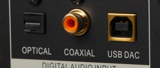
What is the SPDIF out connector on the motherboard and what is it for?
Hi all.
SPDIF out on the motherboard - what it is and what it is used for. Spdif Out is a digital audio transmission protocol. Designed according to the AES3 standard as a version for home use.
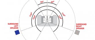
This format supports 5.1 and 7.1 channel surround sound encoding (Dolby, Theater System).
S/PDIF outputs are available on audio equipment, computers and other audio devices.
There are also S/PDIF OUT connectors on motherboards and video cards.
Characteristics:
- asymmetrical connection;
- resistance - 75 Ohm;
- connectors: TTL, RCA, Toslink;
- cables: coaxial, optical;
- SCMC copy protection;
- distance up to 10 meters;
- signal level - 0.5 V.
Transmits signals in the following formats:
- CD, sampling frequency - 44.1 kHz;
- DAT, 48 kHz;
- 16-bit, zero padding;
- 20-bit, with additional data;
- 24-bit, no associated information.
Story
This digital interface format was named after the companies that created the compact disc: Sony and Philips.
S/PDIF was first used in CD drives to connect to converters to produce Hi-Fi sound.
Typically, digital audio was transmitted by compressing it to analog and then restored. At the same time, the sound quality deteriorated.
The S/PDIF standard avoids this procedure and transmits high quality sound without distortion.
Nowadays it is used not only in CD-ROM and DVD players, but also in DAT players, PC sound cards, televisions and home theaters.
Types
- Optical: fiber optic cable, TOSLINK connectors. Most often used in car radios, because The wire is resistant to electrical interference. If earlier specialists connected several wires, now they make do with just “optics”.
- Digital: TTL chips, logic to amplify the output signal. Used in electronic musical instruments and computer sound cards.
- Coaxial: electrical cable, RCA connectors. Used in radio communication channels, television networks, alarm systems, etc.
Instructions
Let's consider a situation where home theater speakers or a TV need to be connected to a computer, but there are no S/PDIF outputs on the system unit.
What is SPDIF out
In general, SPDIF out is a protocol transmitted for a digital audio signal. It is designed according to the AES3 standard. It should be used for household functions. It supports 5.1 and 7.1 audio surround encoding format.
Note! The channel has its own transcript - Sony\Philips Digital Interface.
To put it simply, in order to ensure the correct transmission of stereo sound, it is necessary to ensure speed. The developers, in order not to harm the PC in general, played it safe and created a special channel in the form of SPDIF out. It will help transmit both uncompressed stereo signal and multi-channel audio.
This connector also tells you what frequency, how many channels are connected, whether compression is necessary, and so on. About 1.5 Mbit per second can be invested into the total information flow. By modern standards this is quite small.
The developers came up with this connector to reduce the number of wires required in order to play quality content. They took this weapon as a novelty. After that, a similar channel appeared not only on computers, but also on TV.
If we consider the practical application of this cable, then it is needed in order to connect the speakers to a computer or TV, and then enjoy watching a movie or game.
You can connect various equipment, including speakers that support Dolby Digital or other equipment. The cable is indispensable when regular DVI does not transmit sound. It provides high-quality connection quickly and easily.
You just need to find the correct input on the motherboard and configure the sound transmission method. Moreover, this procedure can take 10 minutes at most. The user will immediately hear the sound without interference, any hissing, and so on.
Method 1: Connect the optical cable to the motherboard
Buy:
- sound card with spdif outputs (coaxial and optical);
- cable;
- connectors.
Steps:
- connect the wire to the sound card;
- find the JSPD, JSPDIF or SPDIF_OUT connector on the motherboard;
- select a connector that matches the location of the pins;
- put the connector on the free end of the cable;
- connect the cable to the spdif connector on the motherboard;
- fix the board on the system unit with the outputs facing outwards;
- connect the optical cable to the Spdif Out output;
- select the sound card as the playback device through the volume menu on the monitor.
OLYMPUS DIGITAL CAMERA
Application areas of various connectors
When a user looks at a computer, TV, or other device, he must understand what cable is used for. It is also worth understanding what types of audio cables there are, for what purposes they are most often used, and much more.
SPDIF out
In fact, this connector is one big name of a type, which is then divided into many others. This type is the most common, but also the oldest. That is why it can only be found in:
- Home cinemas;
- Audio players;
- Car radios;
- Audio players.
This connection goes through the connector that is indicated on the set-top box itself. The connector most often looks like a familiar “tulip”. It is designed for either 75 ohms or 50 ohms. You can also use any other cable that has the same resistance, this option is possible.
Note! SPDIF out is the name of one type. This connector is further divided by wire into coaxial, optical and others.
Digital audio out
This is an optical cable that usually consists of one shell and a core. It is adopted as a standard for TVs such as LG, Samsung and many more. It is required for:
- Conversion from a light signal to an electrical one;
- Its further retransmission, and it passes without distortion;
- Receiving a signal from an incoming device;
- Feedback signal to the device.
Digital audio out works on the principle of a standard audio conductor, but the presence of optical connectors allows you to transmit a signal from the TV to other gadgets using special acoustics. At the same time, the user receives perfect sound. This is partly due to the fact that there is no influence on the fields, a special connection is implemented between devices, and electromagnetic radiation is not generated during transmission.
Coaxial connector
Coaxial cable and connector for it are the rarest type. This is because it involves the use of electricity to transmit a signal. It is a round connector, and you can very rarely find it on any devices. This is due to the fact that optical connectors are much more common than coaxial ones. This was exactly the case in 2022.
You can find it on TVs, AV receivers and amplifiers. If we look at televisions, but they can rarely be found anywhere. Most often, it is these connections that are almost impossible to find.
HDMI
HDMI cables are very common on computers, not TVs. Most often, Blu-ray players, consoles, or channels for satellite or cable are connected, and if the TV supports 4K, then you can easily display this image through this connector.
It has an excellent protocol, which sets it apart from other similar cables. Yes, if coaxial and optical cables support both high resolution and high-quality picture, then they will not be able to withstand the current protocol as required. This is what HDMI connection cables do so well. It is also installed by many developers of popular and even top-end computers and televisions. They broadcast communications immediately, without delays, and there are no connection problems. Only if the number of wires.
RCA
This type of connector is most often called a tulip connector. This is primarily due to the fact that it has such a shape. RCA is often used in audio technology, and the standard is called composite. The cables are similar to standard ones, but they have a compact version.
The wire has 3 connectors. The first is needed in order to transmit a two-channel signal, another one is needed for a mono signal, the final signal is simply needed for broadcasting. It may be noted that this wire can be called a component for the rest. It is often crimped, which makes it even more convenient. Everyone will need this connection.
Hi-Fi
Another interesting cable, which is most often an antenna or directly for home theater. Hi-Fi is more often found in older versions of the device. It's not as popular because compression cables aren't seen that often at the moment. The main thing is that such a connection is preserved afterwards, since it is convenient to write music with it.
Thus, each connector and channel had its own connection. It is important to know all the intricacies of the wires so as not to get into trouble in the future when connecting.
4.5/5 — (21 votes)
Method 2: Connect DVI video card to motherboard
Buy:
- cable from SPDIF to HDMI;
- adapter from DVI to HDMI.
Before purchasing, it is better to make sure that the necessary connectors are available on the motherboard and video card.
Steps:
- connect the wire to the SPDIF connector on the video card;
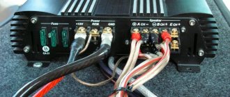
- connect two wires of the cable to the connectors on the motherboard in accordance with the colors: black to GND (“ground”), the second, of a different color, to SPDIF (“signal”);
- connect a DVI-HDMI adapter to the video card;
- turn on the computer and TV;
- in the volume menu settings, select “Playback devices”;
- mark the digital audio source and click OK.
Next to the ground and signal connectors is “5V”.
Usually the very first one in a row, and is often separated from others by an empty pin.
You cannot connect anything to it, otherwise the wire will catch fire!
Nowadays, tricks with connecting internal cables are rarely used, because... modern computers are equipped with Spdif Out outputs.
Moreover, TV and home theater systems are already capable of extracting sound from HDMI channels.
Therefore, the S/PDIF format is used less and less in consumer audio equipment.
In the article we looked at what SPDIF out is on a motherboard. I recommend reading: 10 best programs for diagnosing a computer and laptop
Spdif out on motherboard
S/PDIF (Sony/Philips Digital Interface) is a common and standardized interface designed to transmit digital audio between available components, sound cards, receivers and audio equipment. The connector was originally intended for CD and DVD players capable of playing CDs, with the sole purpose of reducing the number of cables required for high-quality content playback. And after that, manufacturers of home theaters, televisions and other equipment adopted the new product. Moreover, both because of its compactness (a single fiber-optic cable that is resistant to interference can replace a whole bunch of connectors) and because of its quality.
Important!! S/PDIF perfectly conveys surround sound and allows you to enjoy every second of the track or movie being played.
- Home page
- Stereo system
- S/PDIF digital interface and how it works
Digital audio sources
- CD player
- SACD player
- CD transport
- Processors (DAC-DAC)
- How to choose a digital source?
- What to pay attention to when listening?
- S/PDIF digital interface and how it works
Vinyl players
- Propulsion mechanisms
- Tonearms
- Pickup heads
- How to choose an LP player?
- What to pay attention to when listening?
- Player setup
All about vinyl
Digital sound sources Digital interface S/PDIF and how it works Digital output.
A socket on all CD transports and some CD players that provides access to a digital data stream. Using a digital output, a CD transport can supply information to a separate digital processor via the S/PDIF interface (Sony/Philips Digital Interface Format). It is named after the two companies that invented the compact disc. The S/PDIF digital interface is a standard format for transmitting digital audio, primarily between CD transport and a digital processor. The S/PDIF signal can be carried through different types of connectors and cables, such as optical ST or coaxial (discussed later in this chapter). All consumer digital audio equipment - transports, digital processors and digital recording devices - uses the S/PDIF interface. The professional version of S/PDIF is called the AES/EBU interface (Audio Engineering Society/European Broadcast Union, or the Society of Audio Engineers/European Broadcasting Union - the organizations that standardized this interface). It is sometimes used in consumer digital audio equipment.
Jitter
is temporary errors in the clock generator that sets the moments at which the digital samples of a CD are converted into music. Jitter also worsens the sense of space, reducing soundstage depth and blurring musical images. The feeling of transparency of the air between you and the performer disappears, the space seems to be filled with haze. The main source of jitter in digital audio reproduction is the interface connecting the CD transport to the digital processor. Get rid of the digital interface that a CD player inherently lacks, and you eliminate the main driver of jitter. For this reason, single-body CD players, all other things being equal, have a significant superiority in sound quality over component equipment. The S/PDIF signal contains audio data from both audio channels as well as a synchronization signal, also called a clock. These clock pulses are restored by the digital processor, so that the transport and processor operate on the same time basis. The "Lock" indicator or sample rate indicator on the front panel of many digital processors indicates that the clock has been restored and the two components are in sync, i.e. their clock frequencies are the same. The S/PDIF interface data stream carries not only audio information, but also service information, including a number of CD subcodes. They contain information about the sampling frequency, the use of predistortion, as well as information about whether the signal belongs to the professional AES/EBU interface or the S/PDIF interface for consumer equipment. The subcode data also includes all track numbers and timing information displayed by the CD player or transport indicator. Audio data and subcode information are combined into 32-bit sukers. Each subframe begins with a preamble, a four-bit sync group that violates the rules of biphase coding. The preamble acts as a synchronization signal indicating the start of a new subframe. The preamble is followed by four bits of auxiliary information and 20 bits of audio information. If sixteen-bit audio information is transmitted, then the additional four bits are not used (replaced with zeros during encoding). The four-bit additional data area can be used to accommodate audio data, increasing the total word length of audio data to 24 bits. An additional four bits (audio sample validity, user data bit, audio channel status, and subframe parity) complete the subframe. The left and right audio channel subframes are identified by slightly different preambles. In a single stream of bits they are transmitted alternately. Blocks of length 192 bits are formed from subframes. At a sampling rate of 44.1 kHz, the total bit rate is 2.8224 million bits per second.
What is S/PDIF OUT on the motherboard
Accordingly, S/PDIF OUT is a connector often found on computer motherboards with the sole purpose of transmitting a high-quality digital audio signal between different devices and components without the mandatory and sometimes inevitable procedure of converting the information into an analog signal.
Essentially, manufacturers are offering to complement the PC entertainment experience with third-party equipment, such as speakers that support 5.1 Dolby Digital or home theater for a complete experience. In some cases, S/PDIF is indispensable if the signal from the video card cannot be output using HDMI, and DVI does not transmit sound.
In this case, it is enough to buy additional speakers with an adapter, find the desired output on the motherboard (you will have to open the cover of the system unit in any case; in some cases it is much easier to buy an external audio card that can perform the same task, but much better), and then - configure the sound transmission method.
The procedure will take about 5-10 minutes, and the result will immediately impress - cutting-edge quality without interference, long response time or strange hissing, known from low-quality equipment.
In general, S/PDIF is an irreplaceable thing, although it has partially lost its former position. Although modern motherboards support a similar interface, there are fewer and fewer enthusiasts turning to S/PDIF. And it's not that the world has stopped worrying about sound quality. And in the number of additional solutions and outputs that offer the same functions, but without additional settings.
How to Use the Optical (S/PDIF) Port on Windows 10
The optical output port on a PC is a mystery to many. It sits at the back of your PC and emits a constant red laser beam, regardless of whether anything is connected to it or not. It looks like you should be connecting something to this, but what? The logical answer is an optical audio cable, and here's a good look at how to get it to work, with the caveat that it's become quite clunky to use on Windows 10 in recent years.
Simple interface module Spdif to I2S for DAC on AK4113
It was decided to update the AH-D3 DAC project and divide it into 2 separate devices.
As a result, I would like to present to your attention a simple SPDIF -> I2S converter board based on AK4113, which can be used in conjunction with the AH-D1 / AH-D5 / AH-D5.5 / AH-D6 line of DACs with the latter switching to slave mode. First of all, the module is recommended for use with simple budget designs such as AH-D1 and AH-D3.1. And also for those who require an SPDIF interface or simply as a temporary solution for testing the DAC. In any case, the asynchronous USB interface based on Amanero and others is the main interface module option I recommend, as it allows you to get the best level of sound quality.
- The board has two inputs, optical and coaxial. Switching between inputs is carried out using a switch, see J4.
- The board can be powered either from an external 5V power supply or from a 3.3V isolator power line from the I2S connector (provided in my AH-D1 / AH-D5 / AH-D5.5 / AH-D6 DACs).
- The i2s output port has a pinout similar to Lynx DACs.
- The output data format can be set using jumpers (J5 CINFIG).
SPDIF receiver circuit on ak4113
Printed circuit board
The board is made on a piece of PCB measuring 40x50mm.
I2S connector (J2)
The AH-T1 module is fully compatible with my line of DACs. The main requirement is to use them in slave mode, since the clock signal is supplied from the module to the DAC board; the design does not provide for working with an external clock signal.
The i2s connector has Lynx Audio pinout. Contacts 2, 4, 6, 8 - ground. Pin 9 - +3.3V power supply, supplied from the DAC side.
Pins 1, 3, 5, 7 - i2s bus signals:
| Format | Pin 1 | Pin 3 | Pin 5 | Pin 7 |
| PCM | BCK OUT | SDATA OUT | LRCK OUT | MCLK OUT |
Pin 10 - mute signal. Low logical level - normal operation, high logical level - mute, muting the DAC.
CONTROL jack
The 5x2 connector is used for compatibility with my DAC designs, but some of the pins are essentially not used, playing the role of plugs.
Pin 1 is not connected, since the clock signal is supplied to the DAC from the AH-T1 module (for the DAC this is a signal to turn on the desired master clock generator; for the slave mode, switching generators on the DAC board makes no sense)
Pin 3 is the Connect signal. When power is applied to the module board, it always sets the level to “0”, which corresponds to the active operating mode of the DAC.
Pin 7 - always transmits level “1” to the DAC, which signals the DAC about the presence of a PCM stream, DSD is not supported (for the DAC pin 7 the signal switches PCM/DSD).
Pins 5, 9 - Levels are output to them depending on the current sampling frequency:
| Sampling frequency | Pin 9 | Pin 5 |
| 44.1kHz/48.0kHz | 0 | 0 |
| 88.2kHz/96.0kHz | 0 | 1 |
May be useful for some DACs where the interpolation coefficient must be set manually, such as the AD1853.
All my AH-Dx DACs, when working with the AH-T1 module, are suggested to be used in Auto Setting Mode, ACKS bit = “1” (see the configuration of the CONFIG connector in the description of the DACs), in this case pins 5, 9 have no values, since the sampling frequency is determined automatically.
Active input selection
Connector J4 is used to select the active optical / coaxial input; for this it is proposed to use a simple 2-position switch.
Indication
For indication, the board has connector J1, to which the power-on and mute mode signaling signals are output.
Selecting Output Format
By default, all signal pins of the connector are pulled to level “1”.
The module allows you to set the output format I2S-24/LJ-24/RJ-16/RJ-18 according to Table 16 from the documentation for ak4113.
All my designs use the I2S format, the correct configuration is in the photo (green table line)
Link to order PCBs in China
The BOM is available for download for registered users.
How they connected SPDIF_OUT to me, and how it ended.
How they connected SPDIF_OUT to me, and how it ended.
Post by alexs1973 » 05/28/2009 9:32 am
So, I didn’t have the cord, I brought the computer to the store (warranty, seals), I said, man, just put it right for me, don’t mix up the ends, he poked it with a tester, he said everything is ready. I bring the computer home, connect everything, plug in the power, and oh gods, smoke comes out of the computer! I found a book about my mother, look, and there are two of the necessary contacts, they have a little to the left of the brother, there is another contact, only the power on it is 5V. Well, I think it’s fucked up, apparently they connected one contact to it. We opened it up in the store, and there it is, the red contact is for power, the wire is burnt into rubbish, otherwise there is no visible damage. We removed the wires and embers, turned on the computer, it won’t boot, it says disk error. They say come back tomorrow, it was in the evening, before closing. I come in the morning, they look so happy to me, nothing burned, everything is plowing, and I, why didn’t it load yesterday? Why did you switch in the BIOS, boot to the second drive (before assembling the computer, I brought them an old screw and asked them to insert a second one), I say, what does this have to do with the old screw, there is a 70 gig file on it, there is no system, and I didn’t touch it The BIOS, they say, no, they probably switched it, and the computer tried to boot from it. BULLSHIT. In short, everything works, look, the string, as it turned out, was also confused with colors, that is, red SPDIF_OUT turned out to be GND. I brought it home, plugged it in, there was sound, but no other audio devices appeared, and the SPDIF_OUT volume control was not active. In short, this thing is strange, this SPDIF_OUT, it’s different for everyone, it probably depends on the mother-video connection. Now about the sad thing, after working on the computer at home for three hours, watching movies from an old screw, there is sound everywhere, the video camera is working, nothing seems to have burned out, I turn off the computer for a couple of hours. After turning on the black screen, press F1 for a long time, the system boots, and oops the old screw has disappeared. Subsequent reboots and viewing did not bring any results in the BIOS, there is no screw. They checked it at the store and they say the reading head has fallen off. Now I’m thinking, maybe it flew, that the cord was not initially connected correctly to the power supply, and in general, whatever else could have flown or will fly. What do you think, tell HELP.