Three-way speaker systems, consisting of three speakers, are the most successful solution for high-quality sound reproduction. They use three types of sound heads. They differ in size, design features and reproduced frequency band. To separate the entire frequency range produced by the low-frequency amplifier, bandpass crossover filters are used. They use capacitors, chokes and, less commonly, resistors.
It is very simple to make a filter for a low-frequency speaker with your own hands. The main element of the device is inductance or choke. The coil is connected in series with the subwoofer.
Subwoofer Filter
A low-pass filter made of an inductor and a large capacitor is called a second-order Butterworth circuit. It provides a roll-off of frequencies above the cutoff frequency of up to 12 dB per octave. The scheme works as follows. The inductance in the LC circuit acts as a variable resistor. Its resistance is directly proportional to frequency and increases with increasing range. Therefore, high frequencies practically do not reach the woofer. A capacitor also performs the same function. Its resistance is inversely proportional to the frequency and it is connected in parallel with the loudspeaker.
Since the device circuit must pass low frequencies well and cut off high frequencies, the capacitors of such a device have a large capacity. A passive filter for a speaker can be made using a more complex circuit. If you connect two Butterworth circuits in series, you get a fourth-order device consisting of two inductors and two capacitors. It provides a low-frequency loudspeaker roll-off of 24 decibels per octave.
In order to equalize the frequency response and more accurately match the Butterworth circuit and the speaker, a resistor with a small resistance is connected between the inductor and the capacitor. For this purpose it is better to use wirewound resistors.
CONTENT
In multi-band speakers, heads designed to reproduce different parts of the frequency range are switched on through so-called crossover filters. Their purpose is to pass voltage of only the required frequencies to each head.
These filters are distinguished by the steepness of their rolloff beyond the highest or lowest cutoff frequency. Typically, filters with a slope of 6, 12 or 18 dB per octave are used.
According to the scheme, they are divided into filters for two-way and three-way speakers.
The initial data for the calculation are the crossover frequency and the head resistance in the filter's operating band. In Fig. 89, a, b, c show filter circuits with roll-off slopes of 6, 12 and 18 dB/octave, respectively. The upper part of each figure shows a filter diagram for a two-way speaker, and the bottom part for a three-way speaker.
[/td]
Each figure also shows a formula for determining the elements of these filters.
Rice. 89. Schemes of isolation filters
Inductive and resistive capacitances are given in Farads, Henrys and Ohms respectively. Filter capacitors are selected from a range of industrially produced products.
The most suitable capacitors for isolation filters are MBGO type capacitors whose parameters are given in Appendix 6.
As for inductors, they are made by winding without an iron core to avoid distortion due to magnetization reversal.
A practically optimal design in terms of the maximum ratio of the coil's inductance to its active resistance is obtained when the internal diameter of the cylindrical winding is twice its height L, and the outer diameter is 4 times greater than h and 2 times the internal diameter. Under these conditions, the value of h is (√L/R)/0.866 mm (L, µH, R, Ohm), wire length l = 187.3√Lh, number of turns N — 19.88 √L/h, — wire diameter (without insulation) d=0.84●h/√N, wire mass m = (h3/21.4)●10 3 kg.
DIY speaker filters
Making a filter for a speaker is not at all difficult. It consists of only two elements - a capacitor and an inductor. The easiest way to calculate the parameters of radioelements for a second-order low-frequency passive circuit is to use an online calculator. There you can set the desired cutoff level and acoustic head resistance. The program will display the required capacitance of the capacitor and inductance of the coil. For example, the cutoff level is 150 Hz and the speaker impedance is 4 ohms. The calculator will give the following values:
- Capacitor capacity – 187 µF
- Coil inductance – 6.003 mH
The required capacity can be obtained from parallel-connected capacitors K78-34, which are specially designed for operation in acoustic systems. In addition, there is an updated line of capacitors of a similar type. This is KZKWhiteLine. As inexpensive analogues, radio amateurs often use capacitors such as MBGO or MBGP.
A 6 mH inductor coil is wound on a mandrel with a diameter of 1 cm and a length of 6 cm. Since the coil does not have a magnetic core, a cylinder of any material can be used as a bobbin, on which cheeks must be made for ease of winding. For winding, copper wire of the PEL type with a diameter of 1 mm is used. The length of the wire is 84 meters. Winding must be done turn to turn.
Three-way loudspeaker crossover filters
In order to reduce intermodulation distortion during sound reproduction, the loudspeakers of Hi-Fi systems are composed of low-frequency, mid-frequency and high-frequency dynamic heads. They are connected to the amplifier outputs through crossover filters, which are combinations of LC low-pass and high-pass filters.
Below is a method for calculating a three-band crossover filter using the most common scheme.
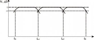
The frequency response of the crossover filter of a three-way loudspeaker is shown in general form in Fig. 1. Here: N is the relative voltage level on the voice coils of the heads: fн and fв are the lower and upper limiting frequencies of the band reproduced by the loudspeaker; fр1 and fр2 are crossover frequencies.
Ideally, the output power at the crossover frequencies should be distributed equally between the two heads. This condition is met if, at the crossover frequency, the relative voltage level supplied to the corresponding head decreases by 3 dB compared to the level in the middle part of its operating frequency band.
Crossover frequencies should be chosen outside the area of greatest sensitivity of the ear (1... 3 kHz). If this condition is not met, due to the difference in the phases of the oscillations emitted by the two heads at the interface frequency simultaneously, a “split” sound may be noticeable. The first crossover frequency usually lies in the frequency range 400... 800 Hz, and the second - 4... 6 kHz. In this case, the low-frequency head will reproduce frequencies in the range fн…fp1. mid-frequency - in the range fp1...fр2 and high-frequency - in the range fр2...fв.
One of the common variants of the electrical circuit diagram of a three-way loudspeaker is shown in Fig. 2. Here: B1 is a low-frequency dynamic head connected to the amplifier output through a low-pass filter L1C1; B2 is a mid-frequency head connected to the amplifier output through a bandpass filter formed by high-pass filters C2L3 and low-pass filters L2C3. The signal is fed to the high-frequency head B3 through high-pass filters C2L3 and C4L4.
The capacitances of capacitors and inductances of coils are calculated based on the nominal resistance of the loudspeaker heads. Since the nominal resistances of the heads and the nominal capacitances of the capacitors form a series of discrete values, and the crossover frequencies can vary within wide limits, it is convenient to carry out the calculation in this sequence. Having specified the nominal resistance of the heads, select the capacitances of the capacitors from a number of nominal capacitances (or the total capacitance of several capacitors from this row) such that the resulting crossover frequency falls within the frequency intervals indicated above.
In isolation filters, metal-paper capacitors of the MBGO, MBGP and MBM types are usually used with a permissible deviation from the nominal capacitance of no more than ± 10%. The most suitable capacitor ratings for use in filters are given in Table 1.
| Capacitor type | Capacity, uF |
| MBM MBGO, MVGP MBGP MBGO | 0,6 1; 2; 4; 10 15; 26 20; 30 |
The capacitances of filter capacitors C1...C4 for various head resistances and the corresponding crossover frequencies are given in Table 2.
| Zg,0m | 4.0 | 4.5 | 5.0 | 6.5 | 8.0 | 12,5 | 15 |
| C1, C2, uf | 40 | 30 | 30 | 20 | 20 | 15 | |
| fp1, Hz | 700 | 840 | 790 | 580 | 700 | — | 520 |
| C3, C4, ICF | 5 | 5 | 4 | 4 | 3 | 2 | 1 .5 |
| fр2,Hz | 5.8 | 5.2 | 5. | 4,4 | 4.8 | 4,6 | 5.4 |
It is easy to see that all capacitance values can either be directly taken from the nominal series of capacitances. or obtained by parallel connection of no more than two capacitors (see Table 1).
After the capacitor capacitances are selected, the inductance of the coils in millihenries is determined using the formulas:
In both formulas: Zg-in ohms; fp1, fр2 - in hertz.
Since the impedance of the head is a frequency-dependent quantity, the nominal resistance Zg indicated in the head’s passport is usually taken for calculation; it corresponds to the minimum value of the impedance of the head in the frequency range above the main resonance frequency to the upper limit frequency of the operating band. It should be borne in mind that the actual nominal resistance of different head samples of the same type may differ from the rated value by ±20%.
In some cases, radio amateurs have to use existing dynamic heads with a nominal impedance that differs from the nominal impedances of the low-frequency and high-frequency heads as high-frequency heads. In this case, resistance matching is carried out by connecting high-frequency head B3 and capacitor C4 to different terminals of coil L4 (Fig. 2), i.e., this filter coil simultaneously plays the role of a matching autotransformer. The coils can be wound on round wooden, plastic or cardboard frames with getinax cheeks. The lower cheek should be made square; This makes it convenient to attach it to the base - the getinax board, on which capacitors and coils are mounted. The board is secured with screws to the bottom of the speaker box. To avoid additional nonlinear distortions, the coils must be made without cores made of magnetic materials.
Filter calculation example
As a low-frequency loudspeaker head, a 6GD-2 dynamic head is used, the nominal impedance of which is Zg = 8 Ohms. as a mid-frequency - 4GD-4 with the same value of Zg and as a high-frequency - ZGD-15, for which Zg = 6.5 Ohm. According to table. 2 with Zg=8 Ohm and capacitance C1=C2=20 µF fp1=700 Hz, and with capacitance C3=C4=3 µF fp2=4.8 kHz. In the filter, you can use MBGO capacitors with standard capacitances (C3 and C4 are made up of two capacitors).
Using the above formulas we find: L1=L3=2.56 mg; L2=L4=0.375 mH (for autotransformer L4 this is the inductance value between pins 1-3).
Autotransformer transformation ratio
In Fig. Figure 3 shows the dependence of the voltage level on the voice coils of the heads on the frequency for a three-way system corresponding to the calculation example. The amplitude-frequency characteristics of the low-frequency, mid-frequency and high-frequency regions of the filter are designated LF, MF and HF, respectively. At crossover frequencies, the filter attenuation is 3.5 dB (with a recommended attenuation of 3 dB).
rice. 3
The deviation is explained by the difference in the impedances of the heads and capacitors of the capacitors from the given (nominal) values and the inductances of the coils from those obtained by calculation. The slope of the LF and MF curves is 9 dB per octave and the HF curve is 11 dB per octave. The HF curve corresponds to the uncoordinated activation of loudspeaker 1 GD-3 (at points 1-3). As you can see, in this case the filter introduces additional frequency distortion.
Editor's note . In the given calculation method, it is assumed that the average sound pressure at the same supplied electrical power for all heads has approximately the same value. If the sound pressure created by any head is noticeably higher, then in order to equalize the frequency response of the loudspeaker according to the sound pressure, it is recommended to connect this head to the filter through a voltage divider, the input impedance of which should be equal to the nominal resistance of the heads accepted in the calculation.
(RADIO N 9, 1977, p. 37-38)
Example
Determine the data of a coil with an inductance of 3.37 mH of an isolation filter loaded with a head with a resistance of 15 Ohms.
We choose the active resistance of the calculated coil equal to 5% of the head resistance. This ratio can be considered quite acceptable. Then R = 0.05•15 = 0.75 Ohm, whence L/R = 3.37•103/0.75 = 4500. Winding height h = √4500/0.866 = 24.5 mm, wire length l = 187 ,3•√3.37•103/24.5 = 5.35•104=53.5 m, number of turns N = 19.88•√3.37•103/24.5 = 233 turns, wire diameter d = 0.84•24.5/√233 = 1.35 mm, wire mass m = (24.53/21.4)•103 = 0.69 kg.
Naturally, the resulting numbers must be rounded, and first of all the wire diameter, to the nearest standardized diameter. The inductance is finally adjusted by measuring on the bridge, unwinding several turns of the winding, wound with a slight excess in the number of turns compared to the calculated one. The spools can be wound on plastic, wood or cardboard frames.
Frameless winding is also used (Fig. 90), in order to prevent the coil from falling apart, the turns after winding each layer are coated with BF-4 glue.
Rice. 90. Scheme of frameless coil winding
If possible, to polymerize the glue, the coil is baked in a thermostat at a temperature of 140 - 160 ° C for 1 hour.
If this is not possible, then the coil should be dried at room temperature for 24 hours. Sometimes the wire, which is preferred as PEL, is coated with some kind of oil.
Then, before winding or during the winding process, the wire must be wiped with a cotton swab moistened with a mixture of 50% alcohol and 50% gasoline or, in extreme cases, pure gasoline. The assembled and mounted filter, i.e. its capacitors and coils, is placed on a shelf mounted inside the speaker housing. Of course, all electrical connections must be well soldered to avoid rustling and crackling noises that may occur due to poor contacts.
Back to the main page … | |