How to make speakers with an isobaric subwoofer for a computer yourself.
There is a good book written by S.V. Gaponenko, called DIY acoustic systems. The book is written in a fairly accessible and simple language, but it is not boring; there are clear examples and explanations.
In it you can see information on making a homemade calculation for creating columns. Anyone who has already dealt with similar things may disagree with the author in some ways, but overall the book is recommended for reading.
There are more boring books on this topic, for example, S. Bat, called amateur loudspeakers. Let's look at how to make a subwoofer for a computer yourself at a small size.
Tests.
Since I do not have a measuring room, I had to remove (the frequency response) both from homemade speakers and from the industrial speaker “S-30” so that I could have at least some kind of reference point.
This is the frequency response of “White Noise” taken from the “S-30”.
The same goes for a homemade product with one full-range speaker.
Frequency response of a homemade two-way speaker.
To the ear, single-way speakers sound much louder than the S-30, and two-way speakers sound a little better in high frequencies. Of course, both are inferior to the S-30 in low frequencies. Actually, this is confirmed by the graphs.
To remove the hump in the frequency response around 400Hz, which is unpleasant to the ear, I had to use the audio card’s equalizer.
This is what happened after correcting the two-way speaker.
The disadvantages of “plumbing” speakers include the relatively small maximum permissible power, with relatively large dimensions. But this can be attributed to the costs of the budget decision.
As for comparing the sound quality with Chinese plastic speakers, the latter have already gone looking for another listener.
If anyone wants to repeat this design, be careful when connecting speakers to a high-power VLF. It is very easy to damage a speaker designed for use in open speakers, especially at low frequencies.
During testing, I used a 30-watt amplifier and, due to carelessness, I destroyed the coil of one of the heads, produced in 1978 (apparently some of the turns had come unglued)
Another improvement
One of my laptops did not have a standard equalizer, and I have long been planning to equalize the frequency response of these speakers by replacing the tweeters. When I removed these Jericho pipes from the wall, I found too much dust inside.
So, along with replacing the tweeters, I also added dust collectors that cover the entire speakers.
Construction and details.
In this speaker system, the signal to the high-frequency speaker is supplied through current-carrying rods, with which it is attached to the low-frequency speaker. The rods are made of PEV-2 copper wire with a diameter of 1.5 mm. The length of each piece is 65mm. At the junction with the current-carrying petals, the rod is cleaned of varnish and tinned.
To prevent the signal from shorting to the speaker housing, insulating bushings and washers are used.
Mounting unit for the rod to the HF head.
Mounting unit for the rod and bracket to the woofer head.
The picture shows the fasteners and parts used to assemble the speaker.
The filter coil is wound with copper insulated wire PEL-2 with a diameter of 1 mm. on the boss from self-adhesive tape (scotch tape) and has 95 turns, wound in four layers. When winding, the layers were secured with BF-4 glue.
The capacitor and coil are attached to a bracket, which in turn is attached to the speakers.
The bracket is made of a steel strip 8mm wide, 1mm cross-section according to this drawing. The dotted line indicates bending points.
This is what the assembled speaker assembly looks like. Centering of the low-frequency speaker in the groove of the rubber seal is carried out by two insulating and two steel bushings with a diameter of 8 mm.
Spring washers (grower) were used as locking elements when assembling the speakers. Instead, you can use any nitro paint or BF glue.
Simple malfunctions of computer speakers and their repair
Almost any malfunction of computer speakers can be repaired by a semi-skilled electrician who knows how to use a tester (multimeter).
Computer speaker repair
Lack of sound from the speakers can be caused by such simple faults as a broken wire in the amplifier's 3-pin plug, a broken power cord, a blown fuse, a broken wire from the amplifier to the speakers, or a failure of the speakers themselves.
The functionality of the speakers can be checked by picking up the 3-pin input plug; then, with a working sound system, the 50 Hz background will be clearly audible from both speakers. To check the left and right channels of the audio system separately, you need to pick up a thin screwdriver by the metal and take turns touching the contacts of the left and right channels on the three-pin input plug.
Thus, it is possible to determine the performance of each system amplifier separately. The amplifier can be powered directly from the computer via a USB connector or via a 220 V network. The 5 V voltage at the end of the USB cable can be checked with a tester. If the power is supplied via 220 V, then the 220 V voltage on the primary winding of the transformer and the output voltage on the secondary winding are checked.
External view of a computer speaker amplifier. Amplifier chip under the radiator
If there is no voltage on the secondary winding, then the resistance of the primary winding on the transformer is checked, having first disconnected the speakers from the network. If there is no resistance, then the transformer needs to be replaced. The resistance of the primary winding can vary from hundreds of Ohms to kOhms, depending on the power of the transformer.
You can check the speakers for functionality using a tester. In this case, if the speakers are working properly, a slight click should be heard and the tester will show a resistance of 4 or 8 ohms. Without a tester, the speakers are checked using a 1.5 V battery. Its output is applied to the speaker contacts, as a result of which we hear a noticeable click and see the movement of the speaker cone.
Interesting facts and useful tips
A portable speaker may be needed in many circumstances: outdoor recreation, cycling, vacationing in the country, etc.
Now I will tell you one of the options for making it. What you will need:
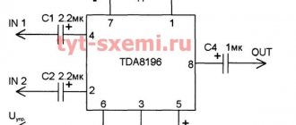
- TDA2003 microcircuit or its analogues, K174UN14 - domestic analogue (price approximately 0.3 $) - capacitors: a) 10 mf 16v - 1 pc. b) 100 mf 16 v - 2 pcs. c)0.1 mf 16v - 1 pc. d) 470 mf 16 v - 1 pc. (you can also use capacitors of more than 16v, but as a rule they consume more energy) - resistors: a) 10 ohm - 1 pc b) 1 om - 1 pc c) 1 kom - 1 pc - speaker (more on that later) - soldering iron, solder.
1. We make a list of the components we need
and go to the nearest radio store, there we will buy all the parts and assemble our MONO amplifier. I suggest choosing a mono amplifier for several reasons: 1) less energy consumption compared to a stereo amplifier. 2) from a portable speaker, in my opinion, such things as sound quality, volume, battery life are required.
After we have purchased all the components we need, we can proceed directly to assembling the amplifier. (diagram below) I have tested this circuit more than once, it has good sound quality, and it is quite simple to manufacture and does not require configuration. —————————————————————————————— It is recommended to assemble the amplifier on a printed circuit board, but if you don’t have the skills to make it, you can assemble it on cardboard (just pierce holes, insert parts into them and connect according to the diagram)
3. After we have safely completed the assembly, we need to take care of cooling the TDA2003
. To do this, I recommend using a small heatsink that is bolted to the hole on the microcircuit; you can also use thermal paste for better heat transfer.
4. Now we need to take care of nutrition
of our amplifier, here are its power ranges - from 8 to 16 V. (recommended 14.4 c.). I used 3 batteries from mobile phones, which in total produced 11.1 V. which is quite enough to power our amplifier. You can also use AAA or AA batteries, we will need 8 pcs. , which will give a total of 12V.
5. Speaker selection.
This amplifier is suitable for 2, 4, 8 ohm speakers. 2 ohm 10 W 4 ohm 5 W 8 ohm 2.5 W but from my own experience I will say that I connected a car (4 ohm) PIONEER speaker at 30 W, and it played very loudly and with high quality
5. For the base of the body
For our portable speaker, we can take the case from a broken computer speaker, but for high-quality sound we need to make a wooden case ourselves. It is made from 5-7-layer plywood, in such a case the speaker will have more low frequencies and clear sound at high frequencies.
Step-by-step instruction
To make a column, you need to prepare a workplace. It must comply with basic safety requirements:
- Have the lighting and ventilation recommended by GOST and TU.
- There should be no flammable objects or liquids nearby.
- It is advisable to have a grounding wire at the site of assembly and testing of the product.
At the time of starting work, it is necessary to make all calculations and complete diagrams and drawings.
Housing assembly
Order of conduct:
- The column details are drawn on a sheet of chipboard. An allowance is given for the obtained calculated data for the thickness of the material.
- The parts are cut out with a hacksaw.
- The front panel marks the location for installing the speakers. The proposed holes are outlined with a compass or outlined using a template. They must be round and exactly fit the size of the emitters.
- The holes for the emitters are cut out with a hand jigsaw (or a similar electrical device). The outer edges are carefully sanded with sandpaper.
- The top, side and bottom panels are assembled. The joints are smeared with PVA glue, 2-3 self-tapping screws are screwed in at each joint. They must be screwed in at right angles.
- The housing must be sealed, so all seams must be coated with adhesive after screwing in the screws.
- If you plan to make the back wall removable, then you need to stick a seal around its perimeter.
- Emitters are mounted on the front panel on the inside and decorative grilles on top. The mounted panel is installed in its place in the same way as assembling the frame (glue + self-tapping screws).
Power switch and connector
They are connected by soldering to the battery case along with the protection board.
In order for everything to be done correctly, a number of conditions must be met when installing the power connector:
- The right contact can be bent or removed.
- The average is positive.
- The left one should go to ground.
- You should insert the included charger into the connector and check the voltage with a multimeter. This will ensure the correct polarity of the connector pins.
- Then it is soldered into the protection circuit.
Connecting to a Bluetooth module
Power is supplied to it through a switch. Since there is only one speaker, stereo sound on the module is reduced to one channel. In this case, resistors must be inserted into the circuit (one per channel). If you connect one wire, then a resistor is not needed. Sound control will be carried out from the transmitting device (smartphone, tablet, etc.).
Battery connection
There are various options for using autonomous power sources, but one of the simpler and more reliable is the use of inexpensive rechargeable batteries.
The protection board is used to prevent force majeure circumstances:
- short circuit;
- recharge;
- excessive discharge, etc.
This board is a must when using lithium-ion batteries.
For ease of assembly and operation of the battery pack, batteries (3 pcs.) should be placed in a case.
Checking status
Before mounting the assembled circuit in the bass reflex housing, it is necessary to check its functionality.
Procedure:
- To do this, insert batteries into the case and press the switch.
- In this case, the Bluetooth module should emit a characteristic squeak, indicating that it is connected.
- After a sound signal, the module is paired with the smartphone.
- If everything is done correctly, you can turn on the music.
After a positive check of the device, the assembled circuit is mounted in the speaker housing.
Preparing tools
So, during the work we will need the following materials and tools:
- screwdriver;
- sheet of chipboard or MDF (for making the speaker system housing);
- marker;
- jigsaw;
- 400 W PC power supply;
- radio;
- Bulgarian;
- a pair of acoustic speakers;
- furniture screws and self-tapping screws;
- sealant (it is best to use silicone based);
- voltmeter and glue.
Before assembling the speaker system, first check the operation of the radio and find out whether it can be powered or not. It is also necessary to test the speakers for sound quality. After this, you can safely begin manufacturing the housing and other elements of the speaker system.
What will be needed for production?
In addition to the material from which the housing is made, an active speaker requires:
- one broadband, or 2-3 more narrowband speakers;
- ready-made or homemade power supply;
- ready-made or homemade audio power amplifier;
- regular wire or cable;
- winding wire;
- plastic pipe of suitable diameter;
- rosin, solder and soldering flux;
- adhesive sealant;
- epoxy glue or furniture corners.
Tools needed:
- pliers;
- side cutters;
- flat and shaped screwdrivers (a set of screwdrivers is best);
- wood hacksaw;
- file or chisel;
- hand drill and set of drills.
The functions of a drill are also performed by a screwdriver turned on at high speeds.
The most interesting videos on Youtube
Other articles devoted to the construction of this ULF.
How to calculate and wind a low-frequency power transformer for a ULF power supply? FAQ.
Technical specifications and assembly drawing for a homemade amplifier. ULF, part 2.
Power supply for low frequency amplifier from available parts. ULF, part 3.
Electronic volume, stereo and tone control unit. ULF, part 4.
Block of low frequency final amplifiers. ULF, part 5.
Simple technologies for processing plastic and metal. ULF, part 6.
Final assembly, adjustment and testing. ULF, part 7.
At first I thought it would be nice to write a manual for making an amplifier. But it seemed to me that building an amplifier on a modern element base is a little easier than manufacturing speaker systems. Therefore, I decided to split the article into two parts and first make a simple stereo acoustic system from the most available parts.
Next we will talk about simple speakers and an amplifier, which, nevertheless, could give a head start to the squalor that is provided with a desktop computer.
You know, there are such plastic active acoustic systems (hereinafter referred to as “AS”), one of which already has a built-in amplifier on a chip in a DIP8 package. I also received this kit with my first computer. It is simply impossible to use these speakers without first removing low and mid frequencies in the audio card's equalizer. But I would like, on the contrary, to be able to raise high and low frequencies when listening to music or watching movies.
But let's get back to our homemade products.
I made homemade speakers only twice and both times in my youth. Even then, I was sorely lacking low frequencies, and my first speaker was, as it would now be called, a subwoofer.
To implement the project, I made only the front panel, and as the body I used the lower compartment of the bedside table from the TV with a volume of fifty liters. Two 4GD-28 speakers were installed diagonally and draped with radio fabric. As a low-pass filter, I used a spool of thread No. 10 with a wire of unknown cross-section wound around it. I made holes in the back wall of the nightstand. In the early seventies, this design impressed my friends.
Now you can also use this experience if you add something similar to the existing plastic speakers. Believe me, such a simple design will easily “make” any subwoofer from a budget home theater and other Chinese crafts.
But this time I decided to make a traditional pair of speakers, since there was no more free space left in the furniture.
The idea to use sewer pipes as a housing for the column came by chance when I saw an article on the Internet, the author of which, apparently taking inspiration from Home Depot, used similar pipes to make a wind generator propeller.
Since I had never heard how a round speaker works, before buying sewer pipes, I glued a pipe of the required diameter from cardboard. I used three-liter glass canning jars as a template.
The very first activation of the speaker layout gave a positive result, and I boldly went to the store.
Checking the amplifier and speaker power supply
The procedure for identifying speaker malfunctions may vary. I use the following sequence for troubleshooting audio systems. First of all, I check the input from the amplifier plug, that is, by touching the plug contacts with my hands. If there is no background, I check the amplifier's power supply, starting with its output. Usually a 12 V voltage stabilizer is installed in the power supply.
View of a standard amplifier chip and other elements
By its marking you can find the pinout of the stabilizer terminals and check the output voltage. If the input voltage is about 18 V, and the output voltage is 12 V, then we next check the operation of the amplifier. When the input voltage is 18 V, but the output is 12 V, then we definitely change the stabilizer to the same one or its analogue. When everything is in order with the power supply, we move on to checking the amplifier.
Audio systems use various types of amplifiers on microcircuits installed on cooling radiators. The size of the radiator depends on the power of the amplifiers. We also find the markings of the amplifier microcircuit, enter the type of microcircuit in a search engine and find its characteristics and pinout. We determine the input contacts of the microcircuit by the pinout and its diagram, then touch them with a thin metal probe and with our hands.
Circuit diagram of a simple USB powered speaker
So we check the left and right channels. A strong background should appear. In this case, the volume control is at the maximum level. One of the channels does not work - we check its speaker and if it works, we change the microcircuit. We also check the supply voltage on the amplifier chip with a tester; it should be 12 V if the voltage stabilizer is 12 V.
The microcircuit may burn out completely, then there will be no left and right channels. It’s best to check with a tester with thin sharp probes and touch them not to the contacts of the microcircuit (so as not to short them) but to their tracks. As usual, the tracks are under the paint, so sharp probes are needed to pierce the paint.
Circuit diagram of a simple speaker powered by 220 V mains
Over time, a strong 50 Hz hum appears from the power supply. This occurs because the electrolytic capacitors on the power supply have dried out. They need to be replaced. Also, due to the age of the speakers, a rustling noise appears when the volume potentiometer is turned. The rustling noise can be eliminated if:
1.Replace the volume control. 2. Disassemble the potentiometer and lubricate it with technical petroleum jelly. 3.If abrasions appear on the potentiometer track, they can be painted over with conductive glue.
As you can see, repairing computer speakers with your own hands is not difficult, even pleasant.
If you encounter difficulties while repairing your computer speakers, write in the comments. Let's look at speaker problems together.
Super gadgets. DIY homemade acoustic speakers
DIY homemade acoustic speakers
I’ve long wanted to make “music” for myself, something that would catch me... At first I experimented with KINAP speakers, not bad, but not the same! I accidentally found the HO6.2 project from CIARE. I liked it and decided to do it.
At first I studied electronics. I ordered the speakers. But I had to make the filters myself. Because I’m not a radio engineer, I relied on exact adherence to the diagram (usually knowledgeable people then adjust the cross, but here you need to know “How?” - I don’t know...). Therefore, the capacitors are prefabricated (if it is written at the factory 10 mF, this does not mean anything!), and the resistors are prefabricated. I wound the coils myself (as it turned out, their denominations are not standard). Then I made the cases themselves. I made the body double. The inner part is made of 20 mm MDF (the Italians did not plan anything else), the outer part is made of 20 mm oak (he added it himself, for beauty and reliability). In addition, I added a niche for the crossbar at the back of the speaker, because... it turned out to be quite voluminous.
The process is visible in the photo:
The next stage is assembling crosses:
and installing speakers:
As a result we have:
Nearby you can see a homemade product on KINAPs. It's bigger, but it sounds worse! In general, after listening to Chaira, I realized that KINAP is in the garden! Just like the JBL E-50. The sound is very smooth and transparent, I didn’t even know that my CDs had such sounds! Everyone who listened shares my delight. That's all.
05.10.2013
Rate a homemade product, a master class, an idea. Comments
Manufacturing a printed circuit board for amplifiers and rectifiers
Perhaps an equally labor-intensive process that will take a lot of time. If the design you have chosen is quite simple, then you can apply the design to the foil material using a permanent marker. Just pre-treat the foil with electrolyte for car batteries or hydrochloric acid. This will degrease the surface and improve the etching process. If the design of the printed circuit board is complex, then it is better to use laser-iron technology and software for drawing tracks. Here's how to make a speaker with your own hands, namely a printed circuit board for it.
In the program, you outline the location of the elements, draw paths, and then print the resulting image on a laser printer with maximum black color saturation. It is better to use glossy paper. Then lay the drawing face down on the surface of the PCB foil, attach the paper and wrap it in a clean rag. Now you need to move the heated iron over the rag so that the design is printed as accurately as possible. This procedure is carried out within 10-15 minutes. After its completion, moisten the paper in water, all excess will go away, and only toner will remain on the foil. If adjustments are necessary, you need to complete the missing elements with a permanent marker.
Automotive modifications
Car speakers are available with two or three speakers. To assemble the model yourself, you will need sheets of plywood. In some cases, varnished veneer is used. To fix the speaker, you need to make a hole in the panel. The next step is to install the bass reflex. Some modifications are made with low-frequency cores. If we consider speakers (homemade) of low power, then the bass reflex can be installed without an amplifier.
In this case, a multi-channel crossover is used to control sound. Some specialists install terminal blocks behind the bass reflex. If we consider speakers with a power of more than 50 W, then the microcircuits are used for two amplifiers. The diffuser is installed as a standard pulse type
Before fastening the case together, it is important to take care of the vibration-proofing layer. For the terminal block you need to make a separate hole on the plate
Some people believe that the body must be cleaned. The wires for the speakers are of the two-wire type.
Loudspeaker assembly.
When installing the dynamic head into the pipe, be careful to avoid damaging the diffuser. Do not bring metal objects to the center of the diffuser, as they may be attracted by the speaker's magnetic system.
We insert a rubber seal into the inner groove of the pipe.
Insert a plastic ring into the groove of the rubber seal.
We fix the position of the seal with a piece of wire of a suitable diameter.
First, we simply attach the fasteners and secure the end of the cable in the bracket. Then we solder the cable to the speaker. If you have already soldered a specialized connector to the cable for connecting to an amplifier, then immediately phase the speaker. The “plus” on the speaker can be marked either by a “+” (plus) sign, or by a marking dot, or even by a bump squeezed out on the body. You can read more about speaker phasing here.
We must secure the cable to the speaker body using a steel bracket or other reliable method. If this is not done, the very first tug of the cable will damage the speaker.
Now that the cable is soldered, you can insert the speaker into the groove of the rubber seal. When the speaker takes its place in the groove of the seal, you need to tighten the fastening screws.
The picture shows the position of one of the four washers that ensure centering of the speaker in the o-ring, before and after tightening the mounting screw.
Speaker assembly
To correctly trim elements, you must follow several rules: we use only one ruler all the time and draw lines with a black pen, not a pencil (its line is thinner, better visible and completely the same width - the pencil is erased).
Cutting elements that have angled and trapezoidal column slots, some of them must be done on a saw with an inclined blade. If you do not have such a saw, we recommend that you contact a carpenter - it will be beautifully and accurately cut.
Cutting a grate groove: select a cutter with the appropriate diameter and set the desired routing depth on the router
Then screw the "guides" into the appropriate line for the router, this is important and quite difficult because the guide must be screwed parallel at the ideal distance. The best way to define it is:
- Screw the guides with two screws (a straight strip, such as plywood) to a piece of plywood and draw lines along the guide on the surface with a pen (draw a line where it sticks to the board).
- We mill the groove and slide along the guide, pressing the milling machine tightly against it.
- Unscrew the guides and measure the distance from the edge of the groove to the previously drawn line.
- We have a line drawn on the feature where the groove should be, and we know the distance of the guide from the edge of the groove, so we measure and draw the lines.
- Screw the guides along the drawn line.
- Now mill the groove in the element by moving the milling machine along the guide
- Check, everything must be perfect, because the grate must be exactly level.
We cut out the supports for the grille, all 3 are very important, so we must copy them.
- Drawing a very precise arc pattern
- Precisely cut out the design and polish it with sandpaper.
- Draw copies of the picture, 3 per AC, and label them side up.
- Use a jigsaw to cut copies with a small margin
- To copy, screw the design evenly and cut off the excess with a router with a suitable knife, and you will get a finished copy, each copy will be identical.
The holes that need to be cut on the front panel are drawn, so in the center of the circle (which will contain the speaker), insert a needle, mark the hole with a nail (for a drill) and drill a hole into which we insert the axis of the router bit.
It is best to use a thin cutter with a diameter of up to 5 mm (the easiest method). Rectangular holes are easiest to cut using a jigsaw.
We put everything together, we do it precisely with the help of glue and screws (plywood screws 12 mm “3.5 x 35” each 10-15 cm.
Remember that the element that is screwed to another must have holes for screws (3-4 mm drill), the screw head must be hidden under the surface by about 4 mm, especially along the edges of the column, which will be rounded, so you should additionally drill a chamfer with using a 6 mm drill with the drill depth stop set to 4 mm.
Apply a lot of glue along the entire length. The squeezed-out excess is quickly wiped off with a damp cloth. We install the mounting supports.
When we assemble everything, mount the speakers and look for the center of gravity, there will be handles at such a height that it will be convenient when moving the speaker.
Then we unscrew the loudspeakers and do finishing work for varnish. The edges (panel joints) are milled with the same cutter that was used for copying. We need to align the joints of the plates, now we begin to round the edges using the appropriate rounding tool, which was used with a radius of R = 10 mm.
The best effect is achieved by sanding with an orbital sander (equal to a table and a smooth surface) using varnish.
The quality of surface preparation is of great importance.
Speakers for computer speakers
Know that the key to good speaker sound is, first of all, the speakers, and secondly the amplifier and wires. Therefore, it is necessary to choose high-quality speakers for the computer speakers that you plan to assemble yourself.
In this case, the choice fell on the German Visaton B200 broadband speakers, which play the entire range from 57 to 18000 Hz (and with a filter from 40 Hz). This choice is also good because there is no need to have several speakers inside one column and use a crossover to match them. And the fewer parts in any mechanism, the more reliable it is!
Visaton B200 full-range speakers
These Visaton B200 speakers have almost 10 times higher sensitivity compared to the ancient Soviet S90 speakers, so they only need 3W of power to produce the same sound that the old Soviet ones could only produce at 30 watts.
But for such pleasure you have to pay for the size of the speaker box; in this case, for each speaker you will have to assemble a 150 liter box, only in this case these homemade speakers will be able to fully work.
Is it possible to play sound without speakers on a computer?
There are several alternative solutions to this problem. The easiest thing to implement is to connect headphones to the same port where the speakers were connected before. In this case, you can enjoy high-quality sound, if, of course, the device allows it.
Another option is the ability to play through the built-in speaker of the sound card. However, it can help if there is no need for high-quality reproduction, since the purity of the emitted signals leaves much to be desired, to put it mildly.
TVs can also play sound from a computer. This is especially easy to do on modern models that have an HDMI connector; the same connector should be in the computer. If this is not available, the following types of cables can be used as an alternative:
- RCA;
- RJ45;
- Dvi;
- VGA.
It is possible to transmit the signal wirelessly using a Wi-Fi router.
Fan
If your TV or computer speaker system is designed for high playback power, consider additional cooling elements.
Indeed, under high load, the elements of the speakers become very hot, which can cause their premature failure. And you need to install the fan in such a way that it blows from the inside to the outside, that is, the hot air is brought out into the street (or room). If heat is removed from the radio, overheating of system parts will be prevented, and your speakers will last for a very long time. At this stage, the question of how to make a three-way speaker system with your own hands can be considered closed.
Different ways to install a loudspeaker.
When using loudspeakers, it is advisable to provide a gap between the rear extension of the pipe and surrounding objects, since we have assembled an open-type speaker system.
Desktop option.
Floor option.
You can use anything as legs, for example, bicycle spokes bent in a “P” shape.
I also made the legs from pieces of a bicycle spoke and fastening washers from PEV-type resistors. Bicycle spokes are good because they already have a galvanic coating.
The speakers, if desired, can be hung on the wall using a cable if your room is decorated in a techno style.
Speakers
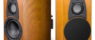
Dynamic drivers are the core and main component of any audio system. A modern standard mid-price speaker is equipped inside with at least two speakers - for low and high frequencies, respectively.
This is due to the fact that different speakers do not equally reproduce sound of different frequencies - the lower it is, the larger the diameter of the speaker should be. In systems with a subwoofer, the low-frequency emitter is placed in a separate housing so that it does not interfere with the sound of the others.
Today there are speaker systems on the market with two types of speakers. The first type uses a cone emitter, the so-called diffuser, the operating principle of which is based on the interaction of the magnetic field of an electric coil with the field of a permanent magnet. The output is powerful sound and rich bass.
The second type of speaker uses a flat membrane instead of a diffuser. Such emitters significantly lose in power, but have very compact dimensions. This makes them very effective in creating portable speaker systems.
They are also used in budget acoustics in conjunction with a subwoofer.
Creating a speaker system
Acoustic system
An acoustic system does not always indicate the presence of speakers. You can work on creating an acoustic system in a car like this:
- Make podiums from foam. For this:
- Make a template from cardboard. Attach it to the place where the podium should be.
- Using the template, cut out the base for the podium. For this purpose, ordinary plywood and reinforcement can be useful.
- The base consists of two rings. In this case, the diameter of the first ring must correspond to the diameter of the protective mesh. But the diameter of the second is the diameter of the column.
- The rings must be connected to each other using self-tapping screws.
- Cut six blocks to create a slope. Glue all the parts together.
- Pour polyurethane foam into the frame and leave it there until it dries.
- You will get a more interesting option if you use small pieces of different types of trees instead of plywood. In this case, you should select dry pieces of wood that do not have cracks. Everything on top should be thoroughly varnished to make the structure more reliable. For greater efficiency, everything can be secured using two slats.
- Mount the speakers into the sockets and install the podiums.
Thus, you can create acoustic speakers (see Repairing acoustic speakers: a detailed review) right at home and with your own hands. The price of such pleasure will not be high, since you will only need to spend money on purchasing the material. And in general, you can use any old speakers. The main thing is that they work and are in good condition. Of course, before starting this process, it is worth reviewing various photos and videos on this topic. The instructions will also be useful.
Plastic is cheap, but resonates
Plastic, which also includes composites, is often used in the production of budget speakers, those that are still Chinese. The plastic body is lightweight, significantly expands the possibilities of designers; thanks to casting, almost any shape can be realized.
Different types of plastics differ greatly in their acoustic properties.
Plastic is very popular when creating wearable speaker systems that operate via Bluetooth, such as JBL. At the same time, manufacturers managed to solve the problem of resonance.
Wireless speaker Philips SB500A
Just a few years ago, plastic was not very popular in the production of high-quality home acoustics.
But at the moment it is in demand for professional samples, where low weight and mobility of the device are important.
Acoustics design
Initially, select the number of columns, type, location. Obviously, producing more channels than a home theater has is an unwise tactical move. A cassette recorder will only need two speakers. At least six buildings will be released for the home theater (there will be more speakers). According to the needs, accessories are built into the furniture, the quality of low frequency reproduction is poor. Now the question of choosing speakers: in the publication by Naidenko and Karpov the nomenclature is given:
Three-way speaker system
- Low frequencies - CA21RE (H397) head with an 8-inch fit.
- Mid range - MP14RCY/P (H522) 5" head.
- High frequencies – head 27TDC (H1149) by 27 mm.
They presented the basic principles of designing acoustic systems, proposed an electrical circuit of a filter that cuts the flow into two parts (a list of three subranges is given above), and gave the name of purchased speakers that solve the problem of creating two stereo speakers. We avoid repetition; readers can take the trouble to look through the section and find specific titles.
The next question will be the filter. We believe that National Semiconductor will not be offended if we screenshot the drawing of the Ridico translation amplifier. The figure shows an active filter with a power supply of +15, -15 volts, 5 identical microcircuits (operational amplifiers), the cutoff frequency of the subbands is calculated by the formula shown in the image (duplicated in text):
f = 1/2P RC;
P – number Pi, known to schoolchildren (3.14); R, C – resistor and capacitance values. In the figure, R = 24 kOhm, C is silent.
Active filter powered by electric current
Taking into account the capabilities of the selected speakers, the reader will be able to select a parameter. The characteristics of the speaker's playback band are taken, the overlap junction between them is found, and the cutoff frequency is placed there. Thanks to the formula, we calculate the value of the capacitance. Avoid touching the resistance value, reason: it can (disputed fact) set the operating point of the amplifier, the transmission coefficient. On the frequency response given in the translation, which we omit, the limit is 1 kHz. Let's calculate the capacity of the specified case:
C = 1/2P Rf = 1/2 x 3.14 x 24000 x 1000 = 6.6 pF.
It’s not that big of a capacitance; it’s selected based on the maximum permissible voltage. In a circuit with sources of +15 and -15 V, it is unlikely that the nominal value exceeds the total level (30 volts), take a breakdown voltage (the reference book will help) of at least 50 volts. Do not try to install DC electrolytic capacitors; the circuit has a chance of blowing up. There is no point in looking for the original circuit diagram of the LM833 chip due to Sisyphean labor. Some readers will find a replacement chip that is different... we hope for your understanding.
Regarding the relatively small capacitance of the capacitors (retail and total), the description of the filter says: due to the low impedance of the heads without active components, the ratings would have to be increased. Naturally causing the appearance of distortions due to the presence of electrolytic capacitors and coils with a ferromagnetic core. Feel free to move the range division boundary, the total throughput remains the same.
Passive speaker filters
Passive filters will be assembled with your own hands by anyone trained in soldering in a school physics course. As a last resort, enlist the help of Gonorovsky; there is no better description of the intricacies of the passage of signals through radio-electronic lines that have nonlinear properties. The presented material interested the authors in low and high frequency filters. Those wishing to divide the signal into three parts should read works that reveal the basis of bandpass filters. The maximum permissible (or breakdown) voltage will be scanty, the nominal value will become significant. Matching the mentioned electrolytic capacitors are capacitances with a nominal value of tens of microfarads (three orders of magnitude higher than those used by an active filter).
Beginners are concerned about the issue of obtaining a voltage of +15, -15 V to power speaker systems. Wind a transformer (an example was given, PC program Trans50Hz), equip it with a full-wave rectifier (diode bridge), filter, enjoy. Finally, buy an active or passive filter. This thing is called a crossover, carefully select the speakers, correlate the ranges more accurately with the filter parameters.
What can you assemble a column from?
Gaming headsets discarded after so many years of service also became a good “donor”. The membrane part of the headphones simply cannot last forever - over time it fails, and the voice coils burn out. However, the headphone housing can be used as part of a homemade Bluetooth speaker.
In addition to consumables, you should purchase a set of regular bolts, washers and nuts. You also need to purchase glue that can dry in a couple of seconds; it is better to take the universal “Moment-1”.
Don't forget the materials for the lower part, buy several plugs. Almost all the goods from the list above can be safely purchased in the same supermarket with a construction or plumbing department.