Tube radios are not just a source of warm tube (literally) sound, but also excellent entertainment for enthusiasts and tech geeks, which allows you to effectively get rid of excess free time. Since many years have passed since the heyday of tube receivers, such devices can be modernized and made more high-tech. In this article I will tell you in detail how.
info
A year ago I already assembled a tube FM receiver with a counting detector, and it works quite well. You can read about this story in the article “Tube signal. We are assembling an FM radio receiver using lamps.”
I listened to the previous receiver throughout the coronavirus quarantine. However, the appetite comes with eating, and one day I got tired of turning two knobs to tune in to a station and following the marks, trying to catch the right frequency. I wanted convenience: this is the 21st century. Where is the frequency indication, where is the electronic tuning, where is all this? And then I just came across the Z5900 indicators!
Receiver assembly
Formulation of the problem
I have already written about frequency stabilization and indication, this is understandable. But there is another important point: receivers with low IF have an intractable problem - the mirror channel. And this problem manifests itself when it is necessary to receive a weak station, next to which there are two strong ones. As a result, we hear a signal from a strong station interfering with the mirror channel.
This can only be effectively combated by increasing the IF, for example to the standard value of 10.7 MHz, and with such an IF a fractional detector should be used. We'll settle it on that. As a result, a receiver with a digital local oscillator, indication and a classic (almost) tube circuit emerges.
Radio receiver device.
Space is literally filled with electromagnetic vibrations of varying lengths and strengths. The primary task of radio reception is to isolate the signal of a specific radio station from this mass. The receiver's input circuits contain a selector based on an oscillating circuit. Tuned to a certain frequency, it transmits well the signal of the radio station broadcasting at this frequency.
The next step is amplification of the received radio frequency signal and separation (detection) of the useful information component from it. Depending on the type of modulation of the received signal, various amplitude and frequency detector circuits are used. Moreover, most of the existing frequency detector circuits are designed for receivers with frequency conversion -
superheterodynes.
Design
Since a fairly high IF will be used, special attention should be paid to the design. Installation is carried out on an aluminum chassis measuring 260 × 70 × 50 mm. However, the body can be made larger, then there will be less fuss with tight installation. The case is stacked and consists of five aluminum panels 1.2 mm thick. The panels are connected to each other with aluminum corners using M3 screws. It’s better, of course, to bend a U-shaped chassis from a single sheet and screw the sides to it, it will be both stronger and prettier, but I didn’t have a sheet bender on hand.
My favorite plexiglass, unfortunately, is completely inapplicable for the analog part, since the lamps get hot, and the RF units require shielding. All installation should be carried out as rigidly as possible with a minimum length of connections. And the easiest way to fulfill these requirements is the Manhattan installation.
This type of installation is reminiscent of our breadboards and Zhutyaev’s technique. The parts are mounted on “spots” cut from foil getinax and glued to the chassis; everything is done quickly and works quite reliably. For the “spots” I used squares measuring 5 × 5 mm and 10 × 10 mm. It is convenient to cut such squares with a circular saw with a metal cutter; it can also be used to cut aluminum.
warning
Human bones are not much different in hardness from aluminum. Its circular saw cuts quite easily, so if you hesitate, you can shorten a couple of fingers. Be attentive and careful.
The case itself is used as a common wire, and for more convenient soldering, strips of copper foil are screwed to it. Capacitors in power circuits and coupling capacitors must be rated at least 200 V at a supply voltage of 180 V, and it is better to take an even larger margin.
Loop capacitors deserve special mention. The fact is that during operation the lamps heat up noticeably, and with them the receiver body and, accordingly, the capacitors in the circuits. Because of this, the frequency drifts away. To prevent this from happening, it is necessary to use capacitors with a low temperature coefficient of capacitance (TKE), these include capacitors with an NP0 dielectric. SMD capacitors can also be included in this category.
Contour coils
Loop coils in a tube superheterodyne are the most problematic issue. Especially now, when electronics has moved away from resonant circuits in favor of broadband ones. Nevertheless, on Ali you can find frames with trimmers at a very reasonable price, and I have already used them before in a HF receiver.
Therefore, in order not to reinvent the wheel, we will apply them here too. As for the screens, we will make them ourselves, fortunately it is not difficult. The coil is soldered onto a small scarf made of getinax, a small box is made from tin, and the scarf with the coil is soldered into it. Instead of tin, it is better to use copper, but tin works quite well, and most importantly, it is more affordable. A hole is made in the upper part of the screen to adjust the coil.
IF circuit and shield
If it is possible to take the frames of the IF circuits from a tube TV or receiver, then this is also a very good option. We will talk more about coils when discussing the amplifier and detector. The result should look something like what you can see in the pictures below.
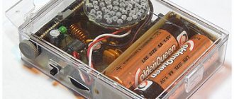
View from above
Side view
Bottom view
How does a radio transmitter work?
The basis of any radio transmitter is the master oscillator of the carrier frequency.
This generator circuit itself may well serve as a low-power transmitter (if there is an antenna). The electromagnetic oscillations of the frequency it generates do not themselves carry any useful information. To make it possible to transmit it, it is necessary to change the carrier frequency, modulating it with a useful signal.
Three types of modulation are used - amplitude, frequency and phase. With amplitude modulation, the amplitude of the carrier frequency changes in time with the amplitude of the information signal. Frequency modulation causes deviation (deviations) of the carrier frequency in time with the amplitude of the useful signal. With phase modulation, a similar thing happens with the phase of the carrier frequency oscillations.
The modulation process is carried out using various electronic circuits. For example, for frequency modulation it is necessary to influence such parameters of the master oscillator as the capacitance or inductance of its oscillatory circuit. If you apply low-frequency alternating voltage to the base-emitter junction of a transistor, this will cause its capacitance to change with the period of the applied frequency. Accordingly, frequency modulation of the master oscillator will occur.
If you assemble a similar circuit using the most common high-frequency transistors (for example, KT315), a dynamic type microphone, you can get a simple radio microphone. With coil L1, consisting of one turn of single-core wire with a diameter of 1-1.5 cm, it will cover the FM broadcast band.
The signal from such a device can be received at a distance of 50 to 150 meters, depending on the sensitivity of the receiver used. Fine adjustment is carried out by capacitor C5. Wiretapping devices - bugs - are assembled according to similar schemes. If a larger transmission range is required, the master oscillator signal must be further amplified using an output power amplifier and fed to the transmitting antenna.
The simplest transmitting antenna can be a piece of wire with a length of a quarter of the emitted wavelength. For amplitude modulation , it is necessary that the output power of the transmitter changes in accordance with the period of oscillation of the frequency of the useful signal. For this purpose, the effect of the amplified useful signal on the output power amplifier is used.
Scheme
We have already discussed the block diagram of a superheterodyne up and down and even found out why it is “super”. Here everything will be approximately the same: UHF, mixer, amplifier, detector, ULF. Below is a diagram of the VHF unit and the IF.
VHF unit and amplifier
VHF unit
Historically, in tube receivers the UHF mixer and local oscillator were made as a separate unit. This is due to the fact that the VHF part of the receiver needed careful shielding and required better installation, so it was more convenient for industry.
In addition, a number of specific circuit solutions were used there aimed at suppressing spurious radiation into the antenna. In our case, everything is simpler, since we use a synthesizer as a local oscillator.
The amplifier and converter are assembled on a 6N3P lamp; industrial VHF units are usually assembled on it. The use of triodes is due to their low noise level; instead of a 6N3P lamp, you can use a 6N23P or, at worst, another double triode. There are examples of using 6N1P and even 6N2P on the network.
The synthesizer output is 50 ohm, so it is convenient to feed its signal into the cathode circuit. To do this, the auto-bias cathode resistance is divided into two parts - 47 Ohms for connecting the synthesizer and 1 kOhm to provide the necessary bias.
The upper part of the divider is bypassed by a capacitor. The restructuring of the inverter circuit is carried out using a BB910 varicap. The circuit coil is frameless, wound with a wire with a diameter of 1.5 mm on a mandrel with a diameter of 12 mm and contains four turns. The IF output circuit serves to isolate the IF frequency and match the resistance with the ceramic filter. The contour coil contains twenty turns of wire with a diameter of 0.2 mm, the communication coil is wound on top of the contour coil and contains ten turns of the same wire.
In the converter, to receive the required signal, it is theoretically possible to use two local oscillator frequencies, above the signal by the IF value and below by the IF frequency. In this case, injection from below works much more efficiently, so we will use it. When receiving a powerful station, the output of the converter produces a signal of several millivolts.
The installation of the high-frequency part is as follows.
Installation of high frequency part
HRC
The amplifier is the main unit of the receiver. Most of the characteristics are determined by the HRC. And in the case of an FM receiver, conflicting requirements are placed on the amplifier. On the one hand, you need a bandwidth of about 300 kHz, and on the other hand, you need fairly steep frequency response slopes.
Classically, this problem was solved by distributed selection circuits, where in each stage there was a bandpass filter consisting of two loosely coupled circuits, and this is the best option. However, it turned out that creating such a filter using the frames I had was quite difficult. And the main problem here is the adjustment of the connection between the circuits, which greatly affects the frequency response. Actually, due to the problem with smooth control of communication, I abandoned this solution in favor of a scheme with concentrated selection, which is considered a more modern solution. More specifically, we will put a 10.7 MHz ceramic filter at the input of the amplifier. With this we will solve the problem of the steepness of the frequency response slopes and immediately obtain the required selectivity in the adjacent channel.
Unfortunately, the ceramic filter has a low input impedance, so it must be matched to the output impedance of the frequency converter. To do this, we use inductive coupling with the output circuit of the converter. There are no problems with matching the output impedance. Of course, a ceramic filter has an imperfect frequency response and a fairly large signal attenuation, but this is a small price to pay for simplicity.
A circuit with single circuits is not the best solution, but it is quite workable. Another problem is related to the amplifier's tendency to self-excite, especially with regard to the amplifier presented above. Because of this unpleasant feature, even when self-excitation was not observed, the frequency response of the amplifier changed depending on the warm-up and strength of the input signal (the gain increased, but the band narrowed). And this was all reflected in the sound.
This was treated by careful tuning in a warm state. Therefore, I abandoned the capacitively coupled circuit, and the final modification contains an inductively coupled amplifier. It produces slightly lower gain, but it is much more stable in operation.
Inductive coupling amplifier circuit
Actually, the fundamental problem with building a tube amplifier according to a concentrated selection scheme is that at frequencies above a couple of megahertz, non-resonant (aperiodic) tube amplifiers do not work. And that is why we did not have such a problem when building a receiver with a low IF. There we, without further ado, used aperiodic cascades.
This number won't work here, so you won't be able to get away from the contours. The easiest way is to assemble a resonant amplifier using pentodes; this will allow us not to encounter the peculiarities of triodes at high frequencies. A simplified formula for calculating the gain of a resonant cascade on a pentode looks like
K = SrQ
where S is the transconductance of the lamp (MA/V), r is the characteristic resistance of the circuit, Q is the quality factor of the circuit.
The actually measured gain is noticeably lower than this expression predicts. But for our estimates, we will limit ourselves to only this formula, from which it is obvious that it is better to take a lamp with a higher slope and a higher characteristic resistance. But with the quality factor it is more difficult, since as the quality factor increases, the bandwidth decreases, so a high quality factor will only hinder us. However, it can be reduced by bridging the circuit with a resistor, or by using mutually detuned circuits.
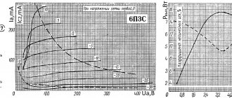
As a result, after a series of experiments, I came to an IF circuit coil containing 45 turns of 0.12 mm wire and a 10 pF circuit capacitor. The characteristic resistance of such a circuit is about 700 Ohms, and when it is shunted with a 15 K resistor, the quality factor is about 10. With such a circuit, from one stage on a 6AU6 (6Zh4P) lamp you can get a gain of about 20 and a bandwidth of about 1 MHz.
This is for a capacitively coupled amplifier. In an amplifier with inductive coupling, the coil is wound in two wires and its inductance turns out to be less for the same number of turns (here we are limited by the dimensions of the frame). Therefore, loop capacitors are already required at 33 R, and the characteristic resistance is about 400 Ohms. The gain of such a cascade is about 12.
The IFC uses Japanese 6AU6 lamps from NEC, but they can be easily replaced with our 6Zh4P. Similar results can be achieved with lamps 6Zh1P, 6Zh1B, 6K4P, 6Zh5P, a little worse with 6Zh2P, but you need to select the ratings of the parts in order to set the passport mode.
If you take a cooler lamp, such as 6Zh52P, you can increase the gain of the cascade to a hundred, but it came into my hands too late, and it eats electricity like three 6AU6s. I didn’t bother with the AGC either, especially considering the modest gain of the amplifier, but the limiter would be very useful.
Limiter and Fractional Detector
A fractional detector is quite a tricky thing, and it’s impossible to simply explain its operation with fingers. But this very principle is based on changing the phase of oscillations in two connected circuits. So, when tuning to resonance in the second circuit, the phase is shifted by 90°, and when detuned, the phase shift changes up or down depending on the frequency.
Thus, by adding the original (in-phase) signal with a signal shifted in phase by an angle proportional to the change in the frequency of the original signal, we move from frequency modulation to amplitude modulation. And the rest of the scheme is a matter of specific implementation. You can read more about this here or here.
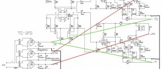
The frequency discriminator and fractional detector operate on this principle. The fractional detector has some advantage in that it is less sensitive to spurious amplitude modulation. This is exactly what I used in the receiver. The figure below shows a diagram of a limiter and a fractional detector.
Fractional detector and limiter
Generally speaking, a limiter for a fractional detector is not necessary, but it works better. Structurally, the detector is made in the form of a separate block and is entirely placed in a screen, which has holes for adjusting the contours. Most of the parts are SMD-made, which helped reduce the dimensions.
The detector is almost assembled
Detector board
Screen
The coils are made on the previously mentioned L4 cores and contain 20 turns of 0.2 mm enameled wire. Coil L5 is wound on top of L4 and contains five turns of the same wire. Coil L6 is wound on a separate frame with a double wire and contains 12 + 12 turns. The frames themselves are placed at a distance of 10 mm from each other.
1N34 diodes can be replaced with more authentic D2 or D9. Oddly enough, despite my expectations, there were no problems in setting up the fractional detector; the main thing was to get into the desired frequency range, which was solved by selecting capacitors C6 and C7.
As for the limiter, it comes from a conventional amplifier stage with a reduced voltage on the accelerating electrode and a low anode current, which limits the amplitude in the anode circuit. In addition, the cascade operates without bias and somewhat limits the amplitude of the input signal due to the grid current.
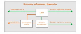
Ultrasound and power supply
The audio amplifier is made according to a completely typical single-ended circuit using a 6F5P lamp and completely replicates the ultrasonic frequency of the previously mentioned receiver with a low IF. There is probably nothing more to discuss here; there is even more information on the Internet on the topic of tube single-ended amplifiers than is necessary. The only thing worth mentioning is grounding the filament circuit through resistors: this solution allows you to suppress a background of 50 Hz.
UZCH and BP
The power supply is made on a TAN-3 transformer, the circuit is completely typical.
Various radio wave bands.
Radio waves are divided into different radio bands, depending on their length.
What is radio wavelength? Radio waves travel at the speed of light (which itself is one of the ranges of electromagnetic vibrations). In a second, they spread over a distance of about 300,000 kilometers. By dividing this distance by the frequency of electromagnetic oscillations, you can find out their wavelength. For example, vibrations with a frequency from 3 to 30 kHz. generate ultra-long range radio waves. Accordingly, the length of ultra-long radio waves ranges from 10 to 100 kilometers. Transmission of information over long distances in this range is possible using very large transmitting antenna devices (more than a kilometer) and very powerful transmitters. Ultralong waves are used for long-distance underwater communications.
Oscillations with a frequency of 30 to 300 kHz cause long-wave radio waves. Their length is from 1 to 10 kilometers. They are able to bend around the earth's surface due to the phenomenon of diffraction. Diffraction of radio waves is their ability to bend, to one degree or another, obstacles lying in the path of propagation - the convexity of the globe, mountains, buildings, etc. etc.
Diffraction occurs as a result of the excitation of high-frequency oscillations on the surface of obstacles by a radio wave. These vibrations in turn cause secondary radiation of radio waves that penetrate into areas of space obscured by the transmitting antenna of the radio transmitter. In this case, part of the energy of radio waves is inevitably lost - to heating the surface.
Longwave transmitting antennas are quite large, as is the transmitter power.
The main advantage of long waves is the possibility of very stable communication over a long distance - without a repeater.
Frequencies from 0.3 to 3 MHz belong to the medium wave range, from 3 to 30 MHz to the short wave range. Waves in these ranges are capable of being reflected from various layers of the ionosphere, which facilitates ultra-long-range communication, with a relatively low transmitter power and small size of the transmitting antenna.
The propagation of radio waves over long distances due to spatial waves is explained by reflection in the ionosphere. Along with reflection, partial absorption occurs, which increases with increasing wavelength.
Reflection and absorption in the ionosphere are also related to the electron concentration, which is not a constant value. Its changes are cyclical - daily, seasonal and associated with the 11-year solar cycle, but sudden changes often occur - due to solar flares and falling meteor showers.
Frequencies from 30 MHz to 3 GHz are ultrashort (meter and decimeter) radio waves. Radio waves in this range are well absorbed by the earth's surface and pass through the ionosphere - stable communication is possible up to the horizon. The advantage here is high-quality communication, with extremely low transmitter power - and, accordingly, the possibility of miniaturizing its size.
The ultra-high frequency range 3 - 30 GHz (centimeter) is used for space communications. Electromagnetic vibrations of this frequency are very close to light in their properties. They can be easily focused using spherical reflectors for transmission over very long distances.
Direct conversion receiver.
There is, however, another type of receiver that can receive signals in all ranges and any modulation - without a detector.
We are talking about direct conversion receivers - heterodyne or synchrodyne, as they are also called. The synchrodyne circuit contains a mixer, a local oscillator and an audio amplifier. Reception is carried out as follows - the useful signal passes from the antenna to the mixer, where high-frequency oscillations from the local oscillator are constantly supplied (its frequency can be changed).
As soon as the frequencies of the useful signal and the local oscillator coincide, beats with the modulation frequency appear at the output of the mixer, i.e., a low-frequency informative component. The resulting signal can be reproduced after sufficient amplification. Despite its simplicity and efficiency, the direct conversion scheme has received only limited distribution - due to the insufficiently high quality of music and speech transmission.
To the main page To the beginning
The use of any materials from this page is permitted provided there is a link to the “Electrical is Easy” website.
Detector receiver.
A detector receiver is the simplest device that allows you to receive broadcast radio stations using amplitude modulation.
A classic detector receiver designed for reception in the long and medium wave range consists of an oscillating circuit, an amplitude detector assembled on a single diode, and high-impedance headphones (earphones, to put it simply). A drawing illustrating the operating principle of an amplitude detector. In the figure, the diode “cuts off” the negative component of the radio signal. Then, the filter capacitance extracts the envelope of the rectified high-frequency signal - a low-frequency signal is obtained. This is what the circuit of a real detector receiver might look like.
As an oscillating circuit, you can use a variable capacitor (C1) from any faulty industrial receiver and a magnetic antenna from the same. Headphones - vintage TON-2 headphones.
Such a receiver does not have an amplifier, so the radio signal at its input must be strong enough. Hence, it is necessary to connect an extended (at least 10 meters) external antenna and grounding.
Superheterodyne.
Superheterodyne, a frequency conversion receiver, is the most common circuit. It contains a low-power intermediate frequency oscillator - a local oscillator.
The local oscillator generation frequency changes simultaneously with the change in the input frequency setting. For this, a two-section variable capacitor is used - one section is used in the input oscillatory circuit, the second in the local oscillator circuit.
Moreover, the local oscillator is tuned in such a way that the difference between its natural frequency and the frequency of the radio signal remains approximately unchanged throughout the entire tunable range. This is the intermediate frequency that is released in the mixer - a cascade where both frequencies meet. Moreover, the intermediate frequency obtained in this way turns out to be modulated by the useful signal.
Next, the intermediate frequency is amplified by intermediate frequency amplifier stages. Such stages have an increased gain only at this frequency, which eliminates self-excitation of the amplifier. After amplification of the intermediate frequency, detection and final amplification of the useful signal occurs. The superheterodyne provides high selectivity and sufficient sensitivity to operate in all broadcast bands.
In addition, it becomes possible to receive and detect frequency-modulated signals at VHF frequencies, which significantly improves the quality of sound reproduction. The most common frequency detector circuit is balanced, containing two circuits tuned to the carrier frequency with some deviation - slightly mismatched. The frequency of the first of them is adjusted slightly higher, and the second – slightly lower than the intermediate frequency.
The modulated intermediate frequency, deviating from its average value, induces oscillations (maybe audio) of the useful signal, released on resistors R1 and R2.