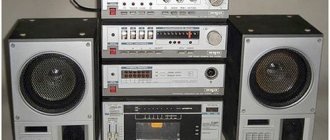
Many radio amateurs are not satisfied with the sound of industrial sound systems, so the problem of how to make a speaker amplifier with your own hands is an interesting one. There are many schemes that are suitable for repetition by beginning radio amateurs. They are assembled using accessible and inexpensive parts, are easy to manufacture and do not require complex setup. You can first make a sound amplifier of the simplest type , and then move on to more complex designs.
Powerful DIY sound amplifier
A radio amateur planning to make a low frequency (LF) system must resolve a number of the following issues:
- Element base
- Electrical parameters
- Scheme selection
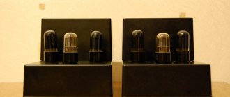
Modern sound systems are assembled using bipolar or field-effect transistors and integrated circuits. Such designs do not require high voltage in the power supply circuits, are quite compact and provide a good range of reproducible frequencies and a low percentage of distortion. High-end audio equipment is assembled using vacuum tubes, which have not been used in mass-produced technology for a long time. Electrical parameters depend on the purpose for which the ULF will be used. The design, intended for connection to a tablet or computer, does not imply high quality sound reproduction.
For a specialist, it will be easy to assemble an audio amplifier with your own hands , providing fairly high parameters. In this design, you can use powerful transistors or microcircuits. The block can be designed to work with devices that produce a powerful output signal. Then a preliminary cascade is not required and it is enough to assemble only the tip. If the device is intended to work with a microphone, turntable or electric guitar, then you will have to assemble a complete path with a preliminary stage and tone controls. The easiest way to assemble a final power amplifier with your own hands This design is assembled on a simple printed circuit board, does not require adjustments or adjustments, and if assembled correctly it starts working immediately.
The design provides an output power of up to 20 watts per channel, operates from 10 to 18 V, so can be used in a car. This power is provided using the TDA1557 chip. The TDA8560Q can deliver up to 30 watts per channel. For more stable operation of the design when reproducing low frequencies, it is recommended to use 5 2200 µF capacitors connected in parallel in the power filter. The chip body gets very hot, so it needs to be installed on a radiator. To assemble a sound amplifier for speakers with your own hands, you will need a tester and a soldering iron. An oscilloscope and generator are not used for simple circuits.
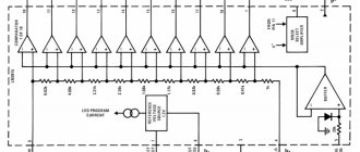
ULF TDA8196 12 dB
A simple power amplifier circuit using TDA8196. Scheme for a beginner radio amateur. Doesn't require many parts and is easy to assemble. Miniature bridge low frequency power amplifier with electronic volume control.
There is protection for the output stage against short circuits and thermal protection against overloads. And of course, protection against static. The amplifier can be adjusted either with a potentiometer or with a simple electronic volume control.
Specifications of TDA8196
| Supply voltage Upit | 10.8 - 13.2 V |
| Current consumption Ipotr | 12 mA |
| Reference voltage Uref | 6.6 V |
| Audio input impedance | 10 - 13 kOhm |
| Audio input impedance | 0.2 - 1 kOhm |
| Harmonic coefficient Kr | 0,4 — 1 % |
| Output noise voltage | 40 µV |
Chip Limits
| Supply voltage Upit | 16 V |
| Working temperature Trab | -55…+125 °C |
| Storage temperature | 0…+70 °C |
How to assemble a sound amplifier
It makes no sense for beginning radio amateurs to undertake the task of repeating complex transistor circuits with high parameters. To adjust such structures, complex measuring equipment will be required. The easiest option for beginners would be to repeat circuits made using integrated components. To begin with, you can assemble a simple low-power audio amplifier .
The LM386 chip operates over a wide supply voltage range and provides power up to 1.2 watts into an 8 ohm load. The signal distortion coefficient does not exceed 0.2%. A variable resistor of 4.7 kOhm allows you to change the gain from 20 to 200. A homemade device can be assembled on a breadboard or mounted.
For laptop
The sound wave amplifier must take into account the power of external speakers up to 2 watts and winding resistance up to 4 ohms.
Assembly components:
- 9 volt power supply
- printed circuit board
- chip TDA 7231
- frame
- non-polar capacitor 0.1 µF - 2 pcs.
- polar capacitor 100 µF
- polar capacitor 220 µF
- polar capacitor 470 µF
- constant resistor 10 Kom m 4.7 Ohm
- two-position switch
- input socket
DIY stereo sound amplifier
to assemble a high-quality stereo sound amplifier for speakers with your own hands , since such circuits require careful adjustment and debugging. There are circuits that provide high sound quality without complex settings. The proposed design is an ultra-linear circuit operating in class “A”. This means that the output signal is virtually undistorted and follows the shape of the input signal. Transistors KT803, KT805 or KT819 can be used in the output stage. From the output of the cascade you can get up to 15 watts of power, and the distortion is minimal and corresponds to the parameters of the highest class equipment.
A circuit operating in this mode consumes a lot of current, and the output transistors heat up in the absence of a signal, so they are installed on radiators. To make your own audio amplifier for stereo speakers, two circuits are assembled - for the right and left channels. If the design will be used for a car radio, then this circuit is sufficient. In other cases, a preliminary stage with gain, tone and stereo balance controls will be required. It is best to solder the audio amplifier on a printed circuit board. The output transistors are mounted on radiators. For reliable cooling, you can use a cooler from a computer power supply. Capacitor C2 must be film.
increase the power of a sound amplifier with your own hands by increasing the supply voltage by 10-15%. First you need to find out the critical voltage values for transistors. In some cases, increasing the input signal will help. This will drive the output stage more efficiently.
The question of how to make a powerful sound amplifier with your own hands often arises among radio amateurs with little experience. It makes no sense to take on a transistor circuit. It is difficult, time consuming and there is no guarantee that the design will work. It is best to use special microcircuits. An integrated ULF can output hundreds of watts, and the circuit does not need adjustment.
TDA8567q 4x25 W
Hi-Fi class bridge amplifier for four channels.
There is protection against short circuit of the output stage and thermal protection with a reduction in output power when overheated. The microcircuit also has protection against voltage fluctuations and a shutdown mode. This microcircuit also has an on/off mode for the input signal (Mute mode), and protection against “clicking” when voltage is applied to the circuit.
Chip characteristics
| Parameter | Meaning |
| Upit | 6-18 V |
| Iout | 7.5 A |
| Irest | 230 mA |
| Pout | 4x25 W |
| Rin | 30 kOhm |
| Gain | 26 dB |
| Frequency band | 20-20000 Hz |
| Harmonic distortion | 0,05 % |
| Rload | 4 ohm |
Pin assignment
| Pin number | Purpose |
| 1 | Supply voltage |
| 2 | Exit 1+ |
| 3 | General |
| 4 | Output 1- |
| 5 | Output 2- |
| 6 | General |
| 7 | Exit 2+ |
| 8 | Supply voltage |
| 9 | Diagnostics |
| 10 | Input 1 |
| 11 | Entrance 2 |
| 12 | General signal |
| 13 | Entrance 3 |
| 14 | Entrance 4 |
| 15 | Mode selection |
| 16 | Supply voltage |
| 17 | Exit 3+ |
| 18 | General |
| 19 | Output 3- |
| 20 | Output 4- |
| 21 | General |
| 22 | Exit 4+ |
| 23 | Supply voltage |
DIY speaker amplifier for dummies
Typically, designs with high output power are used for subwoofers, but if there are powerful speaker systems, then such a design can be used for sounding large rooms. Such ULFs require a properly selected power source, and for correct operation you need to consider cooling the output stages or the housing of a powerful microcircuit.
A simple high-power low-frequency block circuit can be assembled using several types of integrated circuits, but the pin numbering does not change. Output power (W) corresponds to the following types of chips:
- PA01 – 50
- OPA12 – 60
- TSC1468 – 120
- PA04 – 400
- PA03 – 1000
Homemade sound amplifiers , made with your own hands using serviceable elements and careful installation, can provide good parameters. The structure is powered from a bipolar power source with a voltage of 15 to 45 volts. In addition to PA01, the maximum voltage for which should not exceed 28 volts. Broadband speakers are used as a load, since the amplitude-frequency response is quite linear in the range of 10 Hz-40 kHz. The coefficient of nonlinear distortion at a frequency of 1 kHz and an output power of 50 watts does not exceed 0.005%. Despite the fact that the microcircuits are quite expensive, you can use them to assemble a good sound amplifier .
Technical characteristics of ultrasonic sounder
In real measurements, the amplifier achieved the following parameters:
- output power 2 x 53 W
- frequency response 5 Hz – 330 kHz
- internal resistance 0.15 Ohm.
Naturally, all this can be simplified by removing the digital control and remote control unit, eliminating a separate headphone amplifier, removing the signal through a resistor divider from the main one, simplifying the power supply, indication, and so on, but the goal was to do everything to the highest standard, so TDA-amps are here not the place))
DIY mini sound amplifier for speakers
Such a design should have a small number of accessible parts, be easy to assemble and not require adjustment. Common and inexpensive microcircuits are best suited for this purpose. They are used in commercial equipment, but they can be used for homemade projects. The design will be able to provide an output power sufficient to sound a medium-sized room. How to make the simplest sound amplifier with your own hands will be clear after reading this article.
to assemble a simple mini sound amplifier with your own hands, using a ready-made module with a RAM8403 chip. This design will not require any discrete elements, since they are provided in the circuit. All you need to do is connect the speakers, power and apply the input signal. The speaker impedance should be 6-8 ohms. Output power reaches 2 watts per channel.
ULF TDA8198 12 dB
The TDA8198 chip is manufactured in a DIP14 package and is used in high-end equipment.
The dynamic signal level is 90 dB.
There is protection of the output stage from short-circuit and static.
Chip characteristics
| Supply voltage Upit | 10.8 - 13.2 V |
| Current consumption Ipotr | 24 - 32 mA |
| Reference voltage Uref | 6.9 V |
| Output noise voltage Uout noise | 300 µV |
| Harmonic coefficient Kr | 0,3 — 1 % |
| Audio input impedance Rin | 22 kOhm |
| Audio output impedance Rout | 10 - 300 Ohm |
Chip Limits
| Supply voltage Upit | 16 V |
| Working temperature Trab | -55…+125 °C |
| Storage temperature | 0…+70 °C |
Complete DIY sound amplifier
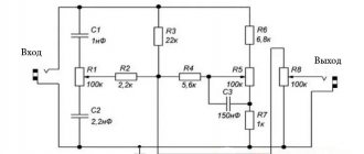
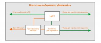
A complete audio amplifier consists of a pre-stage and a final stage, which can be implemented using transistors or integrated circuits. To assemble an audio amplifier with your own hands, you need to have experience and the necessary technical equipment, since it is impossible to set up such a design without measuring instruments. Block diagram of a full amplifier.
Adjustment of the device can only be performed by an experienced radio amateur. The figure shows the diagram of one input channel. The stereophonic path includes two such circuits. This stage with active tone controls and volume control with compensation can be connected to any final stage. The pre-stage is assembled using a dual high-speed operational amplifier LM833 and a TL071. Instead, you can use op-amp 544 series.
Microcircuits
The TDA series microcircuit and a similar one can be purchased in stores or you can use a microcircuit from an unnecessary TV.
Using car amplifier chips with a 12-volt power supply, it is very easy to achieve high-quality sound without the use of special skills and with a minimum of parts.
Simple DIY audio amplifier
The simplest do-it-yourself sound amplifier is assembled using a TDA7231 chip . The presented circuit provides an output power of up to 1.5 watts into a four-ohm load. The microcircuit has a large acceptable power supply range, so ULF can be used in battery designs. The device's quiescent current does not exceed 8 mA. The current consumption at maximum power reaches 1.5 A. Any dynamic head with a resistance of 4 Ohms can be connected to the device. This design is not suitable for high-quality music playback due to the high percentage of distortion, which reaches 8% at maximum volume. The device can be used in self-powered electronic toys or security alarm systems.
A simple audio amplifier for home is easily assembled on a 4069 chip, which contains 6 inverters. The system is suitable for connecting headphones when listening to music files from a computer, phone or tablet. A simple circuit provides satisfactory parameters.
By changing the resistance of resistors R2 and R3, you can change the gain of the device. For this ULF it is not necessary to make a printed circuit board. A standard breadboard with plated holes will do.
There are many simple designs that can be repeated by radio amateurs with little experience. To manufacture such devices, you only need a tester to check the main circuits. After you gain experience in the process of manufacturing and setting up simple circuits, you can move on to more complex systems.
Car amplifier
What is needed to make a sound amplifier in this case:
- cooler or radiator for cooling;
- filter against interference created by electromagnetic radiation of the machine;
- TDA8569Q chip.
You can purchase this microcircuit at any radio store at an affordable price. It is recommended to make the filter yourself - this is an additional saving.
According to the diagram that is attached to the microcircuit, a board should be created and etched with ferric chloride. The microcircuit is soldered in a thick layer in the area of the power paths.
The filter is made of a ferrite ring D=20 mm and a cable with a cross-section of 1.5 mm and 5 turns. This add-on protects against any type of interference.
ULF circuit on TDA7236
The microcircuit is in a minidip (4+4) package.
Chip characteristics
| Supply voltage Upit | 1.8 - 24 V |
| Current consumption with idle mode Ipotr | 5 mA |
| Output power Pout | 1.7 W |
| Harmonic coefficient Kr | 0,3 — 1 % |
| Gain (closed loop) | 38 dB |
| Input resistance Rin | 100 kOhm |
Limit parameters
| Supply voltage Upit | 28 V |
| Output current Iout | 1 A |
| Power dissipation Pdis | 500 mW (SZIP package), 800 mW (SSOP package) |
| Temperature Tb | 40…+150 °C |
Bridge to TDA7240
A miniature but quite powerful low-frequency power amplifier, made using a bridge circuit.
The amplifier has:
- Protection of the output stage from short circuit;
- Thermal protection in case of overload;
- Reliable protection against surges up to 28 V.
Chip characteristics
| Upit | 6 - 18 V |
| Iout max | 4.5 A |
| Irest | 150 mA |
| Pout | 20 W |
| Rin | 50 kOhm |
| Gain | 40 dB |
| Frequency band | 30 - 25 kHz |
| Harmonic distortion | 0,5 % |
| Rload | 4 ohm |
Pin assignment
| Pin number | Purpose |
| 1 | Distortion Compensation Circuit Output |
| 2 | Output of correction scheme |
| 3 | Entrance |
| 4 | General |
| 5 | Output 1 |
| 6 | Supply voltage |
| 7 | Exit 2 |