Impedance
Impedance If your amplifier has separate outputs (or a switch) for acoustics with a nominal impedance of 4 or 8 Ohms, then you can skip this point. Although in this case you should not focus on 6-ohm acoustics if such a switch position is not provided. But most modern amplifiers do not have such a switch - the manufacturer makes their life easier, simultaneously reducing the factory price of the product. And when working with acoustics with the “wrong” impedance, the output power of the amplifier will be reduced. Your task is to find out what load impedance the amplifier is designed for and choose speakers with the same nominal impedance. The task is complicated by the fact that many acoustics manufacturers do not indicate the nominal value, limiting themselves to an inscription like “4 - 8 Ohms”. You can use a tester: with a nominal value of 4 Ohms, it should show from 3 to 4 Ohms at the contact terminals, with other nominal values - proportional values. To tell the truth, it is not convenient to take measurements in a store; then you can search the Internet for test results, which show a graph of the impedance characteristics for a given acoustic system. The lowest point on the bass will approximately correspond to the tester's readings.
Some offal or technopron
Before starting the renovation, let's enjoy the rich inner world. Before that, let's read the warning:
On top are the power supply, radio, and record player.
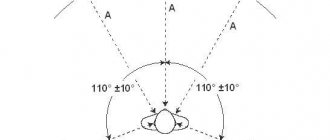
Below are 4 speakers and a VHF antenna.
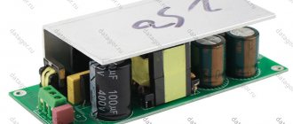
Power supply transformer with different input voltages
Space technology - radio receiver
And variable capacitor
Sensitivity
There are no extra watts for a “lamp”, and therefore you need to choose acoustics with good sensitivity. For this reason, shelf models (in the vast majority) can be excluded from consideration. However, it is not so likely that you have somewhere to put a tube amplifier, but there is no place for floor-standing speakers. A certain difficulty here is that manufacturers most often indicate sensitivity normalized to a voltage of 2.83 V (denoted SPL). Therefore, it is necessary to introduce a correction if the nominal impedance of the acoustics differs from 8 Ohms. Taking this correction into account, 90 dB for a 4 Ohm speaker, 88.5 dB for a 6 Ohm speaker, and 87 Ohm for an 8 Ohm speaker will mean the same sensitivity. If you get at least 89 dB/W, that’s not bad, but 91-92 dB/W is even better.
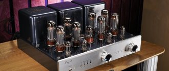
Layout, installation, assembly of a tube SE amplifier.
Sergey Nikitin
Second part (continued).
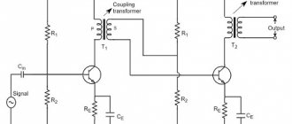
Well, let’s assume that our output transformers are wound, soaked, dried and ready for “use.”
Now we need to decide on the power transformer; So, let’s take as a basis the anode current with an eye to the KT88 lamp, which reaches 0.1 A, we have two of them, the anode voltage is 380 V, we get 380 Vx0.1Ax2 = 76 W. Driver lamps (drivers) have an anode current of up to 10 mA for two channels, powered from the anode 380 V, we get 3.8 W. The output lamp heat is 1.7A, on boost 0.6A, indicator 0.3A, multiply by 2, we get 5.2A, multiply by 6.6V, we get 34.32W. Now we decide what kind of rectifier we will have, diodes or kenotron. The rectifier with diodes is much simpler, but you need to delay the supply of the anode voltage, and the diodes will interfere with the output transformers.
The rectifier on a kenotron is more complicated; you need to wind it on a transformer. the filament winding is 5 Volts, and the anode voltage is almost equal to the AC output from the transformer, and without load until the lamps are completely warmed up, it briefly rises by 1.41 times. The anode winding here should be with a middle point, which also complicates the winding of the power transformer, but there is no need to delay the switching on of the high voltage and there is no interference in the audio path, the sound is much more pleasant, there are no semiconductor diodes, which makes the device a real antique, and the rectifier needs to be changed ( kenotron) is much simpler.
That’s it, we’ve decided, we count it under the kenotron.
5 Volts multiplied by a filament current of 3 A (5Ts3S) we get 15 W. Now we add everything up, 76 W + 34 W + 3.8 W + 15 W = 128.8 W, this is how much our amplifier will consume in the form of heat, for reserve and convenience we take the standard OSM-0.16 kVA and try it. Let’s try the following: some OSM transformers have such a huge magnetic field (they are slightly unwired and were designed for high induction) that they interfere with the output transformers, which cannot be removed by anything. First, we check the no-load current of the OSM, and if it is within 0.1 A, then it is normal, it will be quite possible to use it. You can do it another way; Connect the transformer to the network, load it with anything acceptable, place an audio transformer next to it, to the output winding of which your speaker system is connected, and by moving it in different planes, try to hear the hum in the speakers. If it doesn’t hum, then it’s great, and if it hums, then it will continue to hum after you rewind and reassemble it.
Now we start winding the power one, but first we need to disassemble it, and before that apply exactly 220 Volts to its mains winding, and measure the exact output voltage on any output winding, remember the value and winding. When you wind the secondary, be sure to count how many turns on this winding, divide by the measured voltage, and get the number of turns per 1 volt. I got 2.24 turns per 1 Volt. We wind it up to the network winding, check the quality of the insulation, it would be advisable to lay five to seven layers of paper there, and different types of paper, for example, regular printing paper and notebook paper, or special paper.
Since we are planning a kenotron, this is a full-wave rectifier, which means the anode winding will consist of two symmetrical halves, but for greater versatility, we will make it with taps. Using the reference book from the table, we look at what wire we need to get a current of about 0.25A, the current density here can be 4-5 A mm.sq., since the load on this winding is pulsed (dynamic), it turns out that a wire with a diameter of 0.25 mm for This will do. Then we look at what diameter is needed for the filament windings, their load is constant (static), so here we take a current density of 2-2.5 A mm.sq. (so that the transformer does not get too hot), it turns out 1.25 -1.4 mm for the kenotron, 2.0 mm for the filament of the remaining lamps. We calculate all the turns, rows, layers, insulation and check that everything fits.
Knowing that for 1 Volt we need 2.24 turns, we calculate: 320V x 2.24 = 716 turns, plus an additional 30 Volt x 2.24 = 67 turns.
ATTENTION: we wind the winding in the following sequence. 67 + 716 + 67 + 716, naturally we make bends. Three layers of insulation. Then we wind an additional 50 Volt winding with a 0.25 mm wire, just in case we suddenly want to use external bias of the output lamps. There are four layers of insulation, because the next winding is made of thick wires and can damage the insulation. We wind the filament of the lamps, it occupies part of the row, again there are two or three layers of insulation and in the free space we wind the filament of the kenotron. It is advisable to separate this winding from the filament winding of the amplifier lamps, since it will be at anode voltage potential. We seal, assemble, check the transformer to make sure it doesn’t hum, and apply varnish to the same quality as sound transformers.
Everything, dried, checked. We connect the power transformer to the network, and connect a powerful car lamp or something similar to the filament winding. We connect the oscilloscope to the anode winding of the sound transformer, set the most sensitive voltage measurement limit, bring it to the power transformer and position them among themselves so that the coils do not coincide in any plane, look for a position where there is a minimum distance between the power and sound transformers, according to the oscilloscope we have a minimum of interference. This usually happens when the centers of the transformers are in the same plane; this is the most optimal placement method, where electromagnetic alignment is obtained. It will be approximately the same as in the picture.
After this, you can already estimate the dimensions of the future amplifier. And don’t forget about the heat shields in front of the transformers; the lamps get very hot. My heat shields are made from a mirror from an old photo glosser. You can do it without screens, just move the lamps further away from the transformers.
The panel (chassis) on which the lamp panels and everything else are mounted should preferably be made of metal; for me it is made from the cover of an electrical panel, followed by painting in the desired color.
We attach the lamp panels on top of our chassis (electrical panel cover).
Now how to arrange them. Here you can do as you like, but it would be more correct for the signal circuits to be as short as possible, i.e. from the anode of one lamp to the grid of another - as short as possible. But sometimes such placement does not turn out so beautifully from the outside when the anodes of the lamps are turned randomly.
This is how everything is inside at first. The body was made of real wood (door frame, or floor plinth), and there were difficulties with 45 degree cuts at home.
All electrical power wires must be twisted (twisted) in pairs, to reduce interference, signal wires are twisted in the same way, signal wires cross electrical wires at right angles and at the greatest possible distance. Therefore, I run all the signal wires at the base of the chassis itself, and the filament, power and anode wires closer to the bottom cover. I do the installation hinged, it is very convenient for selection and various experiments.
What else is worth paying attention to in detail?
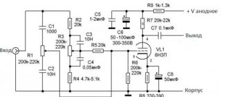
Everything where sound flows must have minimal inductance. In the first grid (and in the output lamp it is necessary) it is advisable to install an anti-ringing resistor, which will prevent your cascade from switching to high-frequency generation mode. Resistors are suitable for MLT, OMLT and others with the appropriate power.
Never use wirewound resistors in audio circuits. Here I have all 2W resistors, it’s convenient to install, and it’s difficult to break accidentally. In the filament circuit of the kenotron, due to the fact that the filament voltage turned out to be more than 5V, it was necessary to install 5W ballast resistors, this gives an additional delay in the supply of the anode voltage. Due to the fact that in the first seconds the anode voltage is too high and is about 430 Volts, all smoothing capacitors must be at a voltage of at least 450V. All electrolytes are bypassed with conventional capacitors, in the region of 0.47-1.0 μF for a voltage of at least 450V. It is advisable to use good capacitors; there are various articles about this on the Internet. K73-9 and K73-17 are an extreme case, K73-15, K73-11 are not bad, K78 is not bad, but it is better to combine CBG and K40 with them.
I really didn’t like the imported analogues of our K73-17 capacitors, like these in yellow cases.
Between stages, be sure to use only good capacitors, otherwise all the work done will not be interesting. All capacitors sound differently, some ring, others fall off.
I liked the capacitors of this kind, 0.1 µF 200V, which sounded very good, they sound great.
There are a lot of interesting old Soviet capacitors, you can experiment.
PTFE capacitors sound good. You might also like the paper ones, they will have a kind of retro sound, the high frequencies will be subdued. These are the capacitors I also used.
And I even used these capacitors. I pierced a hole in the side, poured capacitor oil from high-voltage capacitors inside, carefully sealed it, let it soak for two weeks, and then listened. The highs are a little lacking, but the sound is interesting and lively.
I don’t recommend installing such capacitors (BTM-1, MBM) as interstage capacitors - they are useless, although, as they say, all bananas taste and color differently.
I bought some pretty good capacitors from Audiomania, not expensive ones, like these. I repeat once again, the sound depends very much on capacitors (especially interstage ones).
Ready-made chokes from an old tube TV were used as filter chokes. You can make them yourself by winding them with wire of about 0.3-0.35 mm, until the frame of any transformer convenient for this is filled with a small (about 10 W) power. But during assembly, be sure to make a magnetic gap in the magnetic core of 0.1-0.2 mm.
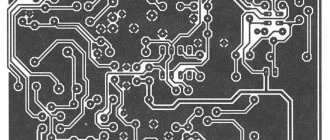
The common bus is made of 2.5mm tinned copper wire, connected to the amplifier chassis in the center and routed in both directions. It should not touch the body anywhere else, only at one point. All common conductors are soldered to this bus at the shortest distance, there should be no loops, common wires must be made of copper wire with a cross-section of at least 1 mm2, to reduce inductance and so as not to make your amplifier an ordinary radio transmitter.
Be sure to insulate the anode circuits with double insulation; if they touch something somewhere, be sure to lay a PVC pipe (cambric), otherwise it may burn out. The filament circuits through R19-R22 are under a positive voltage of 60-70 Volts, this reduces the background of alternating current, they can be mounted on the body, but positive bias is more effective. This chain also contributes to the discharge of the anode supply storage capacitors after the amplifier is disconnected from the network.
To connect the input connectors to the volume control and from the volume control to the input lamps, a twisted pair of FTP multi-core wire is used, two twisted pairs (to increase the wire cross-section) are twisted together, this is one wire (signal), a second wire (common) is also made, these wires are twisted together and connected to the corresponding sections of the circuit. For some reason, I like twisted wires more than coaxial or shielded ones. You can use MGTF or similar multi-core and even electrical wires instead of twisted pairs, if the copper there has not become oxides. For signal circuits, use copper wire that is free of oxides, including for speakers. Do not buy an audio cable in regular stores, it is made of aluminum, with a copper coating, which oxidizes over time, and you will puzzle for a long time why it doesn’t sound to you - check it yourself. A good copper audio cable starts at 10 units per meter.
Well, now you have assembled everything, soldered it, everything is clearly visible what goes where. We checked again. It is advisable to do the first switching on through an LATR, or through an incandescent lamp with a power equal to the power of the power transformer. LATR-th gradually raise the voltage, wait, check the values of the anode voltages, filament voltages, raise further.
ATTENTION!!!! When measuring the filament voltage of a kenotron with a kenotron connected, be careful, there will be ANODIC VOLTAGE relative to the housing!!!!!
If nothing smokes anywhere, and the anode voltage and current of the output lamp increase proportionally, then you can bring it to the nominal value and then send a signal.
What else should you pay attention to after turning on the amplifier? To ensure that there are no breakdowns in the lamps, to ensure that the anodes of the output lamps and kenotron do not turn red, to ensure that there is no background noise or crackling noise in the speakers. Use a multimeter to check the voltage at the cathode of the output lamp. If there are no big discrepancies, then the first stage is done. And then you need to let it work for about 30 minutes, check the operating mode of the output lamp again, and only then listen carefully. The peculiarity of the lamps is that they take a long time to warm up, and if they are new, then they need to be driven for ten hours (not at once, of course) so that they break in and begin to return to normal.
ATTENTION!!!! To avoid breakdown of the output transformer, do not supply a signal without a load connected to the amplifier, especially for single-ended ones.
And then everything is in your hands, change the interstage coupling capacitors, and listen, change the operating mode of the lamps, the main thing is to drive them into extreme modes in terms of power dissipation at the anode. And if the lamp turns red, then this is not the death of the lamp, but only a warning that something is wrong.
You can change the operating mode of the output lamp by switching it to triode mode. To do this, you need to connect the second EL34 grid (pin 4) to the lamp anode through resistor R9, and before that increase the value of the cathode resistor to 510 Ohms. Turn it on, check the anode current, calculate the power dissipated on it, and then listen. The output power will decrease, the sensitivity will decrease (but we have a spare part of the input tube on which we can assemble another amplifier stage using exactly the same circuit for testing), but the sound will change.
The main thing is not to forget that the amplifier has about 400 Volts!!!!!! And after switching off they do not immediately disappear, we wait for the capacitors to discharge, check and only then solder.
To summarize the assembly of this amplifier, a 6P3S amplifier was assembled in front of it, according to the same circuit, in triode mode.
His sound turned out to be very beautiful, as they say, cheap and cheerful. True, only 3W was able to be squeezed out of it, because in triode mode, but this is quite enough for comfortable listening. (to be continued)
Treble and tweeters
Considering the predictable decline in amplifier characteristics at the extreme upper frequencies, it makes sense to focus on acoustics with “metal” tweeters (Monitor Audio, Canton, etc.). Then it is very likely that, in combination with a tube amplifier, the sound character at the highest frequencies will approach the “handwriting” of tweeters with a silk dome. Bass design There is an opinion that acoustics in a “closed box” design are better suited for tube amplifiers - it will add a certain rigor to the bass if the amplifier lacks this rigor. However, you will have to look for bass acoustics in a closed box, and with good sensitivity, among antiques. But not everyone has such an opportunity. As always, the best compromise is an acoustic system with a bass reflex.
Flaws
- Tube technology is not for cheapskates :)) The radiol consumes 55 - 65 W
, clock
6
W. - I got the very first Rigonda, over 50 years old. Therefore, despite 2 sets of speakers, it is MONO
. In principle, this only affects if you sit in the center in front of her. Later the plant began making a stereo version. - Limited lamp life. It’s probably stupid to write about a product that works after 50 years, but the manufacturer indicated a service life of 500-700
hours. In fact, the lamps worked many times more.
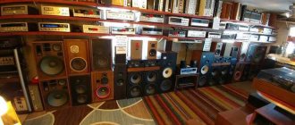
Bottom line
The wife knitted a napkin and the composition with Rigonda and the watch from the trash heap took on a finished look. Just completely vintage
. At the same time, the device picks up FM and serves as an excellent tube Bluetooth speaker. Plays very nicely.
Well, behind the green eye
very interesting to watch.
The entire column cost about 2,000 rubles and several days of time. If you want to repeat it, welcome to Avito :))) For just $100 you can put together such a cool thing.