The reason for this is the lack of a clear theory of mixing, and not of electrical filters, with them everything is clear, which cannot be said about mixing, where everything is based on nuances that are not properly described in the literature. The purpose of this article is to tell some of the features of filter design using a real example. In this article, unfortunately, there will not be a full-fledged calculation or instructions on how to take it and do it, because each case is unique and requires personal consideration, and at best, you can indicate what to pay attention to and set the vector of reflection in general.
Important speaker characteristics
First, let's figure out what the acoustic system is characterized by. There are three characteristics: amplitude, phase and impedance .
- The frequency response is considered the most important, since it determines the sound more, but happiness is not in it, an even frequency response is not a guarantee of good sound.
- The phase response itself is not audible; a sharp inflection of the phase at the separation point can be heard.
- IFC does not affect the sound at all, but it does affect the amplifier, but not every amplifier, but only one with high internal resistance, in particular tube ones.
Due to the impedance curve, many speakers may not be compatible with the lamp; all the impedance unevenness will appear in the frequency response. In some cases, this may be beneficial, but you shouldn’t hope for it, if only because such acoustics will be extremely sensitive to the amplifier, lamps and their modes will become audible, and comparison with a stone amplifier becomes completely incorrect.
Therefore, if you set a goal to build acoustics that are not very sensitive to the amplifier, it is necessary to ensure a constant impedance over the entire frequency range, and this imposes certain restrictions. In particular, this requires the use of filters tuned to the same cutoff frequency and having the same quality factor.
This rule allows you to control only the linearity of the impedance to adjust the filter, which eliminates the need to measure the frequency response of filters and in cases where there is no good microphone in measuring the frequency response of speakers, that is, you can get by with a minimal set of instruments: a generator (possibly software) and a voltmeter.
First lesson. Frame
First of all, let's limit the vast topic. Let's consider the development and configuration of two bandpass speakers with a bass reflex (FI). This type is easier for beginners. We agree that we will sound a living room of 10 - 20 m². This determines the choice of the diameter of the woofer/midrange speaker. In this case, the optimal diffuser diameter is 10 - 20 cm (approximately). Nameplate power (100 hours of one-time noise without damaging the speaker) - 20 - 60 W. Sensitivity - 86 - 90 dB/W/m. Resonant frequency (outside the housing) - no higher than 60 Hz. If you are satisfied with the lower limit frequency (of the finished speaker) of 100 Hz, you can take a speaker with a resonance of 80 - 100 Hz.
By the way, if the speaker reproduces at least 100 Hz without blockage, the sound is quite fundamental and “weighty”, only sometimes some optional, but very desirable elements of the sound picture disappear. They can be restored with a subwoofer, but in order not to spoil the sound, you need to gain experience in matching it with satellites.
Do not be fooled by the passport data of inexpensive speakers, which indicate low frequency reproduction from 30 to 40 Hz. In reality, only those low notes that are played without “clutter” participate in the formation of the sound picture. Anything that has a roll-off of at least 4 - 5 dB is masked by the “upper bass” (80 - 160 Hz), so for most speakers the audible range starts from 50 - 80 Hz. We are used to thinking that this is 30 - 40 Hz, since we are guided by the passport data with a permissible deviation of -8 - -16 dB. Take a closer look in the audio press at the actual frequency characteristics of the speakers. Measure out -3 dB from the average level according to the scale above, and you will see that even large floor-standing speakers operate effectively somewhere from 50 Hz.
If the diffuser diameter is 10 - 12 cm, sensitivity is 86 - 88 dB/W/m, and power is 20 - 30 W (typical parameters of an inexpensive speaker), then you will have to forget about the “home disco”. On the other hand, loudspeakers with a minimum diameter often have a more uniform frequency response than larger ones.
“Kids” are better in terms of width and uniformity of the radiation pattern. It is interesting that one of the highest quality speakers, System Audio, fundamentally uses only small midbass speakers. The total quality factor of modern small LF heads is usually 0.2 - 0.5.
Do not rely on low-frequency design calculations; practical results do not correspond to them accurately enough. Experience shows: it is better to choose speakers with a quality factor greater than 0.3 - 0.4, otherwise, even with a bass reflex, it is difficult to provide acceptable bass. For such loudspeakers, it makes sense to make cabinets with a volume approximately equal to the equivalent volume of the loudspeaker.
Very roughly, for speakers recommended in terms of parameters, the equivalent volume corresponds to the diameter: 10 cm - ≈ 18 liters; 16 cm - ≈ 26 liters; 20 cm - ≈ 50 liters.
As a basic option, we will consider a housing with a FI for a loudspeaker with a diameter of 16 cm. Volume - 26 liters. The cross-sectional area FI is 44 cm². The length of the FI pipe is 20 cm. The tuning frequency is about 40 Hz. The cross-sectional area FI should be 20 - 25% of the diffuser area SD.
Sd = π × (d/2)2, where d is the diameter of the diffuser, limited by the middle of the suspension (Fig. 1).
Rice.
1 If you need to recalculate the dimensions of the FI pipe for a different “displacement” (different speaker diameter), while maintaining the tuning frequency, proceed in accordance with the examples:
1. Loudspeaker d = 9 cm, Equivalent volume (Ve) ≈ 8 l. 8 liters is 3.25 times less than 26 liters. It is necessary to compensate for the difference by changing the length (l) and area (Sfi) of the FI pipe, otherwise the resonance frequency of the FI will sharply increase.
Reduce the tuning frequency Ffi by increasing lfi and decreasing Sfi. The optimal Sfi for a speaker area: Sd = π (9 cm/2)2 = 3.14 × (4.57 cm)2 ≈ 63.6 cm2 is in the range: Sfi ≈ 63.6 cm2/5 ... 63.6 cm2 /4 ≈ 13 cm2 ... 16 cm2. In this case, the decrease in Sphi contributes to a decrease in Fphi by 44 cm2/(13 cm2 ... 16 cm2) ≈ 2.75 ... 3.38 times, which completely compensates for the change in the volume of the AC by 3.25 times.
By the way, it is impossible to compensate for the decrease in volume by increasing the length of the FI pipe for a small body (V = 8 liters). Moreover, from the internal cut of the FI pipe to the nearest obstacle (to the wall of the speaker housing) there must be a free distance of at least 8 cm (in extreme cases - 5 cm). That is, one of the body dimensions (parallel to the axis of the FI pipe) should be equal to lphi (20 cm) + 8 cm (free space) + approximately 3 cm (thickness of the two walls of the body) = 31 cm./p>
For an 8-liter case, the size can only be so large in terms of height. A possible design of a slotted FI with a rectangular pipe cross-section is shown in Fig. 2a.
Rice. 2
This is a very impractical design, since it requires installation on a special stand that does not block the FI output. If you move the port to the top, the installation of the speaker will be simplified, but the view from above will worsen, in addition, the speaker will turn into an excellent trap for dust, debris and small objects.
The design shown in Fig. is very convenient. 2b. However, it requires increasing the height to 31 cm + 8 cm = 39 cm. This is not always acceptable.
It is possible to make a body in the form of a deep “loaf”, with the largest size being in depth (Fig. 2c).
If you cannot achieve the required pipe length, you can:
firstly, choose the minimum Sfi = Sd / 6; Sphi = 63.6 cm2 / 6 ≈ 10.6 cm2;
secondly, slightly reduce lphi (by ≈ 30%), sacrificing an increase in Fphi to ≈ 50 - 60 Hz.
Reducing Sphi to 10.6 cm2 will reduce the efficiency of the FI and, accordingly, increase the “impact roll” in the range of 40 - 60 Hz.
An increase in Fphi with a decrease in lphi is acceptable, since the resonant frequency of a speaker with a diameter of 10 cm is higher than that of a loudspeaker with a diameter of 16 cm. This means that a FI with a resonance of 55 Hz will not sum up its low frequency rise with the resonance of the speaker in the box (≈ 70 - 90 Hz in in this case) and there will be no increase in low frequencies harmful to the sound in the region of 50 - 100 Hz, which could arise, for example, when shortening the FI for a cabinet with a 16 cm speaker.
So, for an 8-liter box and a loudspeaker with a diameter of 10 cm, it is quite normal to choose lphi ≈ 14 cm, Sphi ≈ 13 cm2.
2. Loudspeaker d = 18 cm, equivalent volume (Vе) ≈ 50 l. 50 liters is 1.92 times greater than 26 liters.
Optimal Sfi for speaker area:
SD ≈ 3.14 × (18 cm / 6)2 ≈ 254.3 cm2
is in the range
Sphi ≈ 254.3 cm2/5 … 254.3 cm2/4 ≈ 51 cm2 … 64 cm2.
An increase in Ve by 1.92 times has a stronger effect than an increase in Sphi by 1.45 times. In general, Ffi decreases to approximately 35 Hz. Since the resonant frequency of a speaker (Fd) with a diameter of 20 cm is lower than Fd with a diameter of 16 cm, a decrease in Ffi is a positive factor. There is no need to compensate for this by reducing lphi.
Experienced professionals are able to accurately adjust the parameters of phase-inverted acoustic design, achieving the flatst possible frequency response in the range from the lower limiting frequency of the speakers to 125 - 200 Hz. An amateur or a beginner should not spend much effort on this.
In the future, I will explain how to control the resulting frequency response at low frequencies and how to eliminate unacceptable deviations, if any are found. In addition, the effect on the sound of imperfect characteristics in the low-frequency region strongly depends on the ratio of the level of bass reproduction compared to the mid frequencies. We must not forget that due to the interaction of the speaker with the real room, the frequency response in the lower register will in any case be very uneven.
The main efforts need to be focused on setting the desired frequency response in the midrange and balancing between low frequencies, midrange and high frequencies. At the first stage of creating a speaker system - when developing the case, it is enough to take into account the following recommendations.
The body must remain silent. Ideally, only the loudspeakers reproduce sound, but in real life, the body responds to their work. Re-emission of sound from the walls of the box introduces distortion.
One of the simplest ways to improve the vibration protection of a housing is to increase the wall thickness. Here you should know the measure; listening shows that starting from a certain value, this measure gives a slight improvement in sound. For bookshelf speakers, 16 - 8 mm chipboard or fiberboard will be quite sufficient. It is advantageous to strengthen the body from the inside with stiffening ribs.
Of course, there are many ways to protect speaker cabinets from vibration. They are given, for example, in the book “High-quality acoustic systems and emitters” (I.A. Aldoshina, A.G. Voishvillo. - M.: Radio and Communications, 1985.). Practice shows that 16-mm walls, reinforced with stiffening ribs, provide sufficient vibration protection.
There are no absolute truths. There is an alternative to acoustically dead cabinets - the use of solid wood of various types, each of which has its own sound. It's a difficult path with technological and creative challenges. It is not for beginners; it requires the highest qualifications in the field of woodworking, a subtle perception of music, and perseverance in finding acceptable options for the body. Sometimes it is possible to create excellent speakers this way.
Practical work
We smoothly move from theory to practice. I got vintage speakers called Kompaktbox B 9251. And the first thing that was done was listening.
With a cold stone, the sound was on average not bad, and if we speak specifically, in some places it was good, but in others it was haphazard. They refused to play with a warm lamp at all. Based on these observations, it was concluded that there was deep buried potential. An autopsy showed that German engineers decided to make do with one single capacitor in series with the RF head. The frequency response measurement gave a terrible picture. In the figure, the frequency response of one speaker, a curve with a deep hole at 6 kHz due to poor connector contact, do not pay attention to it. The frequency response of HF and LF separately is given below.
How to connect a tweeter through a capacitor
The RF head connection circuit, consisting of only one capacitor, is called a filter or first-order passive crossover. It's called "High-passfilter" and works like this. The capacitance of the capacitor determines the cutoff band. This does not mean that audio frequencies below the cutoff level will not be reproduced by the tweeter. A first-order crossover has a sensitivity of 6 dB (decibels) per octave. An octave is two times less or more. If the cutoff value is 2,000 Hertz, then a frequency lying an octave lower, that is, 1,000 Hertz will be reproduced with a level 6 dB less, a decrease in level by 500 Hertz will be 12 dB, and so on.
Based on the size and rigidity of the high-frequency loudspeaker cone, we can assume that low frequencies will not have a significant effect on the reproduction of the high-frequency range. There are more complex second-order crossovers, the circuit of which, in addition to the capacitor, includes a choke. They provide a power cut of 12 decibels per octave, and third-order filters provide a roll-off of 18 decibels per octave.
Crossover Frequency
Now is the time to think about the frequency of the section. Typically, the crossover frequency is selected in flat horizontal areas, away from resonances and blockages, trying to avoid sudden irregularities as potential sources of distortion... And if you remember that there is a phase about which little is known, and if it is known, then you can’t add up the vector frequency response on a piece of paper, but from - due to the curvature of the phases, even on a perfectly flat frequency response, something will come out, something will fail to a greater or lesser extent. You also need to remember what the speaker itself, especially the high frequency, can provide; for example, you shouldn’t force an inch dome to play from two, much less one, kilohertz, even if it is capable of playing them back according to the frequency response.
Don't forget that high excursion creates intermodulation distortion, so each speaker size has its own frequency range. In light of the above, the concept of crossover frequency is spread out over the area where it is worth mixing, and the end point is selected differently, for example by ear. Or not to select at all, but more on that later.
So, let's look at what unique speakers we got. The high-frequency driver begins to fall at 1.3 kHz, which means it cannot be allowed lower. On the other hand, the subwoofer tries to play at as low as 10 kHz, with varying degrees of success. However, common sense dictates that launching it above kilohertz is a bad idea. And what should you do if the operating ranges of the speakers do not intersect?
There are two options: if the declines have an adequate steepness, then it is best to drive into a hole, especially if the hole turns out to be wide. In our case, when the declines are as steep as cliffs, we must stay away from the steepest of them. Most often, this can happen with a high-frequency driver; it is always difficult for them to work at the lower limit of the range, so it is more expedient for them to make their life easier by entrusting the reproduction of the lower part of the range to a low-frequency speaker, which will play at least poorly, but will not spoil. Therefore, we limit the range to the area from 1.5 kHz to 2.2 kHz.
Labor lessons, or methods for creating acoustic systems
All amateurs and specialists interested in reliable sound reproduction know that they cannot do without good acoustic systems. Therefore, the contradictions between different views on the quality criteria of speakers are especially puzzling. It is even less clear which methods of creating speakers are more reliable and lead to acceptable results.
Even initial listening experience is enough to notice a very big difference between the sound of the same music on different models. At the same time, the main parameter - the amplitude-frequency response (AFC) - is almost always close to ideal, according to the data of the manufacturing companies.
Most music lovers cannot independently measure the frequency response and come to the conclusion: the problem of frequency response is practically solved, the quality of sound reproduction depends on the design and materials of the speakers, cabinets, and crossovers. For example: a coil without a core is good, with a core - worse. Or: a body weighing 40 kg is better than a 20 kg one, with the same dimensions, etc.
Of course, it would be a mistake to dispute the influence of speakers, cabinets, crossover elements, internal wiring cables, sound absorbers and other components, but is everything okay with the frequency response? Independent measurements, for example, in well-equipped laboratories of reputable foreign and domestic audio magazines, do not confirm the optimistic parameters declared by the manufacturers.
In practice, each speaker model has its own frequency response curve, which is strikingly different from other types of speakers, and this applies to any price group. The observed difference many times exceeds the threshold of noticeability known from psychoacoustics; it is simply impossible not to hear it. And listeners, of course, notice it as a difference in timbral balance when playing the same compositions with different speakers. It is not easy to identify timbre distortions with problems of frequency response uniformity, because before your eyes are even, as if drawn on a ruler, characteristics from the manufacturer.
It’s not a fact that these amazing graphs are a hoax. Just for advertising purposes, measurements are made using methods that ensure a “pretty” appearance of the curves. For example, with an increased scanning speed of the operating range in combination with high inertia, that is, averaging of peaks and dips when recording the dependence of sound pressure on frequency.
Manufacturers can be understood; after all, we all want to look a little better than we really are, and that’s why we comb our hair, wash our faces, etc. before important meetings.
Something else is much more interesting: why does one speaker with a “bad” frequency response sound good, while another, perhaps with a less ugly characteristic, sounds much worse? Independent, more “honest” measurements reveal imperfections in the transmission of timbral balance due to the characteristics of the frequency response, but do not help interpret, decipher the meaning of “kinks” and imbalances in characteristics, or reveal the connection between the behavior of the curve and specific features of the sound of the speakers. Here is a suitable comparison: a cardiogram does not tell an ordinary person anything, while a medical specialist is able to read the patient’s condition from it.
Our task today is to learn how to analyze the frequency response. Let's start with the most general question. Why, having everything they need, don’t developers create ideal, equally good-sounding acoustics? After all, there is only one ideal, a standard! Obviously, all speakers close to it will sound very similar. There are a number of generally accepted methods for ensuring a “flat” frequency response, and one of the main ones is tuning the speakers in an anechoic chamber. There are other, seemingly logical and adequate methods, for example, tuning using pulse signals. But working using the same algorithms, specialists get different results every time. Remember the revelations of authoritative foreign masters, published in the audio press: “... having provided an ideal frequency response in the sound-measuring chamber, we then “spoil” this characteristic to obtain acceptable sound under normal conditions...”. Isn't it time to stop praying for the uniformity of the frequency response from the point of view of some well-known measurement technique?
After all, any method of measurement in science and technology inevitably produces a whole complex of various types of errors. In our case, the most harmful errors are methodological, that is, related to the imperfection of the approach itself. For example, where should the microphone be placed relative to the speakers in the sound chamber? On the acoustic axis? Where is this axis? In front of the tweeter? What if it plays starting at 8 kHz? Then, apparently, it is more accurate to measure on the axis of the midrange speaker? What if you move the microphone 5 cm higher? We get a completely different frequency response. Which one should you focus on? And why do we think that the listener's ear will be exactly where the microphone was?
In addition, at the low end and lower middle, the speaker actively interacts with the floor, the influence of which is absent in the anechoic chamber.
We won’t even start talking about the integration of speaker radiation with the listening room at this moment. This interaction greatly affects the sound, but its specific manifestations are infinitely diverse, and therefore do not fit into the “bed” of any mathematical model with sufficient accuracy required for truly high-quality reproduction.
Another interesting fact: in a real room, the total frequency response of two speakers in a stereo pair, even with strong averaging, is very different from the frequency response of one speaker. Traditional methods for setting up speakers do not take this important circumstance into account. This is unacceptable, since the main people in music - soloists - are most often localized in the center of the sound stage, that is, they are reproduced by both speakers.
We can conclude: with such an abundance of methodological errors, conventional methods of monitoring the frequency response give an incorrect characteristic for really very smooth speakers (for example, Audio Note, Magnepan, etc.). On the other hand, overly smooth frequency responses obtained using unreliable methods look extremely suspicious. In this case, measurement errors are compensated by a specially formed characteristic, which the developer provides, blindly trusting measurement methods that have not proven themselves in practice.
The last thing I would like to do is replace faith in some imperfect principles with faith in others, mine. They are also far from ideal; they contain noticeable methodological errors, only less gross.
The key to progress is an understanding of the fragility of the role of achieved knowledge and skills, a willingness to perceive, in the process of practical work and research, new discoveries. You must be able to reconsider approaches to achieving better results if quantitative growth allows you to make a qualitative leap.
The result of the work depends on the methods and personality development of the creator of the speaker. There are excellent products born within the framework of traditional approaches, subject to the highest class and experience of the developers.
My goal is to equip everyone with a fairly effective technique for creating speakers with acceptable sound. The long introduction was necessary in order to draw your attention to the factors that hinder the development of the art of speaker tuning.
I would like to convey my experience without spending exorbitant “writing” efforts on it. Therefore, I will only talk about facts and methods of work obtained in practice, without justification or theoretical explanations. My principle is that you can confidently express your opinion if you have an audio system that confirms the author’s recommendations with good sound. For accessibility, calculations and setup techniques are simplified as much as possible, without significant harm to the result.
Filter order and quality factor
The next parameter that you need to decide on is the order of the filter and its quality factor. This article will consider two orders, first and second.
- With the first, everything is simple: there is a coil, there is a capacitor, we calculate their parameters for the required cutoff frequency and, if necessary, adjust the values until the desired frequency response, phase response, and frequency response are obtained.
- The second order is trickier, there are already two coils and two capacitors. A parameter such as the quality factor depends on the values of the nominal values; it determines the steepness of the frequency response decline and, to some extent, the phase shift. Since the influence of the phase shift and slope cannot be speculatively estimated, all that remains is to simply choose which way to think. And think here in the direction of low quality factor, read more inductance in the coils, less capacitance in the capacitors.
How to choose an order. Here we are guided by already familiar considerations about what emitters, especially high-frequency speakers, are capable of. If a big move is contraindicated for him (as in our case), then we give preference to the second order.
To complete the picture, it should be mentioned that the order also determines the degree to which the speakers work together, but this is information for independent reflection.
Acoustic crossover - DIY circuits for audio speakers and subwoofer
Making a homemade acoustic crossover used in home speakers or subwoofers with your own hands is not difficult. Of course, for this you need to have at least some skills and straight hands.
Why do you need an acoustic crossover in a sound system?
This electronic device is assembled according to the type of filters and plays an important role in acoustics. And it is designed to divide the signal coming from the source into several operating frequency ranges using the speakers used. The crossover practically performs the work of a filter by filtering out unnecessary frequencies, thereby filtering the entire audio path.
Connecting a crossover to a speaker
A simple example here are high-frequency speakers called tweeters. So, if acoustic crossovers had not been installed in the audio speakers, the tweeters would simply have been overwhelmed by the entire spectrum of midrange and especially bass frequencies pouring into them. It is clear that in this case there is no need to talk about any detailed sound reproduction. Dynamic high-frequency drivers cannot reproduce frequencies other than high frequencies.
What are the types of crossovers?
Audio crossovers are special electronic devices as part of acoustic systems; they come in active and passive types, two-way and three-way.
Pros and cons of a passive frequency filter
A passive frequency filter filters audio signals using on-board resistors, capacitors and speaker inductors. Ultimately, these electronic elements lose a lot of useful power going to the speakers. This is precisely the weakness of passive acoustic crossovers.
Installation and connection of the frequency filter structure in speakers is usually performed at the closest point from the speaker.
It follows from this that with this option, only one power amplifier is enough to get high-quality sound. This scheme of using a passive filter indicates its positive side in the operation of acoustics.
Acoustic filters are commercially available both as separate modules and as built-in acoustic filters, usually designed for two or three passbands. The disadvantages of such passive electronic devices include their inability to withstand prolonged maximum load. In the case of long-term use of a passive crossover in peak load mode, it is fraught with failure.
Active acoustic crossover, its pros and cons
An active type audio crossover is installed in the input circuit of the power amplifier, that is, at its input. For this reason, using only one amplifier, as in a circuit with a passive filter, simply will not work. Using an active filter device in an audio system means providing each speaker with a separate signal amplification path, regardless of the frequency it uses.
An active crossover, as opposed to a passive one, has the ability to correctly select and precisely adjust the cutoff frequency. In particular, it is this function in the device that is considered the most valuable in terms of creating high-quality sound.
Speaker impedance characteristic
When everything is more or less clear with the approximate parameters, it’s time to move on to practice. We take the impedance characteristics of the speakers. In order to estimate the resistance, the graph has a ladder in steps of one ohm. A jump at 110 hertz is a switch from 10 ohms to 20.
Of course, with such humps, not a single filter will work normally, and especially not a low-pass filter. In general, this rise does not interfere with the work of the high-pass filter, however, as mentioned earlier, such a rise at the end of the range will lead to a rise in high frequencies if the amplifier has a high resistance. This can also be used for good, leaving the rise small.
To level these rises, the so-called Zobel chain is used. It consists of a resistor and a capacitor connected in series. The easiest way to select it is by scientific poking: take a rheostat, a handful of capacitors, and move it all until you get a straight line.
For an approximate idea of what depends on what, I provide a set of graphs for various capacitances and resistances. The step starts at 10 ohms.
Knowing the minimum resistance of the low-frequency link, you need to bring the high-frequency link to the same. There are many options for how to connect two resistors and a Zobel chain, and anyone who has decided to take such a brave step as mixing is able to determine the type of connection and resistor values, so it is unnecessary to describe this procedure here. Specifically, in these speakers, based on the results of preliminary listening, it was decided to leave the original 2.2 ohm resistors and the Zobel circuit parallel to the tweeter.
DIY acoustic frequency filters
Sometimes it happens that the car owner is not satisfied with the standard acoustics and decides to replace it with a cooler one. But when installing it in a car, it turns out that this expensive audio system is not equipped with crossovers. In this case, of course, it will not be possible to obtain a high-quality sound picture. Why not, because without frequency filters, the tweeters will simply fail, and without them it is no longer sound.
There are only two ways to solve such a problem, and thereby get out of this unpleasant situation - to purchase crossovers separately in a store or to make them yourself. By the way, there is nothing complicated about this, you just need to carefully read the instructions for making such devices. If you choose the option of making frequency filters for speakers yourself, you will need the appropriate materials and tools.
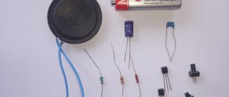
What materials and tools are needed:
- Normal powerful soldering iron
- Varnish for impregnation of coils
- Ferric chloride for board etching
- Fiberglass based fiberglass
- Heat shrinkable tubes
- Silicone sealant
Device for measuring the inductance of coils
Acoustic crossover - successive manufacturing steps
Before starting work on installing a frequency filter, it is advisable to become thoroughly familiar with the technical parameters of the speakers you purchased. One of the most important criteria is the frequency range of the tweeters, which is usually in the range from 2 to 30 kHz. Next you need to find out the sensitivity of low-frequency and high-frequency emitters. It is based on these characteristics that you should select a sound circuit with a crossover connection.
Note. As professionals advise, it is best to install second-order crossovers in cars. Structurally, they are assembled using one capacitor and one coil for the tweeter and the same set for the woofer. This scheme has higher sensitivity.
Inductors for audio speaker filters
If you intend to make coils for low-frequency loudspeaker filters, then winding is best done with copper enamel wire with a wire with a diameter of 1 mm. You need to wind the coils using the ordinary method, turn to turn and in several rows; upon completion of winding, so that the turns do not spread out, they need to be fixed with glue.
Then, after winding, be sure to check the resulting inductance of the part using an RLC meter or a digital multimeter with an inductance measurement function. Subsequently, when all the coils are ready, they need to be placed in a small container with varnish (any kind can be used, even construction grade). After this, let the varnish drain and dry them.
Useful recommendation. When forming, it is advisable to use ferrite cores. On a ferrite rod, the overall resistance of the coil is significantly reduced, and the design itself is quite compact. In addition, the number of turns is reduced, which means less copper wire consumption.
Making a printed circuit board for an audio crossover
The printed circuit board for the acoustic filter itself is very simple, since large parts will be installed on it, so the conductor tracks will be wide. First, the diagram is drawn on paper, marking the attachment points of the parts corresponding to their sizes, that is, for coils, capacitors and resistances, as well as contact pads for connecting connectors.
After the diagram is drawn on paper, it must be attached to a pre-prepared fiberglass sheet based on copper foil and with an awl, through the paper, mark the installation points of the components on the foil. That is, you will need to drill holes at these points.
When you finish drilling, you will need to decide what method you will use to make tracks and pads on the board. If you choose the etching method, then you will need to paint over the conductive conductors and soldering pads for the leads of the parts, let the paint dry, and then etch it in a ferric chloride solution.
There is another option for making a board: mark with a pencil on the foil all the necessary places for soldering the parts, and between them with a sharp tool, cut lines along the foil all the way to the PCB so that the contact pads do not touch each other. Well, the third option, the so-called “collective farm” method - it is shown in the video below. In general, as you like, depending on your capabilities and abilities.
Making your own filter for acoustics
Note. All components installed on the board must be securely fixed with good glue and, in addition, tightened with nylon clamps. Such careful fastening is caused by the need to install the crossover inside the audio speaker, and not outside. And if the parts are poorly secured to the board, they will simply be torn off by dynamic shocks inside the case. Maybe not right away, but it will definitely come off.
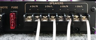
Installation of acoustic wires
Connecting the wires is done using a soldering iron, there is nothing complicated here, the main thing is not to mess up the connection so that the woofer speaker wires do not go to the tweeter, and at the same time maintain the polarity. In addition, the acoustic wires connected to the filter, as well as the components on the board, must be firmly fixed with glue so that they do not dangle.
The recommendations and tips presented here for making an acoustic crossover will hopefully help you in assembling this device yourself. The budget for this device depends on the complexity, quantity and quality of the elements used.
Source
Flattening filters
Now the final stage begins - mixing the filters. It's time to wind the reels... or not to wind them? You are always too lazy to wind, there are no wires, frames, or specific inductance values. In view of these reasons, after searching in the trash, we found pairs of 0.8 mcg and 3 mcg coils - we had to build on them. In extreme cases, you can always rewind or unwind the excess.
The graph shows that the section fell into the region of 1.8 kHz, which fits well within the intended boundaries. By selecting capacitors we managed to achieve the following impedance. There are two bumps at the crossover frequency, but their height is less than half an ohm - this is not critical. This is not its final form; subsequently the resistor in the Zobel circuit of the tweeter was slightly increased.
The above pictures show the frequency response of both the filter itself and the frequency response of the speakers with it turned on.
Speaker phasing
This brings the mixing to an end. All that remains is to decide on the phasing of the speakers. There are at least three ways: by ear, by the shape of the frequency response and by the phase shift at the crossover frequency. If the speakers have a moderately linear frequency response and phase response, and the filter does not greatly increase the phase at the crossover, then when the correct phase changes to an incorrect one, a deep dip will appear at the crossover frequency, it is difficult to miss it. In this case, it is worth adjusting the phase according to its shift. This can be done with an oscilloscope by feeding the horizontal deflection signal from the amplifier, and the vertical deflection signal from the microphone.
A sine wave with the crossover frequency is supplied to the amplifier input and, without changing the relative position of the microphone and speakers, the high-frequency and low-frequency speakers are switched. Based on the similarity of the Lissajous figures, a conclusion is drawn about the equality of the phases of the emitters. This method works well for first order filters. With the curvature of our speakers, this method does not justify itself, so we compare the frequency response at different phasing.
The second option is noticeably worse. However, the first one is not the ultimate dream, but since moving the inductance of the coils is not easy, and it’s too lazy to tinker further, everything was left as is.
Scheme
The input signal is fed to the non-inverting input of the operational amplifier MC1, which serves as an active low-pass filter with a frequency response slope of 18 dB/octave, and to the non-inverting input of the operational amplifier MC2, which functions as a differential amplifier with a voltage gain Ku=1.
The inverting input MS2 is supplied with a signal from the output of the low-pass filter MS1. In the differential amplifier MC2, its low-frequency part is subtracted from the spectrum of the input signal, and only the high-frequency part of the input signal appears at the output of MC2.
Thus, you only need to provide a given cutoff frequency of the low-pass filter, which will be the crossover frequency. The values of the filter elements are found from the relations C1 = C2 = C3; R1=R4; R5=R1/6.8; R1C1=0.4/Fp, where Fp is the crossover frequency.
I took R1 22 kOhm, and then everything is calculated using formulas depending on the required crossover frequency. I tried K157UD2 and K1401UD2 as operational amplifiers, both showed good results. Of course, you can use any quad imported op-amp.
Filter assembly
In conclusion, a few words about the assembly. The filter uses relatively large capacitances, 20 µF, 27 µF, and there is not much space in the case; there is not enough paper or film. You have to put in electrolytes. And if in a low-pass filter the sound does not suffer much from their use, and in the main circuit they may not be heard at all, then in a high-pass filter it is dangerous to neglect the sound of capacitors. It is for this reason that paper MBGO and film K73-16 were used, and all electrolytes were shunted with paper MBGO at 4 μF.
You should not get carried away with paralleling very different capacitors. The main criterion here is the loss tangent. If, for example, you put audiophile polypropylene in a shunt to a paper capacitor, then most likely the tops will come out and they will be acidic. Probably, here we can draw an analogy with internal resistance, comparing the loss tangent with it: the smaller it is, the more signal will pass through the capacitor, and since the capacitance of such a high-quality capacitor is smaller, only the high-frequency part of the signal will pass through it, hence we have increased levels top But this is only an analogy for a better understanding of the effect of shunts on sound.
There are plenty of articles written about how to distribute the coils and what thickness of wires to use; I will not repeat them here. It’s easier to show a picture (here the high-frequency driver socket is soldered incorrectly, it should be after the resistor).
Application
It is quite varied. High frequencies are used in telecommunications. Low frequencies are used in data collection devices. They are also used in musical instruments to eliminate noise and change sound.
To suppress frequencies close to the mains frequency, they are used in power supplies. In industry they are used as harmonics and compensate cosine phi.