Background
I think many of you have not only heard, but also directly encountered such a platform as Arduino.
And as my personal statistics show, very few people go further than blinking LEDs. When I got acquainted with Arduino for the first time, I was stopped by the fact that I had no idea how exactly I could use all the capabilities of the same UNO to its fullest. It was only enough to assemble a simple robot on two wheels and an alarm system. At the same time, I wanted to do something more thorough. Then I remembered my childhood, in which there were so-called “radio constructors”. A harsh Soviet DIY Kit, which, with proper assembly and proper soldering, even began to work and picked up radio stations in various bands: Yunost, Elektron-M and others.
I didn’t get any of these Kits, but I did get EKON-1:
The main “trick” of this designer was that with its help it was possible to quickly and easily assemble a large number of different devices, from simple “tweeters” to a fully-fledged radio receiver. ECON-1 is one of the many reasons why I ended up in the IT field in the first place. And it occurred to me that it would be nice to create a modern version of such a construction set, so that everyone could enjoy the device they had just assembled with their own hands.
FM radio receiver on one chip (CXA1238S).
It so happened that one day, one person wanted to assemble a good FM receiver with his own hands. A suitable option was quickly found on the website radioshema.ru The circuit is (as it later turned out) a modification of the version proposed by the manufacturer of the specialized chip CXA1238S (can be found by typing “datasheet CXA1238S” in a search engine). Two transistors were added to the original circuit, one as a UHF amplifier, the second as an IF stage. In addition, the circuit of the input circuit and local oscillator has been changed, namely, instead of variable capacitors, varicaps have been used.Attached to the diagram was a drawing of the printed circuit board.
After a long period of manufacturing work, the long-awaited moment arrived - the receiver was ready for testing.
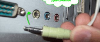
After applying power and connecting a suitable piece of wire as an antenna, the circuit came to life. The receiver definitely worked, but not quite as expected. He only picked up one radio station, and the sound quality was completely unimportant. The setup tips (quite detailed, I must say) did not give a positive result. Of course, questions arose about the performance of the proposed scheme. Upon closer inspection, the tuning circuit caught my attention. It turned out that with its help it seems completely impossible to rebuild anywhere .
After all, in order for the capacitance of varicaps to change, it is necessary to apply at least some voltage to them.
And here, there is a plus
from the reference voltage source (marked in red in the figure) of the microcircuit, but
no minus!
Looking on the Internet and browsing thematic sites, we were able to discover more viable options, such as a version of the original manufacturer’s circuit (SONY) or, for example, this circuit (site “Dinistor.net”).
As you can see, everything is fine with the settings here. Voltage is supplied to the varicaps. It is changed using resistor R12. As you yourself understand, there was no point in completely redoing an almost finished circuit; amendments were made to the configuration circuit (surround mounting). After that everything worked great. The receiver picks up almost all FM radio stations broadcasting in our region. The sound quality is quite high, although the frequency response of the AF path has a noticeable bias towards higher frequencies. With the help of the circuit R14, R14*, the captured radio station is retained; the effect increases as the resistance of resistor R14 decreases and accordingly weakens as it increases (about 400 kOhm is selected). Personally, I would recommend that everyone use the option with “Dinistor.net” (for obvious reasons). The circuit does not contain rare or expensive elements.
IF filter (10.7 MHz).
Electrolytic capacitors:
The remaining capacitors are ceramic:
| C2 - C6, C8, C10, C23 - C12, C22 - C15, C20- C17, C19- C21 - C24 - C25 - C26 - C27 - C* - | 0.47uF 10-15nF 0.1uF 1nF 10pF 10-56pF 15pF 180-220pF 33pF 3-5pF 0.1uF |
Resistors:
| R1, R13 — R2 — R3, R7 — R5 — R6 — R8, R9,R12 — R10 — R11 — R14 — R14′ — | 2.2 kOm 10 kOm 6.8 kOm 680 Om 100 Om 100 kOm 3.3 kOm 220 Om 100-680 kOm 100 kOm |
Contour coils L1, L2, L4 - are wound on a mandrel with a diameter of 3 mm (ballpoint pen rod) with PEL-0.5 wire. Any variable resistor can be used as resistor R12. But it is better to use a multi-turn one (such resistors were used in old TVs, in the program selection block).
Filter ZQ1 can be replaced with such a circuit.
Scheme for replacing filter L3 - 10... 14 turns of PEL-0.5 on a frame with a diameter of 5 mm with a tuning RF core. Assembly and adjustment of the device: With a supply voltage of 2... 7.5 V, a jumper should be installed instead of the voltage regulator DA2. The LF signal level at the output is no more than 250 mV; to tune the tuner “by ear” you must use any suitable AF amplifier. Tuner settings should be carried out in an area of reliable reception, in the following sequence:
1. Input circuit L4, C26 is not installed; 2. With circuit L1, C17, the local oscillator is tuned to receive any powerful FM station; 3. Circuit L2, C19 adjusts the UHF at maximum volume; 4. The circuits are adjusted by compressing or stretching coils L1, L2 or changing the number of turns; 5. When replacing the ZQ1 filter with an LC circuit, it must be tuned to resonance at a frequency of 10.7 MHz. By ear, this is determined by the minimum distortion and maximum volume; 6. By moving the slider of the adjustment resistor R12 to the extreme position, adjust the local oscillator frequency with circuit L1, C17 until the range is completely covered; 7. Use resistor R4 to adjust the VCO frequency until the pilot tone is reliably captured, which is determined by the ignition of VD1 when receiving stereo broadcasts (switch SA1 is open); 8. Install the input circuit L4, C26 and adjust it to the maximum volume of stations located at the edges of the range;
It is recommended to repeat the setup when the signal is weak to obtain maximum reception quality. After completing the adjustment, the turns of the coils must be secured with cotton wool soaked in paraffin. If, even after the final setup, noise remains when receiving powerful stations, it is recommended to ground pins 19, 24 to the common wire through capacitors with a capacity of 0.1 μF (indicated C* in the diagram).
During operation, a flaw in the operation of the AFC was discovered: uneven action of the AFC from the center of the range to its edges, so it is recommended to remove the resistor R14 and replace it with the chain R14′, and C27 (in blue in the diagram). Capacity C27 - determines the degree of tuning retention at the station. You can expand the overlap range of the tuner by reducing the capacitance or removing capacitors C17 and C19. In this case, you will need to re-adjust sections of the range, adjust the local oscillator (L1-6 vit.), adjust the UHF (L2-7 vit.), adjust the input circuit to the middle of the range (L4), you will need to change the number of turns of the loop coils. It should also be taken into account that it is advisable to carry out all settings in the middle of the RF range. The capacitance of capacitor C27 must be reduced to a value of 1 ... 3 pF. On the 12th pin you can “hang” an LED relative to the “+” power supply, through a current-limiting resistor similar to R5.
Prototype on circuit board
My friend, the talented engineer Konstantin Tomarevsky, supported the idea, and we began to think about how to make the first prototype.
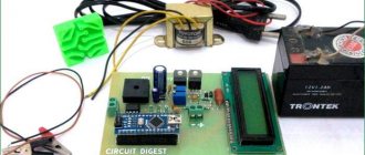
The idea was to create an FM receiver that could be controlled via an MK. The first prototype was assembled on the assembly line, and it became clear that it works
For the very first version, the following components were selected:
1. MK Atmega328P-PU 2. RDA5807M 3. Nokia 5110 display
Such a microcontroller is used in Arduino UNO; accordingly, our device is compatible with UNO at the hardware level.
RDA5807M is the “heart” of our designer. This tuner has the following features:
- CMOS technology - Monolithic package, does not require external components (almost) - Frequency band: 50-115 MHz - Channel pitch - from 200 to 25 kHz - RDS/RBDS - ADC and built-in frequency synthesizer - Adaptive noise reduction - Digital interface ( I2C) - Signal level (RSSI) - Amplifier - Audio volume control
Nokia display is black and white, 84x48 pixels. It is very easy to connect and control.
After soldering on the circuit board it turned out something like this:
It was decided to use Bootloader from Arduino, this made it possible to maintain compatibility with all numerous libraries and significantly reduce the entry barrier for those who already had some experience with the platform. The user interaction interface is implemented as follows. Three buttons connected to the analog input of the MK through resistors are used to switch modes and control the receiver. Another button is used to reboot the MK. The screen accordingly displays information about volume, station, etc.
Arduino Programming
The Si chip in this design is an I2C slave device with a fixed address of 0x11; in this case, the master device (master) is the Arduino board. However, the I2C communication speed of this chip is relatively slow: the maximum supported speed is 50 kHz. In addition, during the power-up procedure, the speed should not exceed 10 kHz. To meet these requirements, we must explicitly set the Arduino to I2C speed, which is generally too high for the Si4844-A10. Luckily, thanks to the wealth of documentation on Arduino's I2C functions, we can easily make the necessary changes.
Basically, the I2C speed for our purposes is determined in the Arduino software by two variables. These variables are TWBR and TWSR. TWSR bits 0 and 1 control the prescaler, which operates on the TWBR value to set the I2C speed. The I2C transmission speed (clock frequency) is calculated using the formula:
Frequency = CPU clock speed / (16 + (2 * (TWBR) * (prescaler))
Arduino Pro mini 3.3V operates at 8 MHz. To set the I2C speed to 10 kHz, we use a TWBR value of 98 and set the prescaler to 4 (by setting only TWSR bit 0 to 1). Thus,
8,000,000 / (16 + (2 * 98 * 4)) = 10,000 or 10 kHz
To set the I2C speed to 50 kHz, we use a TWBR value of 18 and set the prescaler to 4 (by setting only TWSR bit 0 to 1). Thus,
8,000,000 / (16 + (2 * 18 * 4)) = 50,000 or 50 kHz
For more details, see the Wire library documentation for Arduino. The point is that we can perform the I2C speed change with just a couple of lines of code, which you can see in the test program.
Another important point related to programming is that we need to use an external interrupt routine in our code. We use INT0 on the Arduino, and when the Si4844-A10 sets this pin to 1, a simple function that is tied to this interrupt will be executed. All this function does is change the value of a flag variable, which can be checked and changed in other parts of the program. The Si4844-A10 will trigger interrupts (i.e. drive a logic one level to the INT pin) under certain conditions, mainly when the resistance of the tuning potentiometer changes. This is how the Si4844-A10 tells the Arduino that you have turned the dial and that the data on the display needs to be updated.
LUT, photoresist and debugging
After successful tests on a circuit board, we decided to create several more prototypes using the LUT method (and later using photoresist).
We also decided to improve the receiver by adding another sound amplifier to connect not only headphones, but also an external speaker. The choice fell on the PAM8403; it is a simple and inexpensive amplifier that requires a 5V power supply. The first prototype made using the LUT method looked like this:
LUT is a good thing for relatively quick prototyping at home, but when it comes to double-sided boards, things get tricky. The number of components on the board increased - for example, we decided to place a connector for the programmer on the board so that there was no need to remove the MK each time for flashing. So, the subsequent prototype became double-sided, was made using photoresist and began to look much nicer:
In the assembly:
The next step was to abandon the “add-on” components that we placed on the board using single-row PINs. So, it was decided to replace the amplifier with an LM386N and install a CD4050BE level converter. All this complicated the design, but the device began to look much better.
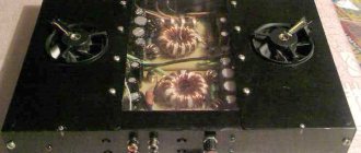
The final prototype we made at home looked like this:
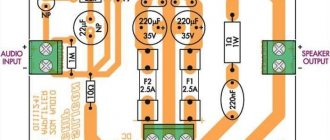
Audio amplifier
An audio amplifier is a device that amplifies weak audio frequency signals to the level necessary for normal operation of a loudspeaker (speaker). For our project, we designed an audio amplifier based on the LM386 chip, its circuit is shown in the following figure.
Ordering printed circuit boards
In China you can order industrial printed circuit boards.
The cost is relatively low even for small print runs, and the waiting time (including delivery) usually does not exceed 2-3 weeks. The first “batch” of boards was ordered from PCBWay. This is what she looked like:
One of the problems that we encountered due to our inexperience: the metallization “eats” a significant part of the size of the hole itself, so some components had difficulty “fitting” into the required holes. When designing a circuit, this point must be taken into account.
Based on the testing results, we further refined the design, adding several capacitors for more stable operation of the device. We assembled another prototype:
The USB connector is used to power the receiver. Power is also supplied when the programmer is connected.
Everything is working!
Firmware
It’s worth mentioning the firmware separately.
It is written in C++ and we distribute it under the GPLv3 license: https://github.com/xtremespb/fm_receiver. I have practically not developed in C/C++, so (probably) the code is far from ideal and may contain errors, but the GPL is for that and GPL so that it can be further developed by the community. Current firmware features include:
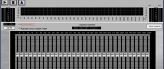
— Manual and automatic tuning of stations — RDS — Volume control — Enabling the enhanced bass mode — Turning the display backlight on and off — Displaying and dynamic visualization of the signal level
In the next, fourth revision, we will make a few more useful “tricks”: we will connect the left and right channels to the analog inputs on the MK, which will allow us to “visualize” the incoming audio signal.
By the way, the device’s capabilities are not limited to radio! No one is stopping you, for example, from writing some kind of game (just for fun, I made the good old Arkanoid) or another program that uses the board’s capabilities.
Programming Si4844-A10
Essentially, the Arduino sends commands to the radio chip over the I2C bus, then the chip performs the requested actions and returns status information. The Si chip can operate in several modes, which allows you to configure the exact frequency and desired parameters. In this project we use the Si4844-A10 chip in a mode that accepts predefined (or standard) RF bands with default parameters. This mode was chosen because it provides easy access to basic functionality while still offering a degree of customization.
Instead of simply setting the MF/HF/VHF “register” value, the radio chip can select one of 41 different frequency bands. Bands 0–19 – ultrashort waves (FM) 87–109 MHz; bands 20–24 – medium waves (AM) 504–1750 kHz; bands 25–40 – short waves 5.6–22.0 MHz (SW). These ranges vary in width, which can make adjustments difficult. Moreover, the frequency ranges of several programmed bands are equal or differ slightly, but have different parameters, for example, pre-emphasis (VHF/FM), channel width (MF/AM), stereo separation thresholds (VHF/FM) and received signal level. To fully understand this, you must refer to the data sheet and application notes, where you can see the range tables, as well as all modes, programming commands, and response and status formats.
In this project, the software will provide access to all standard bands, as well as control of basic parameters including mode changes (AM/FM/SW), volume, tone and mute.
Production
The development of the device from idea to implementation took about 6 months, which, with almost a complete lack of experience in this area, is not so bad.
We currently have about 10 fully assembled kits that include everything you need to build your own device:
— Atmega328P-PU MK — CD4050BE level converter — Nokia 5110 display — RDA5807M receiver — USBasp programmer — LM386N operational amplifier — Connectors for the MK and programmer — USB B, Audio Jack 3.5, three buttons, wires, single-row connectors — 11 resistors and 12 capacitors , 4 inductors, quartz, zener diode and LED - Speaker - Printed circuit board
For assembly you will need solder, flux and a soldering iron, nothing else is needed. All components are packed in a small box made of “craft” cardboard:
The firmware sources have already been posted on Github; The Gerber file, schematic diagram and assembly instructions will also be published later.
Adding a Keyboard
To control the radio receiver we need an input device. For our purposes, a simple membrane keyboard is sufficient. They are easy to connect to Arduino. Below is an illustration of the keyboard pin assignments (rows and columns) that I used, you should make sure your keyboard is similar.
Simple Membrane Keyboard
Connecting Keyboard to Arduino
| Keyboard | Arduino |
| Line 1 | D8 |
| Line 2 | D9 |
| Line 3 | D10 |
| Line 4 | D11 |
| Column 1 | D13 |
| Column 2 | D14 |
| Column 3 | D15 |
In the software I used a library from Mark Stanley and Alexander Brevig, which is released under the GNU General Public License. For the project, we will map functions to buttons as shown below.
Assignment of buttons to control the radio receiver
Purpose of keyboard buttons:
- AM: switch to AM (medium wave) mode, band 22;
- FM: switch to FM (ultra-short wave) mode, band 8;
- SW: switch to SW (short wave) mode, band 31.
Please note that the standard ranges for changing the mode are configured in the program and can be easily changed. Additionally, the current volume and tone settings will be carried over to the new mode.
- Vol+ / Vol- : Increase or decrease the volume by one step. There are 64 volume levels. Since the project uses speakers with a built-in amplifier, these buttons are not very important, but their presence is still nice;
- Band+/Band- : Change the band by one step, but from those available in the current mode;
- B/T+ / B/T- : Increase or decrease the tone by one step. I admit that I use the term “tone” somewhat loosely. For FM mode, this will increase or decrease the bass level from 0 (max bass) to 8 (max treble). For AM/SW modes, this will set the channel filter from 1 to 7. The filters are 1.0 kHz, 1.8 kHz, 2.0 kHz, 2.5 kHz, 2.83 kHz, 4.0 kHz and 6.0 kHz respectively. Also note that for simplicity and convenience of programming (i.e. laziness), levels 0 and 8 can be added to AM/SW modes, but they will not be different from levels 1 and 7 respectively;
- Mute: Turn the output sound on or off.