When designing and constructing guitar preamps and combo amplifiers, the question often arises of which tone block to use. The purpose of this article is to introduce the reader to possible options.
Here are the passive tone
used by famous guitar electronics brands such as
Fender, Marshall and VOX
. From the simplest with one regulator to three-way ones.
↑ Marshall JMC800 Mod.2001
Of all the timbres presented above, each is individual and each is good in its own way. No one will give a clear answer on which one to settle on and make the final choice. Here, try it yourself, experiment, the diagrams are not complicated and can be easily carried out using wall-mounted installations
And finally, three-way
. These are perhaps the most popular among all soldering irons
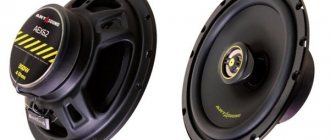
Here we can adjust the low, mid and high frequencies. Marshall
Gives a heavier sound than
a Fender
. Below are the ratings of parts in various variations of these tone blocks
That's probably all. Good luck in your endeavors
Tone block on TL072CP
This article discusses the design of a simple tone block. It is designed to change the sound by adjusting the amplitude-frequency characteristics of the audio signal in the high and low frequencies. The diagram is presented in Fig. 1.
Fig.1. Electrical circuit diagram.
The circuit contains a low-noise operational amplifier TL072CP. It is two-channel, but only one is involved in the circuit. This operational amplifier is housed in a DIP8 package; Figure 2 shows the location of its pins.
Fig.2.
The circuit can use any operational amplifier with similar parameters. Description of the circuit operation. Variable resistor (potentiometer) R4 is designed to regulate the timbre of high frequencies. And R5 is designed to regulate low frequencies. When R4 is in the extreme left position (meaning according to the diagram), the amplitude-frequency response drops in the high-frequency region (Fig. 3). This occurs due to the fact that the R2 C3 circuit, as the signal frequency increases, begins to bypass the lower resistor R3 of the input divider.
Fig.3. Reduced RF. If R4 is in the extreme right position (according to the diagram), then as the frequency increases, circuit C3 R6 bypasses resistor R7, and as a result, negative feedback decreases, raising the frequency response in the high frequency region (Fig. 4).
Fig.4. HF increase. In the middle position of the variable resistor R4, the tone block has almost no effect on the sound.
At different frequencies, the reactance of capacitor C3 will change, causing the processes discussed above. But at frequencies below 1 kHz, the reactance of C3 will be much greater than the resistance of R2 and R6 and adjusting the frequency will have little effect on the sound.
Now let's look at the effect of the variable resistor (potentiometer) R5. When R5 is in the leftmost position (in the diagram), the signal bypasses capacitor C2 and the non-inverting input of the op-amp is not affected. Since in this case the resistance R5 is 100 kOhm, capacitor C4 is shunted, which leads to an increase in negative feedback and a drop in the frequency response in the low frequency region (Fig. 5).
Fig.5. Reduced bass. In the right position of resistor R5, capacitor C4 is now short-circuited. And since C2 is connected in series with one of the resistors of the input divider, it changes its division coefficient, that is, it decreases with decreasing signal frequency. As a consequence of this, the frequency response rises in the low frequency region (Fig. 6).
Fig.6. Increased bass.
The tone block has an input impedance of 47 kOhm. This device can be used with almost any sound amplifier.
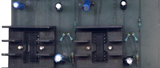
Below are photos of the assembled device.
Nutrition.
Since the basis of the circuit is an operational amplifier, the power supply must be bipolar. Power is supplied to pins 4 and 8 of the microcircuit. The maximum voltage that can be applied to these terminals is +18 -18 Volts relative to the common wire.
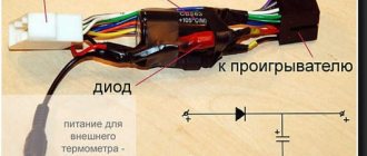
To obtain bipolar voltage from the battery, a simple circuit was used in Fig. 7.
Fig.7.
From a 9 Volt battery, thanks to the divider, we get +4.5 V and -4.5 V at the output. But this circuit does not work very well and is only suitable as a last resort, so it is better to use a more complex circuit in which there will be stabilize the output voltage or use a ready-made power supply.
The maximum permissible supply voltage of the microcircuit is +18 -18 Volts (according to the technical documentation), but I do not recommend applying more than +10 -10 Volts.
Test
To carry out measurements, the output sound signal of the tone control unit was fed to the linear input of the computer (not to the microphone input!). In the Acoustica Mixcraft audio editor, the VST plugin Voxengo Spectrum Analyzer v1.9 was selected. The photo below shows testing taking place (you can evaluate the sound in the video).
Music from the phone was supplied to the input of the tone block (can be from any source: player, computer, etc.)
By changing the resistance of variable resistors R4 and R5, you can achieve a change in sound in the low and high frequency regions. By the way, the timbre block practically does not change the mid frequencies.
This tone block is perfect for acquiring skills in sound conversion.
This article contains a video in which this tone block was tested, you can evaluate its performance.
List of radioelements
| Designation | Type | Denomination | Quantity | Note | Shop | My notepad |
| A1 | Operational amplifier | TL072 | 1 | Search in the Otron store | To notepad | |
| R1, R8 | Resistor | 47 kOhm | 2 | Search in the Otron store | To notepad | |
| R2, R6 | Resistor | 510 Ohm | 2 | Search in the Otron store | To notepad | |
| R3, R7 | Resistor | 2.2 kOhm | 2 | Search in the Otron store | To notepad | |
| R4 | Variable resistor | 20 kOhm | 1 | Search in the Otron store | To notepad | |
| R5 | Variable resistor | 100 kOhm | 1 | Search in the Otron store | To notepad | |
| C1 | Electrolytic capacitor | 4.7 µF | 1 | Search in the Otron store | To notepad | |
| C2, C4 | Capacitor | 0.1 µF | 2 | Search in the Otron store | To notepad | |
| C3 | Capacitor | 0.01 µF | 1 | Search in the Otron store | To notepad | |
| Add all | ||||||
Tags:
- Tone block
- TL072CP
Case manufacturing
The finished tone block circuit must be placed in a shielded case, otherwise the background cannot be avoided.
You can use a regular tin can as a body. Bring the variable resistors out and put handles on them. Be sure to install jack 3.5 connectors at the edges of the can for audio input and output. A tone block or equalizer is a unit that is responsible for cutting off a particular frequency in a low-frequency power amplifier. With its help, you can easily cut low, high or mid frequencies, thus customizing the sound of the amplifier to your taste. The device has found wide application and is being implemented in almost all professional applications. amplifiers can also be supplied separately.
Today we will look at one of these designs, which can work in conjunction with any low-frequency amplifier, including a car one.
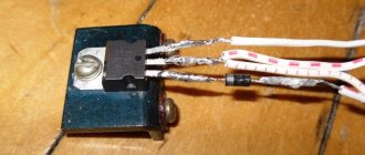
The tone block is active, therefore it has a separate amplifying element, which, in principle, can be anything. An amplifier in such circuits is needed for the final amplification of the signal after processing, since the magnitude of the initial signal is greatly reduced (weakened). The amplifier can be built either on a specialized ULF chip or on an op-amp, but in our circuit, the amplifier is a simple circuit with a single transistor.
This amplifier can be powered by 12 Volts, this makes the circuit universal and allows it to be used in a car. The transistor should be selected with the highest gain factor (HFE). You can use low-power transistors, both composite and conventional. My version uses the BC546 transistor, it is not essential, it can be replaced with any other NPN transistor with the appropriate parameters. My version has controls for bass/treble and volume.
It is recommended to use film capacitors in audio circuits, but the circuit will work perfectly with both conventional and multilayer ceramics. I decided not to make a printed circuit board and limited myself to a prototype circuit board.
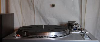
Variable resistors are the most common, their resistance can be from 10 to 68 kOhm, in my version all resistors are 10 kOhm. The design was ultimately placed in a housing from a universal pulse adapter; the size was a good fit.
A low-power mains transformer from a Chinese radio is used as a power source; the output voltage is around 12 Volts; after the rectifier, the voltage is already about 16 Volts.
I drilled holes in the case for input/output, regulators and a power switch, it didn’t turn out very well, but it will work.
The circuit coped with its task very well; it doesn’t even feel like a primitive block is working with zero costs. As for the costs, they are really zero; everything involved can be found in old trash.
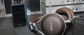
Currently very popular are MP3 players with built-in flash memory, these are very miniature digital personal audio playback devices that work on headphones.
Many of them, in addition to the function of playing audio files recorded in them via a personal computer, have built-in VHF-FM or multi-band digital receivers and a sound recording function from both the built-in microphone and the built-in radio receiver.
Practically, the audio center is the size of a thimble. One problem is that they only work on headphones. For loud playback, an additional external ULF and speaker systems are required.
As an option, you can use active “speakers” for a personal computer, but inexpensive “computer speakers” are usually not familiar with the concept of “sound quality” at all, while higher quality ones cost many times more.
Filter block
If you wish, you can also find a lot of filter circuits, since there are now enough publications on the topic of multi-band amplifiers. To make this task easier and just as an example, I will list here a few possible schemes found in various sources:
- the circuit that I used in this amplifier, since the crossover frequencies turned out to be exactly what the “customer” needed - 500 Hz and 5 kHz and I didn’t have to recalculate anything.
- the second circuit, simpler on an op-amp.
And another possible circuit, using transistors:
As yours already wrote, I chose the first scheme because of the fairly high-quality filtering of the bands and the correspondence of the band separation frequencies to the specified ones. Only at the outputs of each channel (band) simple gain level controls were added (as was done, for example, in the third circuit, using transistors). Regulators can be supplied from 30 to 100 kOhm. Operational amplifiers and transistors in all circuits can be replaced with modern imported ones (taking into account the pinout!) to obtain better circuit parameters. All these circuits do not require any adjustment unless you need to change the crossover frequencies. Unfortunately, I am not able to provide information on the recalculation of these crossover frequencies, since the circuits were looked for as “ready-made” examples and no detailed descriptions were attached to them.
The ability to disable filtering on the MF and HF channels has been added to the filter block circuit (the first of three circuits). For this purpose, two push-button switches of the P2K type were installed, with the help of which you can simply close the connection points of the filter inputs - R10C9 with their corresponding outputs - “HF output” and “MF output”. In this case, the full audio signal is transmitted through these channels.
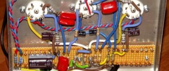
ULF power supply
Two transformers with blocks of rectifiers and filters were used as a power supply according to the usual, standard scheme. To power the low-frequency band channels (left and right channels) - a 250-watt transformer, a rectifier based on diode assemblies such as MBR2560 or similar, and 40,000 microfarad x 50 volt capacitors in each power arm. For the midrange and high-frequency channels - a 350-watt transformer (taken from a burnt-out Yamaha receiver), a rectifier - a TS6P06G diode assembly and a filter - two capacitors of 25,000 uF x 63 volts for each power arm. All electrolytic filter capacitors are shunted by film capacitors with a capacity of 1 microfarad x 63 volts.
In general, the power supply can have one transformer, of course, but with its corresponding power. The power of the amplifier as a whole in this case is determined solely by the capabilities of the power source. All preamplifiers (timbre block, filters) are also powered from one of these transformers (possibly from any of them), but through an additional bipolar stabilizer unit assembled on a KREN (or imported) MS or using any of the standard transistor circuits.
Tone block circuit
The circuit contains only passive elements (capacitors, resistors).
Two variable resistors are used to adjust the level of high and low frequencies. It is advisable to use film capacitors, however, if you don’t have any at hand, ceramic ones will also do. For each channel you need to assemble one such circuit, and in order for the adjustment to be the same in both channels, use dual variable resistors. The printed circuit board posted in this article already contains this circuit in duplicate, i.e. has input for both left and right channels. Download the board: (downloads: 638)
Power amplifiers
From the output of each filter channel, HF-MF-LF signals are fed to the inputs of power amplifiers, which can also be assembled using any of the known circuits, depending on the required power of the entire amplifier. I made the UMZCH according to the long-known scheme from the magazine “Radio”, No. 3, 1991, p. 51. Here I provide a link to the “original source”, since there are many opinions and disputes regarding this scheme regarding its “quality”. The fact is that at first glance this is a class “B” amplifier circuit with the inevitable presence of “step” distortion, but this is not so. The circuit uses current control of the transistors of the output stage, which allows you to get rid of these shortcomings during normal, standard switching on. At the same time, the circuit is very simple, is not critical to the parts used, and even the transistors do not require special preliminary selection of parameters. In addition, the circuit is convenient in that powerful output transistors can be placed on one heat sink in pairs without insulating spacers, since the collector terminals are connected at the point " output”, which greatly simplifies the installation of the amplifier:
When setting up, it is only IMPORTANT to select the correct operating modes of the transistors of the pre-final stage (by selecting resistors R7R8) - at the bases of these transistors in the “rest” mode and without load at the output (dynamics) there should be a voltage in the range of 0.4-0.6 volts. The supply voltage for such amplifiers (there should be 6 of them, accordingly) was raised to 32 volts with the replacement of the output transistors with 2SA1943 and 2SC5200, the resistance of resistors R10R12 should also be increased to 1.5 kOhm (to “make life easier” for the zener diodes in the circuit power supply of input op-amps). The op-amps were also replaced with BA4558, in which case the “zero setting” circuit (outputs 2 and 6 in the diagram) is no longer needed and, accordingly, the pinout changes when soldering the microcircuit. As a result, when tested, each amplifier using this circuit produced power up to 150 watts (short-term) with a completely adequate degree of heating of the radiator.
Structural scheme
The figure below shows the circuit diagram of channel 1:
As can be seen from the diagram, the amplifier has three inputs, one of which provides a simple possibility of adding a preamplifier-corrector for a vinyl player (if necessary), an input switch, a pre-amplifier-timbre lock (also three-band, with adjustable HF/MF/LF levels), volume control, filter block for three bands with adjustment of the gain level of each band with the ability to disable filtering and a power supply for high-power final amplifiers (unstabilized) and a stabilizer for the “low-current” part (preliminary amplification stages).
Homemade amplifier design
This was, perhaps, the most difficult moment in manufacturing, since there was no suitable ready-made housing and I had to come up with possible options :-)) In order not to sculpt a bunch of separate radiators, I decided to use a radiator housing from a car 4-channel amplifier, quite large in size, something like this:
All the “internals” were, naturally, removed and the layout turned out something like this (unfortunately, I didn’t take a corresponding photo):
— as you can see, six terminal UMZCH boards and a pre-amplifier-timbre block board were installed in this radiator cover. The filter block board no longer fit, so it was secured to a structure made from an aluminum corner that was then added (it can be seen in the pictures). Also, transformers, rectifiers and power supply filters were installed in this “frame”.
The view (from the front) with all the switches and controls turned out like this:
Rear view, with speaker output terminals and fuse box (since no electronic protection circuits were made due to lack of space in the design and in order not to complicate the circuit):
Subsequently, the frame from the corner is, of course, supposed to be covered with decorative panels to give the product a more “marketable” appearance, but this will be done by the “customer” himself, according to his personal taste. But in general, in terms of sound quality and power, the design turned out to be quite decent. Author of the material: Andrey Baryshev (specially for the site site
).
Many modern audio systems, be it a stereo system, a home theater, or even a portable speaker for a telephone, have an equalizer, or, in other words, a tone block. With its help, you can adjust the frequency response of the signal, i.e. change the amount of high or low frequencies in the signal. There are active tone blocks, built, most often, on microcircuits. They require power, but do not weaken the signal level. Another type of tone blocks are passive; they slightly weaken the overall signal level, but do not require power and do not introduce any additional distortion into the signal. That is why in high-quality sound equipment, passive tone blocks are most often used. In this article we will look at how to make a simple 2-way tone block. It can be combined with a homemade amplifier, or used as a separate device.
Design and setup.
Placement of amplifier elements on the board:
Click to enlarge
During assembly, the resistors are soldered first, and then the remaining components. Jumper JP1 is designed to select the optimal ground connection for the vinyl corrector (there are similar jumpers on MC / MD boards). Don't forget to connect them. The connection location is selected experimentally after assembling the structure in the housing.
Photo of the assembled board:
Click to enlarge
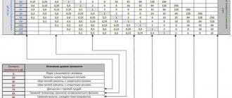
This block of settings does not require. Frequency characteristics of the amplifier and tone control:
Click to enlarge