Nowadays, most electronic devices are powered using lead-acid batteries. In this article, we will look at how to recharge such batteries using a simple Arduino circuit that can be assembled at home - a great chance to save on buying a charger.
First, let's try to understand the basic principles of how lead-acid batteries work so that we can design our charger in the most efficient way possible. Most lead acid batteries currently sold are 12V. The ampere hours (Ah) of each battery may vary depending on the required battery capacity, for example a 7Ah battery will be capable of delivering 1Amp of current for 7 hours (1 Ampere * 7 hours = 7 A*h).
The recommended charging current for lead-acid batteries is 1/10 of their capacity (in Amp-hours). That is, for a battery with a capacity of 7 Ah, the recommended charge current will be 0.7 Amperes. Higher charging current may harm the battery and reduce its service life. Taking this factor into account, we will design our home charger capable of providing alternating voltage and alternating current. The charging current will be adjusted based on the battery capacity value.
The lead-acid battery charger we create can also be used to charge your mobile phones by appropriately adjusting the supplied current and voltage using a potentiometer. That is, our device is a source of regulated direct current, which operates from an alternating current network. Also, for a better understanding of the material in this article, you can read the project of a 0-24V 3A power supply voltage on Arduino and LM338 recently reviewed on our website.
Required Components
- Transformer 12V 1A.
- LM317 chip (2 pcs.) (buy on AliExpress).
- Diode bridge W005.
- Contact block (2 pcs.).
- Capacitors 1000 uF (buy on AliExpress) and 1 uF (buy on AliExpress).
- Capacitors 0.1 uF (5 pcs.) (buy on AliExpress).
- Resistor 1 kOhm (5 pcs.) (buy on AliExpress).
- Diodes Nn007 (3 pcs.).
- Operational amplifier LM358 (buy on AliExpress).
- Shunt resistance (conductor) 0.05 Ohm (buy on AliExpress).
- Arduino Nano board (optional) (buy on AliExpress).
- LCD display 16x2 (optional) (buy on AliExpress).
Analogs LM317
What to do if it is not possible to use LM317? You can use its analogues. The twin brothers of this component are UPC317, GL317, ECG1900 and SG317. The domestic analogue is KP142EH12A, and there is also a KP142EN12 with a fixed voltage.
If the LM317 is not enough power for your project, then you can use more powerful options:
- LM350AT and LM350T – maximum output current 3A and power 25W
- LM350K – current 3 A and power 30 W
- LM338T and LM338K – current 5 A
All these microcircuits have the same pins, so the circuits do not have to be changed in any way.
Circuit operation
The charger circuit without Arduino board and LCD display is shown in the following figure.
The main purpose of our 12V power supply is to control the voltage and current supplied to the lead-acid battery in order to charge it at its maximum comfort level. For this purpose, the circuit uses two LM317 microcircuits - one to control the voltage value (U3), and the second (U1) to limit the current. We would also strongly recommend that you study the datasheet for the LM317 chip, as it may be useful to you not only for this project, but also for other similar projects in which this chip is used as a voltage regulator.
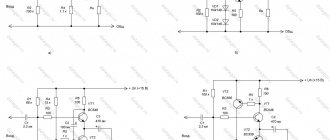
A simple voltage regulator circuit taken from the LM317 datasheet is shown in the following figure.
In this circuit, the value of the output voltage is adjusted using the values of resistances R1 and R2, in our project we do this by changing the resistance of resistor R2. The formula for calculating the output voltage value is as follows:
Vout = 1.25 (1+R2/R1).
Using this formula, in our project we chose a resistance value of 1K (R8) and used a 10K potentiometer (RV2).
The current limit circuit, taken from the LM317 datasheet, is shown in the following figure.
This is a simple circuit that can be used to limit the current value in our circuit based on the resistance value of R1. The formula for calculating the output current value is as follows:
Iout= 1.2/R1.
Based on this formula, we chose the resistance value RV1 = 100 Ohm in our circuit.
That is, to control the values of the output voltage and current, we used two potentiometers in our circuit - RV1 and RV2. Voltage is supplied to the LM317 microcircuit from the output of the diode bridge, and to the diode bridge - from the output of the transformer through connector P1. The transformer must be 12 V and 1 A. The presented circuit is sufficient to perform the assigned function - to provide the specified current and voltage at the output of the circuit. But it can be improved with the help of an LCD display, on the screen of which you can clearly control the specified parameters.
↑ Current charging mode
A friend called me and said that he needed a charger for a screwdriver at his dacha.
According to him, there are 10 batteries in the battery with a capacity of 1400 mAh. This means that you need to charge the 12 Volt battery. The batteries are nickel-cadmium, three charging modes are possible for them: “A” - slow, with a current of 0.1 of the capacity, charging time 14-16 hours; “B” - ultra-fast, current from 1 to 4 capacities, time about 1 hour; “B” - accelerated, current is approximately 0.25 of the capacity, charging time is 4-6 hours. In my opinion, option “A” is too slow until the battery charges, or the desire to work disappears, or it’s time to leave.
Option “B” is risky, there is a high probability of explosion or failure of the battery, to prevent this you need to control the temperature of each element, the circuit must be complex, preferably on a microcontroller, you will have to write and debug a program for it, not all batteries can withstand such a regime , especially sealed ones.
Mode “B” remains - in the evening the battery is charged, in the morning the batteries are fully charged, the charge is full, the likelihood of problems is minimal.
The analysis of industrial circuits surprised me. They usually do not have current stabilization; the limitation occurs due to the resistance of the secondary winding of the supply transformer. This means that if the mains voltage deviates, either there will be no full charging, or the current will increase significantly. Our charging current will be stabilized
at a given level, which completely eliminates these disadvantages.
Displaying Voltage and Current Values on LCD Using Arduino
We can display the current values of voltage and current at the output of our circuit using an Arduino Nano board and a 16x2 LCD display.
Since the Arduino Nano board operates with voltages of no more than 5 V, in order not to burn it with a voltage of 12 V, we will use a voltage divider, the circuit of which is shown in the following figure. Also, issues of controlling the voltage value at the output of the circuit using the Arduino board can be studied in the article about the power supply voltage 0-24V 3A on Arduino and LM338.
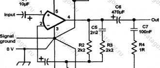
To measure the current value, we used a shunt resistor R4 to create a voltage drop across the resistor as shown in the following diagram. After this, we can easily determine the current value using the well-known Ohm's law - I=V/R.
We chose the shunt resistance value to be 0.05 Ohm, so the maximum current that can be passed through our circuit will be 1.2 A, which corresponds to the transformer parameters we selected. The power dissipated by the resistor can be determined using the well-known expression P=I^2/R. In our case, we get P=(1.2*1.2*0.05) => 0.07, which is less than a quarter of a watt. If the value of the shunt resistance changes, the dissipated power will need to be recalculated.
Now that we can calculate the voltage drop across R4, we can calculate the current through our circuit using Arduino. But this voltage drop is too small to be measured using Arduino. Therefore, in our circuit we have used an operational amplifier LM358 as shown in the above figure. The output signal of this op amp is fed to our Arduino board through RC circuit to measure the current value and display it on the LCD display.
Next, you can use some kind of simulator (recommended) to check the functionality of the circuit before assembling it in hardware. In this case, we used the Proteus 8 simulator to test the circuit as shown in the following figure. You can download the finished file of our circuit for this simulator using the following link.
↑ Shutdown criterion
So, the current mode has been selected, the next and most difficult stage is the selection of the charging shutdown criterion.
Typically used: • shutdown by timer, • upon reaching a threshold voltage, • by a tiny voltage drop when fully charged, • by battery temperature. The problem is that the implementation is complex in some cases and unreliable in others. An acceptable option is threshold voltage
, but if at least one element is bad, the voltage will never reach the threshold level. Therefore, I recommend checking the voltage of a specific battery when charging for the first time. The literature says that the full charge voltage per cell is 1.45-1.48 V.
Creating a printed circuit board for our device
This article is a translation from this article on an English-language site and I did not translate the section on creating a printed circuit board because the approaches used by the authors of the original article to create a printed circuit board may differ radically from the approaches you use. Therefore, if you want to implement the 12 V charger discussed in this article on a printed circuit board, you can do it in any way convenient for you (to which you are accustomed). The authors of the original article ended up with a device of the following type:
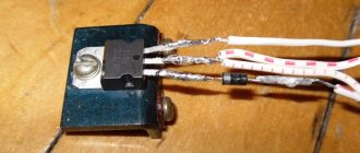
How to test LM317?
Unlike transistors, this microcircuit cannot be checked with a multimeter. This method does not in any way guarantee correct operation due to the large number of internal elements not connected to the terminals. Therefore, if one of them fails, then checking it with a multimeter will be problematic. The easiest way to test the operation of the LM317 is to create a simple stand on a breadboard, and it can be powered only by a battery.
This way, you can quickly verify that an item is in full working order, even if you need to check several pieces.
Charger testing
The Arduino board and LCD are not required elements for our circuit - they are only used for control purposes, so you can temporarily mount them on the circuit using special pads so that you can easily remove them later and use them in other projects.
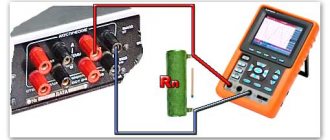
To test the device, remove the Arduino board from it and connect the circuit to a transformer. After this, adjust the output voltage to the required level using potentiometer RV2. Check the output voltage of the circuit using a multimeter and connect it to the battery as shown in the following figure. Now our device is ready for use.
Before connecting the Arduino board to our circuit, make sure that the voltage on the pin to which we will connect it does not exceed 5 V, otherwise we may damage the Arduino board. Use the program text below to upload it to the Arduino board. This program is designed to display current and voltage values on the LCD screen. This entire process is shown in more detail in the video at the end of the article.
This device can also be used to charge cell phones, but for this you will need to clarify what voltage and current values are required to charge your cell phone. You will also need to connect a USB cable to the circuit.
Types of LM317
The microcircuit is sold in several housing options, depending on the need for size, load and connection, as well as the type of circuit installation - everyone can choose the option that suits them best.
The most popular is the LM317T in a TO-220 1.5 Ampere package. This is considered a universal option, as it can be used in surface-mounted as well as surface-mounted applications. A radiator in such a case allows you to remove excess heat and experience more severe loads than its counterparts, and if necessary, it can be attached to a larger radiator.