Tube amplifier circuitry is deceptively simple.
Each stage consists of only a few components: the lamp itself, two or three or four resistors and two or three capacitors. The output stage of a tube amplifier can be single-ended (SE) or push-pull (PP) and usually contains a transformer. In this publication, we will look at the operating features of single-ended and push-pull output stages, learn about the operating modes of tubes, and discuss the use of powerful triodes in single-ended output stages of tube amplifiers. To lay the foundation for understanding the processes occurring in the output stages of tube amplifiers, let us turn to the textbook diagram of a school radio unit, which went through five reprints in the book “Young Radio Amateur” by V. Borisov. The design was first published in the first edition of 1951, in the third edition of 1959, in the chapter devoted to improving the design, the conversion of a single-ended (SE) output stage into a push-pull (PP) was described, in the fourth (1966) and fifth (1972) editions into variants Finger lamps were introduced into the design.
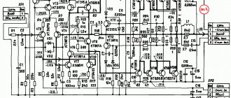
▍ Circuit with single-ended output stage
Let's analyze the circuit of a school radio node; consider canonical 6P3S as output lamps. We will take diagrams, descriptions and graphs from the fifth edition, as they are the most tested by several generations of radio amateurs.
The output stage is assembled according to an automatic bias circuit. The voltage at pin 3 of lamp L3 (anode) is +270 V, the voltage at pin 8 (cathode) is +14.5 V. These voltages are measured relative to the common wire. Regarding the cathode, we obtain the anode voltage UA = 270 – 14.5 = +255 V, and the bias voltage on the lamp control grid UC = 0 – 14.5 = –14.5 V. The value of the cathode resistor R15 = 200 Ohm. The current through the cathode resistor is 14.5 / 200 = 72.5 mA. Bypass capacitor C12 serves to prevent negative AC feedback.
Let's compare with the passport data of the 6P3S lamp. At a voltage on the anode and screen grid of +250 V, the anode current of the 6P3S lamp should be within (72 ± 14) mA, and the screen grid current should not exceed 8 mA. The recommended value of the bias voltage on the control grid is minus 14 V. With anode current IA = 72 mA and screen grid current IE = 8 mA, the value of the cathode resistor should be UC / (IA + IE) = 14 / 0.08 = 175 Ohm.
The operating mode of the output stage lamp, in principle, corresponds to that specified in the passport. The declared output power of the amplifier is 5 W, which also corresponds to the passport characteristics of the 6P3S. The output stage circuit is a canonical single-ended “class A” pentode with automatic bias.
▍ Circuit with push-pull output stage
A power of 5 W may not be enough for a radio amplifier. It is proposed to increase the output power by replacing the single-cycle output stage (SE) with a push-pull (PP). To do this, the output stage is excluded from the original circuit, and one of the circuits given below is connected instead:
The circuit has become much more complicated: instead of one stage on one lamp, there are now two stages on three lamps.
A phase inverter circuit is assembled on lamp L1, converting the input analog signal into two antiphase output signals. A signal with a phase of 0° is supplied to the “upper arm” of the output push-pull stage, and a signal with a phase of 180° is supplied to the “lower arm”.
The output stage now has two 6P3S lamps. The stated output power of the amplifier is 15-20 W. In theory, adding a second 5 W lamp to the output stage would increase the amplifier power by these 5 W, i.e. twice. We'll look into why the output power has increased three to four times later.
The design of the output transformer has changed: the cross-section of the magnetic core has increased to increase the overall power, and the primary winding has a tap from the middle.
The anodes of the output lamps are connected to the outer terminals of the primary winding, the anode voltage source is connected to the middle point. The halves of the primary winding are connected in such a way that antiphase currents in the halves of the primary winding cause currents in the same direction in the secondary winding of the output transformer. Accordingly, the common-mode anode currents in the secondary winding are subtracted from each other.
The value of the cathode resistor in the diagram is 220 Ohms. In terms of direct current, the lamps in a push-pull cascade are connected in parallel; accordingly, a significantly larger current flows through this resistor than would flow through a cathode resistor of the same rating in a single-cycle circuit, therefore, the bias voltage module on the control grids of the push-pull cascade under consideration will be greater.
Tube amplifiers. Oscilloscope distortion assessment
Evaluating amplifier distortion using a square wave generator and oscilloscope. To approximate the quality of operation of a low frequency amplifier (LF), it is enough to use a simple square pulse generator (RPG) and an oscilloscope. A GPI is connected to the input of the ULF under test, producing a signal with a frequency of 1 kHz and an amplitude equal to half the rated input voltage of the ULF. The amplifier output is loaded with a resistive resistance Rн equal to the rated load. The power of the resistor Rн is selected greater than the output power of the amplifier. An oscilloscope is connected parallel to the load as in the figure.
A comparative assessment of the identity of two stereo channels in the presence of a dual-beam oscilloscope is very useful. By simultaneously observing two output signals, one can judge the accuracy of the dual potentiometers, the identity of the filters, and also compare them with the reference signal.
A rectangular pulse contains a spectrum of frequency components: the fundamental frequency (coincides with the pulse repetition frequency) and a number of frequency components, well expressed at least up to the tenth harmonic. If you apply rectangular pulses with a repetition frequency of 50 Hz to the amplifier input (usually for these purposes they use not rectangular pulses of one polarity, but bipolar rectangular pulses (the so-called “meander”), this will be equivalent to applying a set of frequencies from 50 to 500 to the amplifier input... 1000 Hz. If pulses are applied with a repetition rate of 1 kHz, the range of test frequencies will expand to 10...15 kHz. By connecting an oscilloscope to the output of the amplifier, on its screen we will receive an image of the test pulse, which will be undistorted only if the frequency components of the pulse pass through the amplifier undistorted, i.e. they will not experience either frequency (amplitude) or phase distortion.If the pulse at the output of the amplifier has the same shape as at the input, then everything is in order (the comparison is made using a double-beam oscilloscope or a single-beam, but with electronic switch).If the shape of the output pulse is distorted, then the nature of the distortion can determine the malfunction of the amplifier. The sensitivity of this method even to minor distortions is quite high.
Pulse oscillograms are deciphered as follows: distortions of the vertices of a rectangular pulse (curvature and slope) are caused by low-frequency distortions of the signal in the amplifier circuits, and distortions of the pulse front (rounding and stretching) are caused by high-frequency ones, since different sections of the amplifier for pulses are differentiating and integrating circuits. In the figure below, capacitor C is a transition capacitor, and R is the total resistance of the input circuit of the subsequent amplifier stage. How does a square pulse pass through such an RC circuit? At the moment the pulse front appears, capacitor C begins to charge, but this cannot happen instantly, since charging the capacitor means the existence of an electric field between its plates, which, having energy, cannot change instantly. Therefore, at the first moment after the front appears, the voltage Uс on the capacitor is zero and the charging current depends only on the resistance R: Iз = Ui/R. Consequently, at this moment a voltage surge Ur=IзR=(Uи/R)R=Ull will occur at resistance R. Low frequency and high frequency distortion are shown in the figure below
However, the very next moment a certain voltage Uc will appear on capacitor C and the discharge current will be determined by the expression Iз = Ui-Uc/R, i.e. it will begin to decrease. Therefore, the voltage Ur across resistance R will also begin to decrease, and this will cause distortion (peak sweetening) of the pulse at the output of the circuit, which will be greater, the smaller the capacitance of capacitor C (the smaller the capacitance, the faster charging occurs, the more intense the charging current decreases, the more steeper decline in the peak of the impulse). This is determined not only by the capacitance C, but also by the resistance R, therefore the ability of the circuit to pass a pulse voltage through itself is characterized by the parameter x=RC, called the time constant. It can be proven that in time t=3RC=3x the capacitor will charge to approximately 0.95 max. source voltage.
It must be remembered that the pulse undergoes distortions, which will be less, the longer the time constant of the circuit. Indeed, if the duration of the pulse Ti is much less than three time constants of the circuit (Ti <3t), then during the pulse the voltage Uc on the capacitor does not have time to change significantly, which means that the top of the pulse will hardly be distorted. But if the time constant is commensurate with the pulse duration or less than it, then the RC circuit significantly distorts the top of the pulse or even turns it into two pointed pulses (differentiates it). Strictly speaking, any RC circuit, the output voltage of which is removed from a resistor, is differentiating, but if for a given pulse the relation Ti < 3m is maintained, then such a circuit should be considered a transition circuit.
Below are typical cases of signal distortion when passing through the ULF.
| 1. The amplifier is working properly and it transmits the signal evenly over a fairly wide frequency band | 2. Weakening the amplification of low-frequency signals with a linear amplifier characteristic. The slope is caused by a roll-off in the region below 20 Hz or the presence of a low-pass filter |
| 3. Increase in gain at low frequencies. The time constant of interstage connections is small (usually the capacitance of the transition capacitors is small) | 4. High frequency attenuation (approximately -6 dB at 3 kHz, -15 dB at 10 kHz) |
| 5. Increase in gain at high frequencies (6 dB at 10 kHz) | 6.Low-frequency attenuation (-15 dB at 50 Hz) |
| 7. The amplifier has resonating circuits and parasitic oscillations, the frequency of which is higher than the upper limit of the frequency response | 8. Self-exciting amplifier, under load |
| 9. Half-wave asymmetry means large distortions, a possible reason is inaccurate selection of the transmission coefficient of the output elements | 10. Increase in gain at low frequencies is not standardized |
| 11. Gain boost at mid frequencies is not standardized | 12. The gain drop at mid frequencies is not normalized (dip at the top) |
| 13. Gain reduction in a narrow frequency range is not standardized |
The pictures shown are rather crooked, but the characteristic features of signal distortion can be understood from them. This is useful for simple diagnostics of a newly manufactured device. Most often, the initial tuning is associated precisely with the elimination of obvious jambs in the operation of the amplifier. As a rule, this is enough to satisfy the sound quality requirements of 90% of TV viewers. The quality of the tube sound after correcting the errors will be quite decent.
Of course, for a more detailed examination of a hand-made lamp device and its careful adjustment, more modern measuring instruments are needed. The use of computer tools and software built in the Spectrolab shell seems very promising. In addition to high accuracy, this approach makes it easy to save measurement results. How to use these results is a matter of technology. Of course, advanced digital tools do not cancel the measurement results of analog devices. In many cases, an analog meter is clearer and often more reliable. But no one can cancel progress, so digital meters and technologies rule.
Evgeny Bortnik, Krasnoyarsk, Russia, May 2016
▍ Operating modes of the amplifier stage on lamps
The operating mode of the amplifier stage on tubes is determined by the bias voltage on the control grid. It is clearer and easier to demonstrate this on the graph of the anode-grid characteristics of the triode:
The segment between points “b” and “c” is of greatest interest on the curve.
This is a linear section of the anode-grid characteristic at a negative voltage on the control grid. The cross on the curve marks the middle of this section, i.e. “operating point” of the cascade when operating in mode A. If you set the bias voltage UC on the triode grid to minus 4 V, the quiescent current IA will be 4.5 mA. A cascade with such a bias will be able to amplify an input signal with an amplitude of up to 4 V without distortion. When a signal with a larger amplitude is applied to the input, the voltage on the grid may go beyond the linear section, which will lead to nonlinear distortion.
It should be noted that when the grid potential is positive relative to the cathode, a so-called “grid current” IC, which is equivalent to turning on a diode between the control grid and the cathode. This effect has found wide application in radio engineering, but when amplifying sound it is undesirable, because introduces noticeable distortion into the signal.
Operation in mode A, when the voltage on the grid does not go beyond the “b-c” section, provides minimal distortion, but is energy inefficient: the lamp in this mode operates without a “cutoff”, current always flows through it, and most of the energy is spent on heating the anode. The efficiency of class A amplifiers does not exceed 25-30%.
We begin to shift the “working point” towards point “b”. At some point in time, a “cutoff” begins (no current flows through the lamp) of part of the negative half-wave of the input signal. The amplifier enters AB mode. The efficiency in this mode is 50-60%.
A single-ended (SE) amplifier, when switching to AB mode, begins to introduce noticeable distortion into the signal. The distortion introduced into the signal by a push-pull (PP) amplifier in AB mode is much less noticeable.
The distortions introduced into the signal by a push-pull amplifier become noticeable when the “operating point” is shifted beyond point “b” on the graph. At point “a” the amplifier goes into mode B with a “cutoff” of exactly half of the sine wave and an efficiency of 80% or higher.
When the “operating point” shifts to the left of point “a” on the graph, the amplifier goes into mode C with a “cutoff” of more than half of the sine wave, when no current flows through the lamp for most of the input signal period, and an efficiency of 90% or higher.
In audio amplifiers, tubes operate either in “pure class A” (regardless of the switching circuit), or in AB mode in push-pull circuits.
To understand why adding a lamp to a push-pull output stage does not double, but triples or even quadruples the output power, remember that the output transformer modulo sums the antiphase anode currents of the output stage lamps, which ideally leads to a doubling of the output current amplitude, which and ultimately gives a gain of 4 times in power even when the output stage is operating in mode A.
When push-pull cascades operate in AB mode, there is another feature. Let's look at it using the example of the operation of a push-pull output stage with the characteristics of the lamps as in the graph above. To do this, we enter the cascade into AB mode, setting the bias voltage to minus 8 V. The cascade can now amplify the input signal with an amplitude of up to 8 V without distortion, i.e. in this mode, you can apply a “drive” voltage to the output stage that is 8 / 4 = 2 times greater, which, other things being equal, again leads to an increase in output power by 4 times.
Setting up lamp UMZCH
Due to the increased popularity of tube sound, many have rushed to build tube amplifiers. But, although LUs are less demanding in terms of modes and element base, after assembly they still need to be configured, taking into account some features.
Attention! Voltages in anode circuits can be life-threatening. De-energize the device before intervention, discharge the smoothing capacitors, perform work using tools with reliable electrical insulation and, if it is necessary to work under voltage, ensure the presence of persons capable of providing first aid to you in case of electric shock.
As with any other control system, testing and adjustment should be carried out from the “tail” to the “head”. Let's start with a 1-cycle circuit (Fig. 1).
Surely everyone collected something similar at the dawn of their hobby.
Setting up the output stage.
So, let's start with the output stage. We remove C7 from the circuit and consider the cascade on VL2.
1. A hum is heard at a frequency of 50Hz.
1-1. Problem with BP.
The capacitance of the capacitors in the smoothing filter or the inductance of the inductor is low. Typically, electrolytic capacitors are used, which lose capacity over time - “dry out”. You should start with the capacitor closest to the rectifier. It is also possible that the rectifier circuit itself does not match the current consumption. I recommend bridge rectifiers - their capacitors are almost 2 times smaller than in other circuits.
1-2. There is guidance along the grid chain.
You can reduce R9 a little, but the smaller the change, the better, since in such a circuit this will lead to a decrease in the input impedance of the cascade and a deterioration in the frequency response.
If possible, it is better to shield all signal lines. In particular from C7 to the VL2 control grid.
Another possible reason could be excessive resistance R10. But it should be selected with extreme caution, since its selection affects the DC mode of the stage and can lead to an increase in nonlinear distortions.
1-3. The capacity of C8 is small. Needs to be replaced or matched. However, be aware that excess capacitance will result in RF losses.
2. Noise is heard.
Here you should determine the tone of the noise “brown (pink)” or “white”. I have attached samples in the archive.
2-1. In the case of low-pitched noise, you need to check the capacitors in the anode and cathode circuits (as well as other reactive elements, if any). This is the so-called local feedbacks (hereinafter referred to as OS. OOS - negative feedback - antiphase signal in relation to the working signal, POS - positive feedback - common-mode signal), which limit the gain, but at the same time suppress noise, nonlinear distortions and self-excitation. They may not correspond to the declared parameters, be missing or have a missing contact (poorly soldered). It is also possible that the developer of the circuit itself made a mistake (usually such elements are marked “*”, i.e. the element needs to be selected).
2-2. High-pitched (“white”) noise appears as a result of a faulty lamp or the same missing contact. Don't rush to change the lamp right away. Most likely this is an oxidized socket. It is better to wash it with something neutral or replace it. Processing with abrasive tools can lead to the opposite results. The physics of this process is quite clear: when there is loose contact between the pins and the socket, spark discharges occur, and the ozone that is formed in this case oxidizes both surfaces even more actively. You can determine the source of the problem by clicking on the lamp with your finger. A rustling sound means a malfunction of the socket, a ringing sound means a malfunction of the lamp. If this method does not work, temporarily replace the lamp and try again.
2-3. Also, the cause of any noise may be excessive resistance of the anode-cathode circuit. Start selecting R10 (within small limits to begin with, otherwise you will damage the lamp and transformer). If the selection of this resistor does not give tangible results, I do not envy you - the problem is in the DC anode circuit mode. This means that the transformer does not meet the required parameters of the cascade. You will have to either select another transformer or rewind the existing one. God forbid you survive this!
3. Nonlinear distortions. This is a type of distortion that can be observed as geometric changes in the waveform on an oscillogram. By ear, they are determined by different signs: at low frequencies, wheezing increases noticeably, at high frequencies, “wheezing” becomes “hissing.” As stated, such distortions are a consequence of overload - excessive gain, excessive input signal level, shift of the operating point, etc. Let's look at the most typical sources.
3-1. Lack/excess of anode voltage. All this leads to a shift in the operating point, therefore, some half-waves are suppressed by the DC lamp mode. The situation is similar to steps 2-3. You should work in the same way, but before that you should check the U. supply voltage in silent mode and in the presence of a signal (if reducing the input signal level allows you to remove distortion, then the output stage is working). Actually, in this case, it is inappropriate to talk about the device as a class “A” amplifier.
3-2. Reducing the intensity. The current-voltage characteristic of the lamp, in this case, is also far from ideal. This can be easily verified by sending a signal to a poorly heated lamp. Actually, this is not such a serious problem. It all comes down to the readiness time of the U. This can also happen with a transistor U., only there the time depends on the capacity (charging time) of the smoothing capacitors.
3-3. Excess input voltage. You can put a resistor between the coupling capacitor C7 and the control grid VL2. The additional resistor and R9 form a divider that will lower the signal. This will change the frequency response, but the rise to low frequencies can be solved by selecting C7 (decreasing). By the way, R9 also has a certain influence on the DC mode, so by selecting it you can also achieve the desired results.
Setting up preliminary stages. Now let's return C7 to its place and remove C2. Thus, a ready-made U is obtained, covered by the OS. By and large, the 2nd stage is needed only to compensate for losses in fine correction circuits. Those. with an input signal voltage of 1.5-2V, the 1st stage can be completely eliminated. In fairness, it should be noted that each stage inevitably introduces distortion and noise, and at the output it all adds up. In reality, everyone decides for themselves how many stages are needed to provide the required gain. What was said above is also true for triodes. Here the task is even somewhat simplified, since the anode is loaded not on a transformer, but on a regular active load - a resistor, part of which, if necessary, can be replaced with a tuning one. I would not recommend getting carried away with this, since variable resistors can also be a source of noise (including white noise, which many, due to inexperience, attribute to the sins of the lamp). So, we will not discuss the mode of the VL1-2 cascade and move on to the control unit as a whole. As can be seen from the diagram, a very important circuit was included in the work - the loop of the general environmental protection system. As we know, the OS phase depends on which output of the secondary winding the loop is connected to. Since the difference is 180 degrees, the OS can become positive. If, when turned on, the noise or background sharply increases, then the U has become a generator. Before working magic on the triode, transfer the OS circuit to another terminal of the secondary winding (the remaining one, accordingly, switch to common). The loop consists of R8R11R12. The resistor in the cathode circuit VL1-2 is the load of this divider. As a rule, the feedback does not have a significant effect on the cathode DC mode, but for this the condition R11+R12>>R8 must be met. With the help of OOS, you can significantly reduce noise and distortion, but without fanaticism, since this effect is achieved by reducing the gain until the signal is completely blocked.
Now let's look at 2-cycle amplifiers. In fact, the preamplifier in such circuits is no different, but instead of an output stage there is a phase inverter, which splits the signal into half-waves and amplifies each separately. It is quite clear that the DC mode in such cascades is shifted to “-”, which makes it possible to maximize the positive half-wave and ignore the negative one, which is shifted by 180 degrees by the bass reflex and is amplified by the second arm. In circuitry this is implemented in 2 ways. Figure 2 shows a method where the triode is simultaneously an inverter, like preliminary stages, and a cathode follower.
Such a cascade, despite its apparent simplicity, is quite complicated to set up. First of all, this is due to the fact that the inverter and repeater have different output resistances and, accordingly, different load capacities. To drive such a cascade into mode, it is necessary not only to achieve its symmetry relative to the power poles, but also to carefully select the constant voltage on the grid (respectively, the anode voltage of the left triode L2), so that the amplitudes of the separated signals are equal in magnitude (reminiscent of the operation of a Maxwell pendulum), but The bass reflex itself did not leave linear mode. Judge for yourself the consequences of FI imbalance. My subjective opinion is that God bless it, with simplicity, for the sake of getting rid of such difficulties and an extra lamp, it’s not a pity. Another option is when the FI consists of 2 conventional cascades with a common cathode (Fig. 3).
The left triode L1 rotates the phase by 180 degrees. and transmits to the second triode and the lower anti-phase pentode. The right triode rotates the phase by another 180 degrees (returns to its original state) and transmits it to the common-mode pentode. In addition to the described operations with single-ended cascades, we only have to select the input divider of the right triode so that the amplitudes of the anode signals are equal.
As far as lamps go, that's probably it. In the next article we will consider semiconductor UMZCH. We will discuss questions on the forum.
Sincerely, Pavel A. Ulitin. Chistopol (Tatarstan).
The article uses illustrations from R. Svoren’s book “Amplifiers and Radio Units” (1965)
Attached files:
- noise.rar (188 KB)
▍ Features of the operation of push-pull circuits
The use of push-pull circuits with AB operating mode provides a significant increase in output power while increasing efficiency.
Push-pull circuits have a lower nonlinear distortion coefficient compared to single-cycle ones due to better suppression of even-numbered harmonics. The quality of the output signal of push-pull circuits with AB operating mode is ensured by symmetry: the output stage lamps must be selected in pairs based on identical characteristics; halves of the primary winding must have identical amplitude-frequency and phase characteristics over the entire range of operating frequencies of the amplifier; the phase inverter stage must ensure phase shift accuracy throughout the entire amplitude-frequency range of the amplifier.
▍ Features of single-ended circuits
Single-ended circuits operate only in mode A and, compared to push-pull circuits using the same lamps, have lower output power and a lower efficiency.
The spectrum of the output signal of a single-ended circuit contains, among others, almost equal in level, the second and third harmonics. Single-ended circuits do not require selection of lamps. The design of a transformer for use in single-ended cascades is much simpler. Due to the operation of the lamp in mode A, the magnetic circuit of the output transformer is constantly biased, which significantly worsens its linearity.
▍ The paradox of “triode sound”
The need to add additional grids to the triode was caused by the unstable operation of triodes at high frequencies.
Pentodes have smaller interelectrode capacitances compared to triodes and operate much more stable at radio frequencies. For the same anode area, the pentode provides higher power output. According to all passport characteristics, the use of pentodes, and especially their varieties - beam tetrodes, in the output stages of audio amplifiers is preferable. In Soviet equipment, before the transition to semiconductors, single-ended circuits on a 6P3S beam tetrode or a 6P14P output pentode were usually used in the output stages of ultrasonic chimneys. At the output of the broadcast amplifiers, push-pull cascades on powerful G807 or 6P3S beam tetrodes were used.
One could conclude that pentodes are better, but it turned out that there are nuances...
When switching to transistors, a “transistor sound” effect was discovered. Transistor amplifiers were superior to tube amplifiers in many respects, in particular in terms of nonlinear distortion, but they sounded “somehow wrong.”
A nonlinear distortion coefficient comparable to the best transistor amplifiers was provided by push-pull output stages with “ultralinear” connection of output pentodes. The outsiders in this parameter in the family of tube amplifiers are traditionally triode “single-ended”.
Ultimately, experts found that the “transistor sound” effect is caused by the presence of odd harmonics in the output spectrum of transistor amplifiers. Odd harmonics give the sound a “metallic” color.
Then the experts came to the paradoxical discovery that the single-ended triode output stage is so bad that it is extremely good: the high level of the second harmonic in the spectrum of the triode “single-ended” masks the presence of the third in the spectrum, because The human ear hears even-numbered harmonics better. Due to the presence of even harmonics in the spectrum, the sound seems softer and more voluminous.
In addition, a triode as an amplifier has a significantly narrower frequency range, and in the spectrum of a “single-ended” triode, the level of higher harmonics is lower compared to a pentode circuit.
This is how the advantages of single-ended triode circuits emerged from the disadvantages.
The undoubted advantages of single-ended cascades include the fact that they do not require the selection of lamps. With changes in plate voltage or loss of emission, a single-ended auto-biased stage will most likely remain in “pure class A”.
▍ From the author
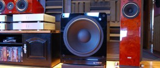
The basis of my home audio system since 1991 has been the Priboi 50UM-204S tube amplifier with Soyuz 130AS-002 speaker systems.
The output stages of the amplifier use push-pull circuits based on powerful 6P3C beam tetrodes. The speaker systems are connected to the amplifier using an inexpensive Chinese-made speaker cable. All connecting cords are homemade. There is a vinyl collection, but usually I listen to music from CDs. I really love tube technology and I am very upset by pointless debates on the topic of what is better: “vinyl” or CD, tubes or transistors, triodes or pentodes, etc. I hope my publication will help bring some clarity to the subject area and introduce some of these discussions into a constructive direction.
♪ Tube audio preamplifier board. Looking for warmth...
Good afternoon, dear readers. I never thought that I would write this review. But curiosity got the better of me. Yes, yes, today we will look at the Chinese warm tube sound. Namely, let's look at and listen to the audio pre-amplifier board. Chinese manufacturers are positioning this device to improve and “soften” the sound of the digital path. “This allows for significant improvements in the sound of any CD player by optimizing inductive, capacitive and resistive loads. This buffer can also be included in any linear circuits." Package:
Lamps are not included!
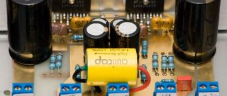
Board appearance:
All elements are already sealed. The capacitors look decent. This is a pre-amplifier that is connected between the sound source and the power amplifier. By type it is a regular single-cycle, two-stage with OOC. Bottom:
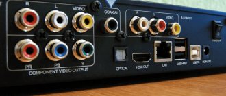
The flux has been partially washed off. Rear connectors:
Linear input and output on tulips and a 5.5x2.1 mm connector for the power supply.
Power
supply required AC 12V 0.5A. Front:
The lamps are placed in sealed sockets:
Voltage multiplier capacitors:
The lamp anode is powered through it. For those interested, finishing the board up.
Traditionally for the Chinese, this is a clone of the X-10D Musical Fidelity preamplifier:
It is interestingly designed in a cylindrical body.
The scheme is the same:
The Chinese also sell a ready-made clone, a packaged version:
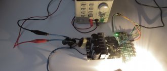
I found a transformer to check:
Transformer
Since the board does not come with lamps included, you need to get them somewhere. From China it takes a long time, and as it turned out, it was expensive. And why do we need some 6N11 or ECC88 when we have the original 6N23P. Then the scheme is simple - Avito and search in your area. I assure you, there will definitely be a guy who filled a garage full of these lamps at one time. In my area I also found:
In short, I have the lamps within a day and at a reasonable price. You can, of course, find it in stores or flea markets, but through Avito it’s more modern or something.
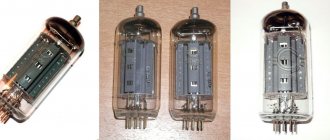
Double triode 6n23p:
Oh, like new!
Install in the panel:
Listening:
Turn on: The lamps are illuminated from below with a blue LED, I would be surprised if it were not there.
Speaking of heat, the lamps get quite hot during operation. During the hour of listening, my hand couldn't stand it.
I listened several times. The music was different, both retro (Sinatra, Presley, jazz) and just instrumentals and high-quality pop. FLAC format, solid state player source. Acoustics AVA one Alexandrov.
According to the manufacturer’s idea, all digital abomination and “filth” should be softened by the warmth of the lamps. But my path is quite modest in terms of distortion and the “dirty” came from the pre-amplifier. The highs were dull, and distortion in the lows affected the dynamic range. It’s good that I didn’t make a housing for the board, I thought.
Testing:
Generator test: Rectangle:
Sinus:
Output noise:
RMAA measurements:
Frequency response:
THD:
I wanted to listen to warm tube even harmonics, but what I got was some kind of soulless transistor fence. Of course there is the influence of the card and wires, but not to the same extent. Difference in harmonics of lamps and transistors:
Conclusions:
If you want to soften the sound of your HI-FI equipment, pour 50 ml of good cognac into your glass. Excellent effect, better than Chinese lamp crafts.
Coupon 3/25 for those who want to buy
Thank you for watching. Happy shopping and only high-quality sound!
The product was provided for writing a review by the store. The review was published in accordance with clause 18 of the Site Rules.