Continuity of wires
If the cable breaks, as well as in other cases, it is necessary to determine which wires are connected to the headphones, microphone and control buttons.
There are certain wire color standards that manufacturers adhere to, although they may be violated:
- colorless (copper) - common wire;
- red - right channel;
- green - left channel;
- blue - microphone;
- other colors - control panel (buttons, or “rocker”).
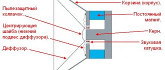
Depending on the model, the wires to the microphone and control panel can be combined or separate, and in different elements of the headphones there can be one or more common wires. A shielded wire can go to the microphone.
Recommendations: How to solder a headphone plug
, How to disassemble headphones: instructions with step-by-step photos of repairing all elements of the headset
, Headphone pinout
Wire distribution depending on color
It is impossible to carry out high-quality repairs without determining the exact location of the cable break. Next, you need to identify which of them go to the speakers, microphone and control button. The color of the braid makes this task easier, but some manufacturers change this indicator, since there is no uniform standard. Most common color combination:
- clear braided cable is common;
- the right channel is indicated in red;
- green indicates left channel;
- blue goes to the microphone, and it is almost always shielded;
- Any other color indicates cables with a switch button.
Some manufacturers prefer to combine cables going to the volume control buttons and microphone.
How to ring wires
The wires going to different parts of the headphones can be tested using a tester. First of all, you need to find the ones going to the speakers:
- Strip all wire ends. In some models, the wire going to the microphone is shielded, where the screen plays the role of one of the wires.
- Put on headphones. A crackling sound will be heard in the speakers when connected to the tester. If it is in only one speaker, then the tester is connected to one of the channels and the common wire. If a crackling sound is heard in both speakers, then the tester is connected to two channels, without a common wire.
The following are possible options:
- With four wires in the cable, the remaining one is connected to the microphone and control panel.
- With five wires, if the remaining two communicate with each other and do not communicate with the speakers, they are connected to the microphone along with the control panel and the common terminal. If the remaining ones call with the others, then they are soldered together to the microphone terminal.
- With seven wires, the remaining four are connected in pairs to the microphone and buttons. They are soldered by color, to the common and microphone terminals.
DIY headphone repair
Headphone wiring
The most common plug is a 3.5 mini-jack. But besides it, a 2.5 jack is used, as well as miniUSB and mikroUSB.
Wiring for 2.5 and 3.5 jack plugs
There are only three wires in a regular headphone cable. A plug with this number of pins is also called TRS. The numbering goes from tip to cable:
1 - left channel;
2 - right channel;
3 – general.
Instead of three wires, there may be four (two pairs). In this case, one wire from each pair of the same color is considered common and soldered together.
The wiring on such a plug is very simple - the contact ring closest to the cable is common, the remaining ones are the right and left channels. In a standard wiring, the right channel is connected to the middle ring, and the left channel is connected to the end of the plug.
Solder the wires to the appropriate soldering spots. They can be determined visually or with a tester.
The 2.5 plug is designed similarly to the 3.5 and is no different from it except for its size. The wiring is the same on both plugs.
Wiring in miniUSB and miniUSB plugs
In some mobile phones, headphones with a microphone are connected via mini- and mikroUSB connectors. But you can also connect just headphones to these connectors, for example, to use such a mobile phone as an MP3 player.
The wiring in these connectors is the same. They have five pins to which wires are soldered. They are numbered from left to right when viewed from the side where the wires are connected, and the wires are soldered to 1 (common), 3 (right channel) and 4 (left channel).
Wiring in a headset - headphones with a microphone
In addition to regular headphones, which only have speakers, there are headphones with a built-in microphone and control buttons. The cable of such devices has a large number of wires - from four to seven.
Wiring in the 3.5 plug
These plugs have the technical name TRRS. There are two options for wiring these devices OMTP and CTIA. They differ in the connection of the microphone and the common wire, which connect to 3 and 4 wires.
If you connect the wrong type, the microphone will not work and the sound will be muffled.
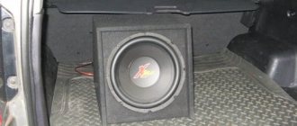
Installing a subwoofer in a car with your own hands
When we have already decided on the choice of a subwoofer and purchased it, we need to check the availability of cables for connecting the amplifier and fuse.
We will need:
- power cable “positive” (usually red);
- power cable “minus” (usually brown or gray), the so-called “ground”;
- RCA cable with double shield (tulip ends);
- control cable, also known as recognition cable (thin, about the thickness of a match, usually black or blue);
- two-core acoustic cable;
- AGU fuse and bulb for it;
- round and spade terminals, nylon clamps.
The price of the set is 800 rubles. You can buy it cheaper, but the cable fastenings there are unreliable.
Before starting installation, I recommend removing the negative terminal of the battery, thereby eliminating the possibility of electric shock.
Let's start with connecting the power part, the most labor-intensive. First, we pull the positive power cable from the trunk into the engine compartment, to the positive terminal of the battery. The positive cable is usually red, cross-sectional diameter 5-6 mm, about 5 meters long. To do this, we run the cable into the trunk, leave the required length to connect the amplifier, preferably with a small margin, then run it under the left side of the rear seat of the car. It is not necessary to remove the rear seat back, just lift the seat itself.
So, we pass the cable from the trunk under the back of the rear seat, I repeat on the left side, we pull it further under the driver’s seat. Here it is up to your discretion - you can carefully drive it under the casing. I will do this when installing sound insulation, but now I just let it go under the rugs. So, we run the cable under the driver's seat to the pedals. Now we need to pull the cable into the engine compartment. In Renault Logans, the best option for pulling the cable into the engine compartment is through the wiring harness plug. We find a rubber plug with a thick wiring harness above the clutch pedal.
Then we make a hole in it necessary for pulling the cable and begin to push it inside. Then we open the hood, and behind the expansion tank we find this same wiring harness with a plug, take the end of the cable, which should already appear from the plug, and pull it out to the required length to the battery, not forgetting to leave a small margin.
Now let's install an AGU fuse on the positive cable.
Usually it is already in the flask, if not, you need to insert it into the flask. We measure 30-40 cm from the end of the cable that we pulled into the engine compartment and cut off this piece.
Then on one side of the fuse we connect the end of the cable from which we cut off a piece, and on the other this same cut piece, and it turns out that we inserted it into the wire. There are a variety of options for attaching fuse terminals, usually simple. We fix the fuse at a distance of about 30 cm from the battery.
Now we strip both ends of the cable from insulation and attach it to the end in the engine compartment, which we will attach to the plus of the battery with a spade terminal, and to the end in the trunk, which we will attach to the amplifier with a round terminal. For reliability, we tape the terminals to the cable with electrical tape and connect the end that is in the trunk to the positive terminal of the amplifier (do not mix up the polarity!). Sometimes the positive terminal is labeled SUPPLY, we fix it. Then we connect the negative cable, the so-called “ground”.
The negative cable is usually short, about a meter long, brown, black or gray. Similarly, we strip the ends of the cable from insulation, attach the terminals in the same way - a round terminal on the end connected to the amplifier terminal, attach it to the negative terminal of the amplifier, sometimes it is labeled GROUND, and attach the other end, where we attached the spade terminal, to some part of the body or bolt.
I attached it to the bolt that is supposed to hold the trunk trim, located right next to the tailgate, on the side of the rear optics mount. The mounting location must be cleared of paint and foreign materials. secure with a nut and move on to the next part of the installation.
Now, having connected the power part, let's connect the sound part. To do this, take a control cable or recognition cable. It is usually thin, matchstick thick, about 5 meters long, blue or black. It is needed so that the amplifier turns on and off simultaneously with the radio.
In the same way as we pulled the positive cable, we begin to pull it from the trunk, BUT we only pull it to the center console, where the radio is located, and this time we pull it along the right side of the cabin.
It is important to keep the power cables away from the audio cables, otherwise there will be interference when playing music. Therefore, we pull in the same way but along the right side of the car interior, the more convenient it will be to connect to the radio from the right side.
Having stretched it to the center console, we take out the radio, put the cable from the back of the console into the pocket for the radio, again at your discretion - you can drive the cable under the trim. Now we find a blue or blue-white wire on the radio in the general bundle of wires; sometimes the place where it is connected has the inscription ANT.
On modern radio tape recorders, this wire already has a prepared tap for connecting an amplifier (this is exactly what I have). So, if there is such a branch, we strip the ends and connect them to the end of the control cable. if not, then pull it out, wind it with the end of the control cable and insert it back.
Then we return to the trunk, strip the end of the cable and connect it to the REMOTE terminal on the amplifier (may be called differently, sometimes marked with an open circuit key icon, most often located between the power cable terminals).
Now we take the RCA cable, which has two “tulips” at the ends, mine is orange, and pull it from the trunk to the radio in the same way as the previous cables and similarly to the control cable on the right side.
On the back of the radio, we find two linear outputs for “tulips” (modern radios have them) and insert them there (if possible, by color). From the other end of the cable, we insert the outputs into similar ones on the amplifier, observing the polarity (or colors, or left with left, right with right).
Now we put the positive terminal of the battery in place, connect the positive terminal of the power cable to it
We turn on the radio. Has the power light on the amplifier come on? Turned off the radio. Has the lamp gone out? This means the amplifier is working and everything is connected correctly. if not, then check the reliability of the fastenings, try to clean the place where the “ground” is attached.
So, the last step remains - connecting the amplifier and subwoofer, since ours is passive. We take an acoustic cable (it is two-core, about 5 meters long, the cross-sectional thickness is about 1.5 mm, cut it to the required length. Then we strip the ends of the cable and connect one end to the BRIDGE MODE terminals on the amplifier, the other to the terminals on the subwoofer, observing the polarity.
Turn on the radio and enjoy the low frequencies. If you wish, you can output it to the amplifier and speakers, but in my opinion it is better to leave them connected separately.
We carry out the final work, remove the wires under the casing, secure and configure the amplifier and subwoofer to your taste and go and enjoy.
What I can recommend:
1. First, immediately take high-quality wiring - made of copper. Even if you choose a budget option. The wiring a la Mystery is made of aluminum, and from the physics course we know that the resistance of aluminum is quite high. People use KG welding cables as power wires quite successfully. The money will work out the same. Although it is generally advisable not to mess with Mystery, it is better to take normal components right away. And crimp the terminals properly.
2. Secondly, tuck the power cables into the corrugation. The first time I didn't do this.
3. Don't waste money on capacitors and other similar gadgets.
4. Secure the amplifier and subwoofer normally in the trunk.
Connecting a headset to mikro- and miniUSB plugs
In some phones, headphones are connected not to a 3.5 plug, but to a mikro- or miniUSB connector. There is also a standard when connecting to the terminals of such plugs. They are counted from left to right when viewed from the side where the wires are connected:
1. common wire;
2. microphone, as well as control buttons;
3. right channel;
4. left channel;
5. not connected.