Unfortunately, a small percentage of all manufacturers of large-sized musical equipment often release updated versions of their products. Especially when it comes to speaker systems. Such devices have a complex design, high cost and, accordingly, a high price on the market. Therefore, manufacturers rarely take risks by initially creating the version that fans would like to see. Really worthwhile models often appear at specialized points of sale. They will amaze everyone with their design and technical characteristics. The implementation of such nuances may be different for all manufacturers, but for the buyer it does not matter. Therefore, for any company, the main goal is to fully satisfy all requirements. And if we talk about such a task, it must be said that the Yamaha NS 6490 device, the review of which will be presented in this article, causes controversial feelings. Some buyers appreciate the good appearance and excellent performance, while others mention the impracticality of use. We'll talk about all this in more detail later.
general information
Many buyers are surprised by the fact that the speakers are inexpensive, but at the same time they are considered a full-fledged three-way system. It is equipped with filters. If you believe the company's statements, the decision to make the speakers exactly like this allowed them to reduce the amount of distortion to minimal levels. Due to technical implementation, which was limited, only the price decreased. On the one hand, this is an advantage, but on the other hand, some consumers will have to manually improve the Yamaha NS 6490. Refinement of the filter, as a rule, is carried out immediately, as this solves many problems. If you wish, you can improve the insulation. Speaking of sound, it should be noted that reviews about it are controversial. Paying attention to the price category as a whole, the playback quality is normal. The model is in demand in America and Japan precisely because of this, even though the market and budget segment is regularly replenished with new products. Buyers also like the design. It has a bit of a retro feel to it, which helps it appeal to a certain crowd.
Circuit and design of a series filter for speakers Yamaha NS-6490 (part 2)
Continuation of part 1 of the article “Theory and calculation by the phase method of a sequential filter for speakers”
1. Circuit and characteristics of a serial filter
Figure 1 shows a diagram of a sequential 3-band “quasi-second” order filter, developed using the phase method in order to bring the phases of the speakers as close as possible to each other in terms of current in adjacent areas of operation in the most important frequency range for stereophonic sound reproduction, 0.2…6 kHz for a specific speaker “Yamaha NS-6490”. To determine the optimal values of the filter parameters, the “Qucs” circuit simulator [2] was used using speaker models (see Fig. 1 in the 1st part of the article).
Fig. 1 Schematic of a first (“quasi-second”) order sequential filter developed for the Yamaha NS-6490 speaker. The mid-frequency speaker (Rdsch) is switched on out of phase with the LF and HF speakers.
This is a first-order sequential filter based on the values of the parameters of the oscillatory links L1C1 and L2C2, corresponding on average to the selected value of the damping coefficient Kd = ~ 0.5 (see 5.4 section 1 of part of the article). refers to the so-called “quasi-second” (“almost second”) order with a variable filter resistance over the range of reproduced signal frequencies, decreasing almost twice relative to the nominal resistance of the speakers in the mid-frequency range [1...5.3 kHz], specified resonant frequencies of links L1C1 (1 kHz) and L2C2 (5.3 kHz).
The frequency characteristics of the proposed filter combine the properties of second-order oscillatory units in the mid-frequency region, and beyond them its properties smoothly transition to the frequency properties of first-order filters, while the filter itself still belongs to first-order filters and due to this has excellent properties for high-quality reproduction of pulse signals, which fully includes a musical signal. Filters of the second and higher orders, often used in parallel filters, do not have such unique properties and do not reproduce pulsed signals well, which is their main drawback (see Fig. 10 in part 1 of the article).
The selected “quasi-second” order parameters made it possible to implement in the filter an increased steepness of the band separation fronts for low-frequency (LF) and high-frequency (HF) filters on average ±50 dB/decade for voltage and ±72 dB/decade for current, and for the average frequency (MF) filter ±18 dB/decade for voltage and ±36 dB/decade for current (see Fig. 3).
As a result, this series filter was able to combine the best properties of first- and second-order filters, but with the additional feature of reduced resistance in the mid-frequency region. To partially compensate for this reduced resistance, a powerful equalizing resistor R1 is included in the filter circuit (Fig. 1), which reduces the relative resistance difference of speakers with such a series filter, and also helps to reduce nonlinear distortion in the power amplifier (see Section 1, Part 1 of the article).
This filter is proposed to be installed instead of a simple standard speaker filter "Yamaha NS-6490", consisting of only two bipolar capacitors with a capacity of 4.7 μF and 1.5 μF, connected in series to the midrange and high-frequency speakers, respectively.
Let us remind you that the midrange speaker in this series filter must be connected out of phase to the bass and treble speakers (by the way, in the standard filter the midrange speaker is also connected out of phase to the other speakers).
Three subroutines with the names SUB1...SUB3 drawn in the diagram in Fig. 2 contain diagrams of models of high-frequency, mid-range and low-frequency speakers that approximate in general their frequency properties, obtained in the absence of filters and measured on the website [1] (see diagrams of these models in Fig. .2 in section 3 of part 1 of this article).
Resistors R_L1 and R_L2 take into account the active resistance of the inductors L1 and L2 for direct current. The diagram adds current meters (PriB, PriC, PriH) and voltage meters (PruB, PruC, PruH) for all three speakers and a meter for the total current consumed from the power amplifier (PriUMZ4). The circuit entry point (in the upper left corner of the circuit) called in also measures the input voltage in.v [V].
To the right of the diagram are all equations for recalculating the amplitudes of current and voltage vectors in [dB] (using the standard functions of the circuit simulator dB(...)) and calculating the phase angle using the phase(...) function. To calculate the sums of voltage and current vectors, the corresponding equations are also used.
Fig. 2 Scheme for modeling the frequency characteristics of a series filter on alternating current in the “Qucs” circuit simulator [2].
Fig.3 Frequency characteristics of a series filter based on voltage and current flowing through the speaker coils. Accepted designations: for the woofer - blue, midrange - red and treble - crimson. The vector sum of voltages and currents for all three speakers is shown in green. The current consumption from the power amplifier is shown in bluish color.
The phase characteristic of the current in the speaker coils (in the two lower graphs in Fig. 3) was obtained by changing the sign of the initial phase of the input signal (from (+) to (-) at the input signal source “V1” in the upper left corner of the diagram in Fig. .2), in order to clearly show the nature of the group delay time, in contrast to the above figure in the middle row with a break in the graph at 1.6...1.8 kHz, obtained with the (+) phase of the input signal.
These discontinuities in the behavior of the phase graph, which seem to be jumps in phase by ±3600, are absent in the behavior of the real phase graph and are only algorithmic in nature and are caused by the desire of the circuit simulator developers to limit the output of phase angle values to a fixed range not exceeding [-1800...+1800]. For example, in the lower left figure, when the phase of the woofer in terms of current decreases as the frequency increases from 100 Hz to 200 Hz and begins to move from -1800 to -1810, the phase angle calculation algorithm begins to add from this moment to the true phase angle +3600 to limit the displayed angle value in the range [-1800...+1800], which leads to an apparent phase jump from -1800 to +1800, which in fact is not present in the behavior of the true phase angle, which continues to smoothly change from -1800 to -1810 and beyond. A similar jump occurs when the phase angle increases in the other direction from +1800 to +1810, when 3600 begins to be subtracted programmatically from the true phase angle (see the left middle figure with the phase graph for the voltage of the raspberry-colored tweeter in Fig. 3). Therefore, in order to better understand the true behavior of the phase graph by frequency in places where the phase graphs jump by ± 3600, you need to mentally move the upper or lower parts of the phase graph, combining them at the break points.
Fig. 4 Transient process in a series filter (response to a step signal of 10 V lasting 2 ms), with the midrange speaker normally connected in antiphase to the bass and treble speakers.
Pay attention to the good restored shape of the input “meander”, obtained in the form of a vector sum of the voltages on the coils of three speakers (green rectangles in the left figure) in this filter (a slight difference from the rectangular shape is caused by the influence of the equalizing resistor R1 = 2 Ohm Fig. 1), despite its “quasi-second” order, since it is known that filters of the second and more orders cannot correctly restore the appearance of the input rectangular “meander” by voltage by the sum of their own filtered filter bands, but a sequential “quasi-second” order filter does this flawlessly correct, like all first-order filters (for more details, see Fig. 11, part 1 of the article).
The lower right in Fig. 4 shows the processing of the rectangular input voltage “meander” by the currents in the speaker coils (the vector sum of the three speaker currents is shown in green, and the total current consumption from the amplifier is bluish).
From Fig. 4 it is clear that the delay in the processing time of the input step current signal is ~ 0.28 ms, which is confirmed by the same group delay time (tgr.reset = 0.28 ms) according to the frequency characteristics of the alternating current filter on bottom right picture Fig. 3.
The simulation of the frequency characteristics of this speaker with a standard filter with different activations of the midrange and high-frequency speakers (in phase and antiphase) can be found in Section 3 of Part 1 of the article.
2. Filter design
Fig. 5 shows a photograph of a filter made in dimensions that allow it to be installed inside the speaker housing through a structural cutout made for a panel with input terminals on the rear wall of the housing (see Fig. 6).
Fig.5 Photo of serial filter board
The filter is installed inside the speaker housing from the rear side of the speaker through a proprietary structural rectangular cutout (Fig. 6), made for a panel with speaker input terminals in the rear wall of the housing measuring 72 mm by 60 mm (after removing the panel by unscrewing four screws). Dimensions of the filter board with installed parts: length ~314 mm, width 71-72 mm and total height no more than 58-59 mm with the thickness of the board's three-layer plywood included in this height (~4 mm) and the wires protruding from the back of the board for fastening the parts to board
Fig.6 Sketch of the placement of the filter board inside the body of the Yamaha NS-6490 speaker after its installation.
The length of the board was determined experimentally and amounted to ~314 mm so that it could be installed through this cutout inside the case diagonally downwards, resting the front end of the filter board against the lower edge of the line where the front panel of the speaker meets the speakers and the bottom of the case. In this case, the rear upper end of the filter board rests on the lower edge of the cutout in the rear wall of the speaker housing from the inside with a minimum protrusion of ~ 1-2 mm, so that the panel with input terminals can be inserted back into place and thereby fix the position of the filter in the speaker housing without using any fastening of the filter board (see Fig. 6).
Inside the case at the bottom on the lower edge of the junction of the front and bottom sides, a reinforcing bar of triangular cross-section less than 50 mm long is very successfully glued structurally, under which a cutout ~52 mm wide was made in our filter board on its right end in Fig. 6, which made it possible to exclude the possibility of moving the front end of the filter board along the lower edge of the junction of the front and bottom walls of the speaker housing. If desired, you can additionally glue a layer of foam rubber or thin rubber to the ends of the filter board to seal the fixation. However, taking into account the decent mass of the filter (~0.6 kg), the author did without using a seal.
This design of the filter made it possible to get rid of the need to dismantle (remove) the woofer from the front panel of the speaker to place the filter inside the housing and the subsequent mandatory replacement of the seal under it when it is put back into a closed box using, for example, a thin rubber self-adhesive pad made of soft rubber used for sealing entrance doors. We must not forget that this speaker uses a closed and sealed housing to provide acoustic damping (resistance) to the low-frequency dynamics due to the elasticity of the internal air volume, and therefore the presence of cracks is not permissible due to a decrease in damping properties.
3. Inductors
The most massive parts are two inductors L1 and L2 with air cores as the highest quality, without the use of any additional metal cores inside the coils, which can lead to nonlinear distortions with a large output current. Moreover, the inductances are relatively small in size. The inductance of the low-frequency coil L1 is 0.64 mH, and the inductance of the second coil L2 is quite small: 0.09 mH.
The inductors are wound with copper wire in varnish insulation on standard thin-walled (with a wall thickness of ~0.6 mm) round coils of industrial production, which were found under the name “Frame coil under Ch 48” [5]. The coils have the following dimensions: internal diameter ~22 mm, internal width ~17.5 mm and external diameter of the side cheeks ~39 mm.
The outer diameter of the cheeks of the coils turned out to be too small and therefore they had to be increased by gluing additional cheeks from the inside to the inner side cheeks of the coil so that they would not come off when winding the wire. New glued cheeks increase the outer size of the coil cheeks to a square measuring 56 mm by 56 mm, so that it is easier to fix the L2 coil with the flat ends of the cheeks on the board and limit it to the maximum possible height of 56 mm (taking into account the thickness of the board of 4 mm), so that fit the cross section of the filter board along the height of the window cutout ~60 mm and its width ~72 mm.
Outdated conventional computer floppy disks (1.44 MB capacity) with a flexible magnetic disk were well suited as a source of thin and durable material for additional coil cheeks. The plastic of black floppy disks turned out to be especially durable (colored and transparent ones more often cracked like candy when they were cut out). A square with sides 56 by 56 mm was cut out of the floppy disk using scissors around the central hole of the floppy disk with a diameter of ~27 mm, which was suitable in diameter for gluing from the inside to the cheeks of the original coil. There is no such hole in the back wall of the floppy disk and it must either be carefully cut out with small pliers, or use another floppy disk. Due to the split part of the floppy disk by careful elastic extension in different directions, an additional wall from the floppy disk passes inside our reel, pre-lubricated with glue from a gray tube called “Transparent Moment” and intended for gluing various plastics. Additional cheeks cut in one place along the radius must be glued to the inner sides of the coil cheeks, since the pushing force of the wire when winding onto the frame is very large and the external gluing may not withstand.
The method for manually calculating the required number of turns depends on the ratio of the coil sizes and is described in great detail in the book by S.V. Gaponenko on pp. 160-167 [3]. You can simply use the excellent “KFAS” calculator to calculate the parameters of the filter and inductors [9].
To wind the inductance L1 = 0.64 mH on the frame described above, ~163 calculated turns of PETV2 enameled copper wire with a diameter of 1.18 (copper diameter excluding the thickness of the varnish coating) were required with an active resistance to direct current of ~ 0.36 Ohm. To wind a coil L2=0.09 mH, a larger diameter wire of ~ (1.5…1.7) mm is required with a number of turns of ~ 65 turns and an active resistance of ~0.06 Ohm.
It is not recommended to use smaller wire diameters due to an increase in the active resistance of the coils to direct current, which limits the possibilities for phase convergence between the speakers. In addition, the small active resistances of the inductances L1 and L2 also play a second important role as shunt protection for the coils of HF and midrange speakers in the event of an emergency appearance of direct voltage from the power supply at the output of the UMZCH in the absence of a protection unit in it. In this case, the magnitude of the emergency current will be determined by the sum of the resistances of the equalizing resistor R1 and the woofer coil, and both inductances, shunt coils of the midrange and tweeter speakers will protect their thinner wires from burnout, passing through them no more than 5% and 0.04% of the emergency current respectively.
When choosing a different size of the coil frame, it is necessary to increase the calculated volume of the coil for the wire by a spare 10...15% due to the inevitable looseness of the wire winding, especially in the outer layers of the coil, since it is quite difficult to wind “spreading” turns of wire in even layers manually without using tape between the layers of the coil .
When calculating the direct current resistance of an inductor, the resistivity of copper can be taken equal to 0.0175±0.0005 Ohm mm2 / m, and to estimate the required mass of copper wire when ordering it (based on the estimated length of the coil wire, equal to the product of the number of turns times the average the length of the turn with a small margin of 5...10%) the density of copper should be taken equal to 8.92 g/cm3.
The production of two copies of inductor coils L1=0.64 mH required approximately ~ 37 m (weighing ~ 0.4 kg) of PETV2 enameled copper wire with a diameter of 1.18 mm, and for two coils L2 = 0.09 mH it was necessary ~15 m ( weighing ~ 0.3 kg) PETV2 wires with a diameter of 1.5…1.7 mm. All of one filter assembly weighs 0.6…0.7 kg. To order a relatively inexpensive (several times cheaper) PETV2 wire, I recommend using the services of the website [6] with delivery within 3-4 days after payment of the order.
In the absence of an inductance meter, it is quite acceptable to wind according to the number of calculated turns, calculated for the internal dimensions of your coil. Only in this case it is necessary to try to wind both coils with the same number of turns, accurate to the turn, in order to ensure good equality of inductances between the two stereo channel filters.
It’s even easier and more reliable to order the production of coils on the website [10], indicating in the order your data on the inductance value, wire diameter, the maximum permissible outer diameter of the coil with a fully wound wire and the selected type of its frame, since the excess size of the cheek frame can be easily filed, taking into account the restrictions on the size of the L2 coil cheeks of 56 x 56 mm.
It should be noted that any metal rod (even a non-magnetic one, made of aluminum or copper) in the middle of the coil has a significant effect on the value of its inductance, so you cannot attach the inductance coils using metal screws and washers to the board, as is done when attaching toroidal transformers. The filter parts must be fastened to the board either with wire insulated in plastic or with synthetics, for example, PVC tape, thick threads or fishing line, drilling holes with a diameter of 1.5...2 mm in the right places. It is also advisable to avoid fastening the coils with copper wire in varnish insulation due to the risk of the formation of short-circuited turns when twisting the wire; it is more reliable to use a thin mounting copper wire in a plastic sheath.
For example, when winding inductance on a tube made of a plastic water pipe with an outer diameter of 20 mm with an internal thin aluminum tube with a wall thickness of ~0.3 mm), the author tried to measure the inductance of the coil with the device without removing it from the pipe, which, however, led to an underestimation measured inductance (compared to the inductance of a coil without an inner tube). The error in such measurements was equivalent to winding ~ 5...8 extra turns, and this is quite a lot of inductance, taking into account its quadratic dependence on the number of turns.
As a result, even a very thin aluminum tube in the center of the coil underestimated the inductance value of the wound coil. By the way, in VHF radio receiver units, the inductance of the coils is often adjusted using threaded cores made of copper alloys. Therefore, when attaching inductors to the board, it is unacceptable to use any metal screws, including those made of non-magnetic metals, for example, aluminum or copper alloys (although their use “as a last resort” is allowed by S.V. Gaponenko in his book [3] on p. 163).
Taking into account the small dimensions of the board, it is necessary to strive for the maximum possible reduction in the inductive coupling of electromagnetic fields between two inductors L1 and L2, accompanied by mutual electromagnetic induction of currents from one coil to another, which leads to unwanted cross-penetration of signals from one frequency band to another, thereby reducing the depth of band separation between frequency filters.
The rule for the mutual placement of coils is the maximum possible distance between the centers of the coils from each other (at least 5-8 cm, and preferably 10 cm) and the mutual perpendicularity of the axes of the coils in space according to the following rule: the longitudinal axis of the second coil must be turned perpendicular to the plane drawn through the centers of both coils and the longitudinal axis of the first coil.
Therefore, in the design of this filter in photo Fig. 5, the first coil L1, as the heavier one, is fixed flat on the board (on the left), and the second coil L2, located to the right of it at a distance of ~10 cm between the centers of the coils, is installed perpendicular to the board and stands on the sides cheeks with a longitudinal axis perpendicular to the vertical plane passing through the vertical axis of the first coil and the centers of both coils.
4. Capacitors
It was decided to select the capacitance of the capacitors from domestically produced film capacitors of the K73-17 type with a capacity of 4.7 μF at 63 V as they are very good in terms of minimal introduced distortion [4], as well as providing the smallest dimensions (due to their rectangular shape) and minimal the cost of capacitors C1 and C2, collected due to their parallel connection. Slightly better in quality, but more expensive and larger, cylindrical film capacitors of the K73-16 type.
To obtain the required capacitance values for C1 = 40...43 µF and C2 = 10 ± 0.5 µF, the above-mentioned K73-17 capacitors, after measuring their actual capacitances, were collected into cassettes for the left and right channels with close total capacitance values. A flexible and thin-walled plastic finishing corner was used as a container for placing the capacitors with PVC capacitors secured in it with electrical tape. In photo Fig. 5 along the rear wall of the filter you can see the leads of these capacitors, soldered to two wire buses to obtain the required value of the capacitance of capacitor C1. When using a powerful high-voltage UMZCH with a bipolar power supply of more than ±50 V, higher-voltage similar imported film capacitors rated for voltages up to 100 V should be used.
5. Wiring the terminal block and connecting the filter
The photo of the board (Fig. 5) shows a 7-pin domestic block with pins numbered from left to right from No. 1 to No. 7, of which contacts No. 2 to No. 7 are intended for soldering wires from speaker coils, taking into account the phase (+) and ( -) their wires, and wires are soldered to contacts No. 1 and No. 7, coming respectively from the (+) red and (-) black terminals, to which the output signal from the UMZCH is supplied.
At the bottom left of the photo, a 5-watt equalizing resistor R1 is soldered to contacts No. 1 and No. 2, the value of which in the author’s filters was selected with a higher value of 4.7 Ohms (instead of 2 Ohms according to the diagram).
To reduce heat generation on it, lovers of high output powers (~ 100 W) can, in principle, refuse to install the equalizing resistor R1. But at the same time, they must clearly understand that resistor R1 is necessary to compensate for the almost twofold decrease in the filter impedance at medium frequencies due to the halved characteristic impedance of each of the oscillatory links L1C1 and L2C2 due to the low value of the Kd coefficient chosen when designing using the phase method =~0.5.
In the absence of resistor R1, which equalizes the differences in the impedance of the speaker, the UMZCH will operate in rather difficult conditions with a reduced load resistance (impedance) of ~ 3...4 Ohms at medium frequencies, which is approximately two times less than the resistance of this speaker ~ 6...8 Ohms with standard filter, therefore the UMZCH itself must be designed for long-term operation with high output power with such a reduced impedance, and the user takes on the risk associated with the reliability of the UMZCH operation in this mode.
This is perhaps the main feature, which is a disadvantage, of this “quasi-second” order series filter, to compensate for which the equalizing resistor R1 was introduced. Still, it is strongly recommended to install equalizing resistor R1 with a value of at least ~ 2 ohms, and even better 4...5 ohms. The advantages and disadvantages of installing an equalizing resistor are described at the beginning of part 1 of the article. Since the author used data from the Internet [1] when creating electrical models of speakers and did not measure the real ratio of the maximum values of the levels of bass, midrange and high-frequency speakers of the speakers using a measuring microphone, users can decide for themselves the question of the required value of the equalizing resistor R1, which, for example , with an increase of every 2 Ohms can reduce the initial difference between the maximum sound levels of the LF and (MF and HF) speakers (if there really is one) by ~3.0 dB (see the top figures with R1=0 and R1=2 Ohms on Fig.3).
The photo of the filter board in Fig. 5 is a little outdated. So, the filter does not need a pair of resistors (in fractions of an Ohm), located at the top left between the lower terminal of the coil L1 and the capacitor C1 (see diagram in Fig. 1). And therefore, it is necessary to directly connect the output of coil L1, which is lower in the diagram, with a mounting wire to the combined contacts No. 5 and 6 on the block (counting the contact numbers from left to right), and capacitor C1 must be connected, as shown in the photo, with its own separate wire to the same contacts, in order to separate the currents of the two filtered bands through different wires for their better electrical isolation to the point of their union at contacts No. 5 and 6, where the positive terminals of the bass and midrange speaker coils are connected.
In the 2022 Yamaha NS-6490 speakers, each pair of wires from three speakers has the following colors and markings:
Woofer: paired red (+) wire and black-red (-) wire;
Midrange speaker: blue (+) wire and black-blue (-) wire;
HF speaker: yellow (+) wire and black-yellow (-) wire;
All these three paired wires coming from the speakers must be unsoldered from the terminals of the standard filter capacitors and input terminals, and then soldered to contacts No. 2 to No. 7 of the block.
Due to the limited length of the wires from the speakers and the author’s reluctance to increase their length, soldering the wires to the filter block was done with the filter board half inserted into the speaker housing. In this case, first, using a pair of additional wires, we connect the signal from the amplifier from the input terminals (+) red and (-) black, respectively, to contacts No. 1 and No. 7 of the block, and then we solder the wires from the speakers to contacts No. 2 to No. 7, taking into account the above color marking of wires and according to the inscriptions under the block in the photo Fig. 5.
At the same time, we must not forget that the midrange speaker must be turned on in antiphase to the low-frequency and high-frequency speakers, as can be seen from the (+) and (-) signs on the inscription under the contacts of the block.
on the basis of this good set of speakers, it released two more floor-standing and outwardly identical models under the names “NS-7390” and “NS-8390” with ~ twice the volume of the body and with shortened bass reflexes and formally with the same cutoff frequencies of capacitive filters 2.5 and 8.0 kHz, like the NS-6490, in the form of two bipolar capacitors, but with different capacitances of 2.2 μF and 1.2 μF (instead of 4.7 and 1.5 μF for the NS-6490) . The proposed serial filter is mainly suitable for these models. Although it is still desirable to clarify the frequency response model for the low-frequency speaker in this new acoustic design (models for the midrange and high-frequency speakers do not require clarification, since they will not change due to their closed, sealed design in individual boxes) and search for the final optimal values of the filter elements for these speaker models according to the criterion of maximum convergence of the phases of the speakers to each other in adjacent areas of operation in frequency.
Article2
6. Estimation of the cost of parts when making a filter yourself
1. Frame reel under Ch 48, “Chip and Dip” [5] (with modification of the cheeks), 40 rubles/piece, 4 pieces – 160 rubles
2. Copper enameled wire PETV2 from “snabcable.ru” [6]:
Wire with a diameter of 1.18 mm, ~0.4 kg (~37 m) for two coils L1, price 1 kg -923 rubles, - 369 rubles
Wire with a diameter of 1.50...1.7 mm, ~0.3 kg (~15 m) for two L2 coils, price 1 kg -923 rubles, - 277 rubles
Large reel for wire, 100 rubles/piece, and cardboard packaging 20 rubles/piece, 2 pieces each, — 240 rubles
Delivery cost depending on the type of company, for example, for the Moscow region - 360 rubles
3. Film capacitor type K73-17, 4.7 μF at 63 V [7], 26.1 RUR/piece, 22 pieces in total. -574 RUR
(you can find cheaper price options for these capacitors on the Internet)
4. Resistor 2 Ohm for 10...20 W [5], cement, 26 rubles / piece, 2-4 pieces, -52-104 rubles
5. You will have to look for a 7-pin block for soldering pins in used equipment.
Total: 1984 rubles for 2 sets of filter parts.
By the way, you can compare the cost of an alternative version of the domestic parallel filter, which offers a set of parts developed specifically for the Yamaha NS-6490 speaker with already wound coils and parts (except for the board) for self-assembly of a 3-way parallel (not serial) filter in two copies with a total cost of 3890 rubles [8]. M. Mishchenko bought such a set, assembled it and compared the sound with the standard filter in his video [1]. In my opinion, speakers with such a parallel filter sound much better than with a standard filter. Data on the inductance values in this filter are provided by the company only when purchasing the electronic filter circuit. But a sequential filter, in my opinion, is still better due to its in-phase and dynamic sound.
I wish you successful replacement of the standard filter with a “quasi-second” order sequential filter, unique in its simplicity and dynamic sound.
Gennady Georgievich Mazyarkin, mechanical engineer for control systems. March 26, 2022
P. _ S. _ from 04/30/2021
After this article was published on the Internet, an interesting video clip by Denis Syskov about “Opening the Yamaha NS-6490 speaker” dated April 3, 2022 [11] appeared on the Internet, in which the author filmed the frequency response of each of the speakers and was pleased with the appearance of the frequency response of the speakers (especially the bass and high frequencies speakers) and confirmed the correctness of the crossover frequencies selected in the described sequential filter; crossover frequencies: 1 kHz and 5...6 kHz. The author of the video noted the very good characteristics of the speakers of this speaker.
According to his data, the nonlinear distortion coefficients of the Yamaha NS-6490 speakers do not exceed:
0.5% for the woofer (in the frequency range from 100 Hz to 1 kHz and above), at a near-resonance frequency of 50 Hz ~2%,
0.2% for midrange speakers (1...5 kHz),
0.1% for the tweeter (5...18.5 kHz), while distortion is ~10% at a frequency of 1 kHz, and ~1.7% at 3 kHz (near-resonant frequency). Therefore, the tweeter requires a 2nd order filter to further reduce distortion at frequencies below the HF crossover frequency of ~5.3 kHz (which is practically implemented in the proposed series filter by using a 2nd order RF filter).
In addition, Denis noted a rare, excellent flat frequency response of a high-frequency speaker, as well as a rather small decrease of ~3 dB in the frequency response of a low-frequency speaker when the frequency changes from 100 Hz to 1 kHz. The difference in maximum sound levels between all speakers does not exceed 2…3 dB.
By the way, this video also analyzes the type of frequency response of a speaker with a 3-band parallel filter, visually very similar to the filter previously assembled for listening in M. Mishchenko’s video [1].
Note that the proposed serial filter, by its nature, has a more even frequency response than the above-mentioned parallel filter, not to mention its dynamic and in-phase sound.
In conclusion, we note that the “quasi-second” order serial filter proposed in this article actually consists of only two original parallel second-order low-pass and high-pass filters, the midpoints of which are connected by a midrange speaker coil, which turns these two original low-pass and high-pass independent parallel filters c THREE-BAND SEQUENTIAL DYNAMIC filter of “quasi-second” order.
At the same time, if we classify the second additional oscillatory link as a second-order link for the high-frequency speaker, then to form the frequency response of the mid-frequency speaker filter, no additional efforts were made and not a single new component was used, and, therefore, no additional amplitude and phase deviations in the overall frequency response of a series filter from the practically absent midrange filter itself (in comparison with parallel filters, which cannot do without a third obligatory filter for the midrange speaker). The actually formed frequency response for the midrange speaker in successive filters (in the diagonal between the midpoints of two low-pass and high-pass filters), in accordance with its characteristics, can be classified as a first-order filter (see Fig. 3 above). As a result, the result was a “quasi-second” order with high-quality dynamic reproduction of the musical signal.
I note that the series resistor R1=2 Ohm not only partially compensates for the additional dip in the speaker impedance of several Ohms at mid-frequencies, but also has some effect on the dynamics of the filter, i.e. by the magnitude of the maximum current surge in the edges of pulse signals. For example, by increasing R1 from 2 to 6 Ohms, you can slightly reduce the dynamics of the filter if it seems excessive. It is possible that due to the high dynamics of the filter, the low-pass speaker on some speakers may begin to “buzz” at the resonant frequency (with its own quality factor of ~0.7 and a quality factor in the cabinet of ~1, according to Denis’s measurements). In this case, you can insert several synthetic padding mats rolled into a roll to fill the internal volume of the speaker on the sides of the filter. On my speakers at R1 = 4.7 Ohms, the increased “hum” is not noticeable, and rare cases with distorted sounding low frequencies can be explained by poor recording quality at low frequencies due to exceeding the maximum permissible level of phonogram recording.
7. Articles and websites on the Internet
1. Video by M. Mishchenko “New (parallel) filter for bookshelf speakers Yamaha NS-6490”, https://yandex.ru/video/preview/?text=video%20with%20filter%20for%20Yamaha%20NS-6490&path= wizard&parent-reqid=1612082594843311-495972007887271884254440-production-app-host-vla-web-yp-135&wiz_type=vital&filmId=2338060182279384374
2. Website of the “Qucs” DBMS developers, https://qucs.sourceforge.net/roadmap.htm and its description https://userdocs.ru/matematika/28524/index.html
3. Book, S.V. Gaponenko “Do-it-yourself acoustic systems”, Science and Technology, St. Petersburg, 2013
4. Article, “Sound of capacitors in acoustic system filters”, Radio magazine No. 8-10 2009, https://www.electroclub.info/index.html and a version of the same article https://electroclub.info/ other/conders0/
5. Website of the Chip and Dip store, reel-frame under Ch 48, https://www.chipdip.ru/catalog-show/ferrites-accessories?gq=reel-frame
6. Website, “snabcable.ru”, SNABCABLE, enameled wires PETV2, Cheboksary, https://snabcable.ru/enameled_wire/petv-2-pet-155-pevtl-1-2/petv-2/
7. Website, JSC ANION Electronics, Moscow, capacitors K73-17, https://www.anion.ru/katalog/search.html?query=K73-17+4%2C7+uF+63+V
8. Website of the online store “Desk-Fi”, a set of parts for assembling a parallel filter for the speakers “Yamaha NS-6490”, https://deskfi.ru/products/dorabotka-yamaha-ns-6490-alternativniy-crossover
9. Program “KFAS” - calculator for calculating AC filters, https://35ac-018.ucoz.ru/load/programma_kfas_kalkuljator_dlja_raschjota_filtrov_as/1-1-0-24
10. Website, St. Petersburg, production of inductors for Hi-Fi audio,
https://www.mg-russia.com/index.php/dfcoil2
11. Video clip, Denis Syskov, “Opening the Yamaha NS-6490 speaker,” 04/03/2021,
Tags:
- Speaker
Specifications
Now we should take a closer look at the Yamaha NS 6490. Characteristics are an important nuance that you definitely need to pay attention to before purchasing. Unfortunately, the system does not differ in any super amazing indicators. Moreover, in life, certain nuances that are given by an official representative are distorted.
The acoustics are closed type. Built-in three lane system. If we talk about resistance, it is 8 ohms. Height, width and depth of Yamaha NS 6490: 41 × 27 × 34 cm, respectively. The frequency range varies from 45 Hz to 23 thousand Hz. Sensitivity has a good indicator: 94 dB. The system power was 70 W. Frequency 2 thousand Hz. Power – 140 W (maximum). There is a special shielding effect. You cannot connect speakers separately, as this option is not provided.
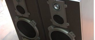
Speaker design
Many people will like the Yamaha NS 6490 Black speakers because they have a majestic appearance. However, there is approximately the same percentage of people who do not welcome such design decisions. Retro style, of course, adds potential buyers, but many opt for more presentable models. But, if we talk about lovers of such styles, we can say that all of them have only positive reviews. Absolutely everyone liked the design. The shape of the speakers is simple and of poor quality. Some owners recognize a slab made from wood chips literally at first sight. But stylization does not only focus on retro performance. Also important was the interesting design of the front surface and the membranes themselves, which are made in silver. The latter are also made of cheap plastic.
Reviews about appearance
The speakers impress with their majestic and massive appearance. Of course, this model cannot be placed in the class of acoustic giants, but their impressiveness gives us hope for high-quality sound. But in terms of appearance, owners are attracted by another quality - the original styling of the Yamaha NS 6490 Retro, reviews of which are generally positive. And this takes into account the fact that there are no special frills in the design. Moreover, the closed-type speakers are implemented in a simple form using cheap material. Many owners of the system, by the way, recognize the walls of the housing as ordinary chipboard. However, the stylization can be seen in a different accent. First of all, in the “piano” design of the front side and silver membranes. Unfortunately, the frame of the latter is also made in a budget version with cheap plastic.
Design
The Yamaha NS 6490 diffusers are of high quality; they are decorated using cellulose. It was also used to cover the speakers themselves. Polymer technology was used on top of cellulose. The latter was also used to create a tweeter membrane. Bookshelf speakers are rich in such equipment. Reviews of the design are harsh and not always positive. For example, there is too much dissonance when feeling the weight (3 kg) and dimensions of the system. This, on the one hand, may seem like a good thing, but on the other hand, the weight was reduced through the use of thin materials and the decision to abandon sound absorption. The speakers received magnetic screens. The heads are of high quality, they are shifted to the right, located on the outer panel.
Sound
The first impression of all owners about the sound of the Yamaha NS 6490 is always deceptive. And it doesn’t matter whether it was negative or positive. Over time, either the shortcomings of sound or its advantages are discovered. Even with the fact that thin and low-quality materials were used, reviews of the speakers and their sound are quite positive. Bass is clear, bright and deep. The dynamics are excellent, you shouldn't expect more from such a system. All instruments are well drawn, both drums and guitars. However, it is better not to listen to classical repertoire on these speakers. Otherwise, you will be disappointed: the sound is too heavy and harsh, especially on the most calm and lyrical parts.
Acoustics indicators
What can you notice right away? The sensitivity of the Yamaha NS 6490 Black is at a high level. This indicator is quite interesting and can be considered as a feature of the model, since not all representatives of the budget class are able to “boast” of such a characteristic – 93.5 dB. She can also explain the good bass. The speakers work great with playing heavy music, which is a plus. The middle and lower sections are also not bad, but not that good either. Sometimes there are flashes of “brightness” of the composition, and distortion may appear. Typically, this occurs in the range from 3 thousand to 6 thousand Hz. Brightness can be controlled by changing the location of the system itself. Excessive flashes of this kind can be easily eliminated if the speakers are positioned at an angle of 45°. Echo and other effects will be heard in the range from 3 thousand to 5 thousand Hz. There is practically no distortion in the bass, and if it does appear, it is quite difficult to notice it. Only a good Yamaha NS 6490 speaker amplifier can cope with the quality of reproduction of resonant ranges.
Acoustic performance
To begin with, it is worth noting the very high level of sensitivity, which not every model in this class can boast of. This characteristic is 93.5 dB, which largely explains the good bass and decent playback of heavy music. The mid-low-frequency section also looks good - however, as the frequency increases, it increases, causing uneven characteristics. Also, against the background of increasing sensitivity in the range of 3000-6000 Hz, a feeling of brightness of playback may occur. It should be noted that the brightness of the Yamaha NS 6490 acoustics can be effectively adjusted by changing the location of the speakers. For example, a 45-degree orientation eliminates unnecessary flash of dynamics. At frequency levels of 3000 and 5000 Hz, specific after-sound effects are observed. As for distortion, there is practically no distortion in the bass - at least for the listener, the impedance is invisible. This also applies to other frequency levels, except for resonant sections - only a high-quality amplifier can cope with them.
Refinement of the device
For its class and price segment, the Yamaha NS 6490 copes well with all tasks. 90% of all buyers say this. Due to the fact that many are confused by the materials used and the fact that they are too thin, most consumers decide to modify their device. Often they only modify the filters, but some prefer a complete change of internals. In order to improve the potential of the purchased speakers, you just need to use certain tips. If you want to get a sound that is as stable, smooth and natural as possible, then you should update the capacitors of the existing filters. By adding damping parts, you can get rid of all the shortcomings that arise when playing the lower parts of the audio range. Consumers are advised to pay attention to 400 V capacitors. You will also need cables for working with the upper and middle frequency ranges, and damping material. Before you go to the store to buy them, you need to note that the update is performed for two columns, so you should calculate the required number of parts. It is also necessary to weigh the pros and cons, because modernization does not always lead to a good result. There are often cases when speakers either completely fail or their reproduction becomes even worse. What can the owner expect? If we talk about good consequences, then there is a minimum of hum at maximum volumes (the damping material gives this effect) and a large amount of bass. Of the bad consequences, you can expect distortion and other unpleasant moments at mid frequencies. If there is no fear of getting such results or they are not important, then you can begin the revision process. You need to start by dismantling the fasteners.
Refinement of columns
Although the speakers cope well with playback tasks for their class, many users are confused by the very simple design of the acoustics. As experts note, you can increase the existing audio potential by simply upgrading the Yamaha NS 6490 system. Refining the filter with upgrading the capacitors should make the sound smoother and more stable, and adding damping material, according to users, eliminates shortcomings in the lower range.
To implement this procedure, you need to purchase 400 V capacitors, a cable for HF and MF, the cross-section of which can be 1.04 mm2, as well as damping material. Accordingly, the calculation should be made to update two columns. But before you start refining, you need to take into account that the effect may be disappointing. For example, improvements as a result of the update include increased bass and the elimination of hum at maximum volume due to damping material. But you should also expect unpleasant distortions in the mid-range. If you are satisfied with this result, then you can begin modifying the AC Yamaha NS 6490. Disassembling the case is carried out traditionally - by dismantling the fasteners. Next, it is necessary to ensure the connection of new elements using tin and silver soldering - this also applies to speaker wires.
Advantages
The Yamaha NS 6490 speaker has its advantages. Reviews about them allow us to say that the system received good data. For example, there are no complaints about the bass; the lower frequencies are just as good. Buyers say that the middle with a stable increase in the range of notes sounds good. Distortion occurs only during sharp transitions. Japanese technology has also distinguished itself by having good power and light weight. Even though the design is too simple and weak, the system easily delivers complex and heavy songs with high quality. Detailing is at an average level.
Reviews about sound quality
Interestingly, the first impression most users have of this model is deceptive. And this applies to both positive and negative listening experiences. But, despite the obviously modest technical implementation of the Yamaha NS 6490 model, reviews of the sound are mostly positive. The acoustics demonstrate the clearest, clearest and deepest bass. The model also maintains good dynamics throughout the entire range. Playing hard rock with popular compositions also evokes positive emotions. Owners of acoustics characterize the sound of such music as hard, bright and emotional. This applies to both drums and electric guitar.
The situation with the classical repertoire is not so clear. In this case, high-frequency spectral information is distinguished by hard shades, which often interfere with soft and calm parts. It is often observed that the dynamic resource of the Yamaha NS 6490 speakers is turned on, which saves the situation a little. In general, users note that these are bright and powerful acoustics, the capabilities of which are sufficient to fill rooms of up to 60 m2 with sound.
Flaws
The Yamaha NS 6490 speaker system, like any other, has its drawbacks. Which ones are the owners talking about? The case has too thin walls, the “inside” is quite poor, since there is no insulation and other important elements. In addition, cheap materials do not promise a long service life. However, what is important is that for some reason the listed shortcomings do not affect the sound quality. Rather, this places the representative in the budget segment, since it cannot claim to be in the best class with similar characteristics. Some consumers also criticize the playback quality. For example, owners lack bass. Often modifications are made precisely to improve the reproduction of low frequencies.
Model cost
The manufacturer managed to achieve a very difficult task - to offer mid-level speakers that will cost the same as budget equipment. The price tag of the model varies from 10 to 12 thousand rubles, which is very attractive for a device with such characteristics. Of course, there are similar options in competitors’ lines, but they are inferior to the Japanese model in terms of sound. In turn, the Yamaha NS 6490 acoustics offer good musical abilities, while having a body and components of low quality. It was the savings on components that made it possible to produce such a cheap model.
Price category
The manufacturer was able to offer consumers equipment of average quality for little money. In fact, the speakers are included in the budget segment. Basically, the price for them does not exceed 12 thousand rubles. This greatly attracts potential buyers. Of course, among competitors there are similar models that can compare with the proposed technology. However, they still lose a little in sound. The Yamaha NS 6490 speakers, a review of which will help you decide on your choice, offer the owner generally good sound, but at the same time a low-quality body and an undignified design. It is due to such savings that the manufacturer was able to reduce the cost.
Benefits of speakers
The system initially provides a good music scene. There are practically no complaints about the bass and the lower level of the frequency-amplitude range. The middle also sounds good with rising notes, although slight distortion is observed during transitions. Also, the advantages of three-way Japanese speakers include the combination of low weight and power. Despite the weak design, the acoustics pull out even complex compositions, while providing a certain level of detail.
What are the speakers suitable for?
Reading reviews on the Internet and listening to customer stories, we can conclude that the device is most often used with audio systems from the budget segment, which do not have anything outstanding. If you make a small modification to the speakers manually, you can achieve better playback results, but we are not talking about something powerful and amazing. Rock and other popular genres are most suitable. They are the ones that sound great from the “mouth” of the Yamaha NS 6490. A subwoofer is what these speakers can serve as. Of course, only within the existing characteristics. Many car enthusiasts notice that the device has a good theatrical front. In general, it is best to use speakers either with products from this manufacturer, or with those that are in the same price segment.
Results
If the speakers have a high-quality amplifier, then many buyers will like the playback of the device. Even with the fact that sound bars that are distinguished by their compact sizes are gradually becoming more popular, the Yamaha NS 6490 bookshelf speakers still remain in demand. Most often, they appeal to those who prefer to receive surround sound and the “picture” as a whole. Demand remains stable to this day due to the good price tag, which goes well with the characteristics. Of course, all the shortcomings are obvious and a certain proportion of consumers refuse to buy these speakers because of them, but still, they are easy to come to terms with. They are not as serious as they might seem at first glance. The design is not very attractive, the materials used are of poor quality, but all this is hidden under the retro style.