↑ Original S-30 diagram
In one pair of speakers, instead of a block of factory inductors, I made a similar one of my own - using a low-frequency coil with a thicker wire: f1.3, observing approximately the same design of the triple coil, location on the “trough”. I glued the high-frequency coil through a 10-mm spacer onto the low-frequency coil so that it would be like in the original filter, I adjusted the low-frequency coil to the original filter (LLF = 0.394.0.398 mH before the tap and LLF = 0.48 mH with the tap (from the tap approximately 12...14 turns), LHF = 0.28...0.297 mH, f0.72 mm - these are the measurements that gave me four “native” filters from 1983). True, my winding diameter and length were larger - 35 mm and 40 mm at HF and LF.
I made the board myself, of course, without an indication, and placed it on a removable cover, just like in the original board. But due to the increased size of the coils, they are located closer to the woofer. There were doubts that this would greatly disrupt the setting. The capacitances were: in the low-frequency notch: 1.98-1.99 µF; R-C chain at LF: 7.3 ohm + 8.0 µF; on the HF I used paired MBMs: input - 1.98 µF and 2.09 µF - this is for the speaker). If you have a good inductance meter and winding wire, this is not difficult. Inductances and capacitances in pairs are similar with an accuracy of 1-2%.
Weconic EQB-105 power amplifier review
This is what this amplifier looked like, although I got it without the side ears, which are used to attach the amplifier to the internal chassis of the car.
Rice. 1. Appearance of the Weconic EQB-105 power amplifier with a 7-band equalizer.
, a company owned by Inter-Union Techno GmbH, 76829 Landau (inter-union.de). She was engaged in the manufacture of various automotive audio equipment: acoustic systems (AS), power amplifiers, equalizers.
The Weconic brand has already become a thing of the past, leaving behind a set of various audio devices, one of which fell into my hands.
Amplifier characteristics:
- 4 outputs for connecting speaker systems;
- 2 signal inputs;
- Output power indicator of 5 multi-colored LEDs;
- Graphic equalizer with 7 bands;
- Balance regulator between each pair of speakers;
- Power supply - 12-14V.
I remember the first time I saw the inscription on the amplifier “100 Watt Live Sound” - I just couldn’t wait to connect it to my Amphiton 100AC-022, then I realized that this value was exaggerated. It was assumed that the amplifier produces 4x25W, but in reality you can get about 17W per channel provided there is good power supply.
↑ Main directions of improvement of the S-30
↑ S-30 has no bass
This is true, however, you can improve the sound by choosing a 10GD34 - with fs<70 Hz, and pasting the walls with felt, choosing the length of the FI - if the FI is crumbling from foam rubber, “strengthen” the FI with an internal plastic insert with an internal diameter of 30 mm - jars from containers are well suited for any photographic films - you cut off the bottom - and you have a ready-made frame/extension for the FI.) 10-15mm felt, glued to all internal walls except the front, significantly improves the sound - after this the midbass does not wheeze even at 30W of power, but you can burn out the speakers.
↑ Tall ones “creep”
It can be improved by installing older HF 3GD-2 with silk domes (1979–1983) and selecting a notch parallel to the HF 3GD2 - with frez = fres HF, for example: CLR: L = 0.4 mH, C = 6, 5 mk, R = 6.8 Om for fres HF = 3121 Hz, as well as using other types of HF capacitors - namely MBM, 2 × 1.0 μF x 160 V. It is not advisable to increase the capacitance in the notch to more than 6.5 microfarads - it is better to play with inductance to adjust the circuit. You may have to adjust the division coefficient in the resistive divider at the HF (in the “native” HF filter, the trimmer sliders are in the middle: 33 ohms / per 2 = 16 ohms, i.e. the HF signal was divided approximately in half).
MBM capacitors produce a very bright sound, although we must remember their limited variable capabilities (160V x 5% = ~8V). The notch almost eliminates the hissing and tutting at the HF resonant frequency, but limiting it with a 6.8 ohm resistor is necessary so that the desired after-sound of strings and cymbals remains. The capacitor in the notch is K73-17, the inductance L = 0.31.0.45 mH is wound with PEL-1 wire f 0.72 mm. Resistor 6.8 ohm - accurate, +/- 1%, 2 watts, type C2-13.
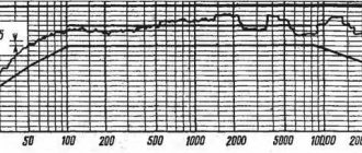
↑ Result of measuring filter inductances
The middle is a bit cloudy. Yes, it's hard to get rid of!
↑ Speaker output and resolution are low
Yes it is. But, you can experiment carefully: add a countermagnet of the required size to the 10GD34 and use a trimmer to reduce the coefficient of the resistive divider at HF, having previously noted the initial position of the trimmer so that you can return to the original state of the filters. All this will increase the mid-high frequency output and the overall dynamic range. The anti-magnets in one pair are glued slightly different - I selected them to equalize the output of both speakers in the midrange.
↑ High level of distortion
Yes, there is such a thing, and it’s unlikely to be cured. I tried to cover the front panel from the inside with plasticine - the sound disappeared - I had to put everything back!
↑News
The use of MBM on HF gives a much more interesting sound than MBGO, but you need to take it before 1991, and, better, Moscow MBM 1.0uF x 160V - Azerbaijani ones - are bad.
The homemade filter does not have a resistive divider after LHF - a tap to the 2.09 µF capacitance of the low-frequency rejector and speaker; further - 132 ohms to ground, parallel to LHF. Selected from MLT-2.
The wires inside went to the HF - from SVEN and to the LF - acoustic - 1.0 mm², with a blue inscription from YOTA. As it turned out, the wires sounded very good.
Oddly enough, this filter option produced a better sound than the original S-30 filter. Below is the result of measuring the filter inductances. The measurements were carried out with a digital L-meter adjusted for reference inductances that I have had for about 20 years.
According to my measurements, the real inductance is less than that indicated in the diagram, this is explained by the fact that in a real speaker it reaches the circuit one due to the relationship between the coils and the proximity to the woofer magnet.
Instead of an introduction
While going through old/non-working electronics in my closet, I came across a small, but no longer working Weconic EQB-105 car power amplifier. Before I assembled my homemade Phoenix P-400 UMZCH, this little guy rocked all my speaker systems and pleased me with a fairly good sound. Later, this amplifier burned out because it was supplied with a slightly too high supply voltage and driven to full power.
There were still non-working Radiotehnika S-30 acoustic speakers, I thought: “if they were repaired and combined with an amplifier, they would make excellent acoustics for a home TV”!
I didn’t want to buy a set of TV speakers for $150+, but here I had the opportunity to put together a budget Hi-FI audio system by investing a little of my time and quite a bit of money.
So, I’ll start my story with the amplifier...
↑ Summary
The sound has improved - this was expressed in a noticeably more solid bass and, coupled with the anti-magnet on the 10GD34 and “raised” high frequencies - in a certain, I would say, fundamentality of the resulting sound. This is not only my personal opinion, but also that of everyone who listened to both versions of the filter (on the same speakers with speakers), including my wife, the most unbiased listener (oh, these wives of ours - how they don’t like our hobby, tearing off, their words, us from them!). The factory filter sounded collected, correct, but somehow “near” the speakers. The homemade sound came out of the speakers and was above the speakers, EVERYWHERE.
Amplifier repair
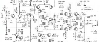
The power amplifier is made using a bridge circuit using two HA13001 microcircuits. The preamplifier is assembled on four op-amps, which are contained in one BA10324 chip, the equalizer filters are assembled on 14 transistors, and the output power indicator is on the LB1403 chip.
Having completely disassembled the amplifier, I realized that there was a little more work to be done than expected.
Rice. 2. Weconic EQB-105 amplifier disassembled, only electronics (picture clickable).
What you have to do:
- Replace the HA13001 chip;
- Replace burnt out backlight bulbs;
- Clear everything of debris.
Although the amplifier had 4 outputs, it actually has 2 power amplification channels, and the power distribution between the four channels is done using a dual ceramic variable resistor. The handle of this resistor is combined with a switch that allows you to connect the signal source through the amplifier (pressed, the amplifier is on), or directly to the speakers (pressed).
One of the HA13001 microcircuits in the amplifier burned out. As it turned out, this is a rather rare microcircuit from Hitachi Semiconductor.
Rice. 3. Chip Hitachi HA13001 (Japan).
Searches for this microcircuit in online stores did not yield results; a trip to radio points on the market was also unsuccessful. One of the old-time radio amateurs at the bazaar told me that Hitachi ULF microcircuits were very difficult to counterfeit, so they were valued.
In one of the local electronic components stores, I still managed to find two HA13001 microcircuits, although one had a broken leg - I took both at a discount! Then I found HA13001 chips on AliExpress.
Characteristics of HA13001:
- Output power, stereo - 2 x 5.5 W;
- Output power, bridge - 17.5 W;
- Supply voltage, min. — 8 V;
- Supply voltage, typ. - 13.2 V;
- Supply voltage, max. — 18 V;
- Quiescent current - 80mA;
- Reproducible frequency range - 20-20000Hz;
- Maximum output current - 4.5A;
- Gain - 50 dB.
Rice. 4. Schematic diagram of a two-channel and bridge power amplifier on the HA13001.
Replacing the microcircuit immediately produced results - both channels began to sing, but for some reason one of them played an order of magnitude quieter. I was already a little upset, but then Mr. “chance” came to the rescue.
Guests came into my room with a baby, who immediately became interested in what was playing and even glowing. Taking the baby away from the working amplifier, I lifted the board a little - both channels started playing smoothly for a second.
Apparently there is no contact somewhere: bad soldering, a torn conductor, a damaged part, a crack on the board? — the cause had to be found out and eliminated.
Having felt all the details and conductors, I did not hear any changes in the sound. Turning on the desk lamp and armed with a magnifying glass, I began a thorough inspection of the printed circuit board and electronic components for any visible defects. All the parts are intact, I only soldered some connections, but I still couldn’t find the location of the missing contact.
I really didn’t want to, but I still had to unsolder the board with the regulators and look for the reason on it. Getinaks printed circuit boards are very delicate - if you overheat the contact a little with a soldering iron, any trace can easily fall off.
Rice. 5. Sealed equalizer board with regulators (picture clickable).
As expected, several tracks fell off - no problem, then we’ll replace them with heat-resistant conductors and everything will be OK.
I soldered the suspicious connections on the regulator board, and since the board was sealed off and there was easy access to the components, I decided to replace all the control panel backlight bulbs at the same time.
A quick measurement of the current consumed by one light bulb showed me a value of 34mA. And if all 4 light bulbs are on - approximately 140mA of current to nowhere, 12V * 0.14A = 1.68W!
Rice. 6. Measuring the current consumed by an incandescent lamp to illuminate the panel.
I decided to replace incandescent light bulbs with blue LEDs, which turned out to be very economical. I connected one LED through a 10 kOhm variable resistor to a +12V power source, turning the resistor knob I achieved a fairly bright glow at a current of only 4 mA. Having measured the resistance of the resistor in a fixed state, I got a value of 2.5 kOhm.
Result: 4×4mA=16mA (versus 140mA) + pleasant blue glow. ))
As it turned out, it won’t be possible to simply install LEDs - their diameter is 5 mm versus the diameter of the light bulbs 3.5 mm. The solution here is simple - adjust the dimensions of the housing of each LED using a needle file (file).
Rice. 7. Adjusting the size of LEDs using a diamond file (clickable).
I soldered the LEDs in place of the incandescent lamps, and connected 2.5 kOhm quenching resistors in series to each LED with a surface-mounted mounting on the back side of the board, having previously cut the tracks so that each pair of LED + resistor was connected in parallel.
Rice. 8. Soldered LEDs with quenching resistors.
Rice. 9. LED glow test for the backlight panel.
The brightness of the light is excellent; then all that remains is to solder an LED to illuminate the volume control area. We've sorted out the backlight, let's return to the problem with the skew in the volume of the channels.
Having soldered the board with tone controls to the main one and connected the amplifier to the power supply, I was convinced that the problem had not disappeared, now no deformation of the board or its bending affected the operation of the amplifier in a positive direction.
I unsoldered the front panel board back, decided to connect both boards with flexible conductors and then look for the cause of the problem in this form. This had to be done right away, but I hoped that the problem lay in the solder joints of both boards - as it turned out later - almost so, but not quite.
Rice. 10. Temporary connection of boards using flexible conductors.
After playing a little with these scarves, rotating them, squeezing them and feeling the details, the reason for the distortion in the sound of the channels was found. It was hidden in a cracked path near the hole-groove for inserting part of the main board.
It was not possible to notice this crack by visual inspection - it was hidden under a thin layer of rosin. I began to unsolder one by one all the conductors connecting both boards and analyze them. Having unsoldered one of the outer conductors, I noticed that this did not affect the operation of the amplifier in any way - strange. Having cleared the track to which this conductor was soldered of debris, I immediately noticed a defect - HURRAY!
Rice. 11. The reason for the distortion in the sound of the amplifier channels is a crack in the track (clickable).
The cracked track was cleaned and soldered. To connect the contacts in places where the tracks disappeared, I decided to use a heat-resistant wire with fluoroplastic insulation - MGTF.
Rice. 12. We restore the tracks by connecting the contacts with heat-resistant MGTF wire.
After restoring the tracks and connecting the boards, all that remains is to remove all debris on the variable resistors, clean the case and controls from dust. To do this, I used a piece of cotton wool soaked in alcohol and wound around a cleaned match.
Rice. 13. Cleaning the amplifier case and components from dust and debris.
Rice. 14. Refurbished Weconic EQB-105 amplifier.
Connecting speakers and power amplifier
To power the Weconic EQB-105 power amplifier, a small switching power supply (PS) from some computer peripheral was found. At the output, the power supply produces 12V at a current of up to 3A, which is quite enough to power this amplifier and produce about 2x15W at the output.
To connect the power supply to the amplifier, I found an old high-frequency coaxial connector, the kind used in old Ethernet computer networks based on coaxial cables. What I found, I applied. )
Rice. 52. Power supply for the amplifier.
I connected a holder with a 4A fuse into the gap in the positive power supply conductor of the amplifier, just in case. )
Rice. 53. Amplifier power connector with fuse.
I thought about putting heat shrink on the part of the connector that goes to the amplifier, but there was no suitable diameter in stock, so I simply insulated it and tied everything together with nylon thread - it turned out quite neatly and reliably.
Rice. 54. We isolate the connection of the conductors and the connector using a thread.
Since the amplifier has four independent (not pressed to ground) conductors for supplying a signal to each of the channels, I decided to do this: I connected one conductor from each input together and connected it to the power supply negative.
As a signal cable, I found a piece of shielded cable from some device with a USB connection, about 1.5 m long. The cable contains 4 cores in a dense screen with a binding of conductors.
I connected the two wires of the cable to each other and connected them together with the screen to the ground (minus) of the amplifier. I used the remaining two free wires in the cable as signal wires for the right and left amplification channels.
Rice. 55. Connecting the amplifier inputs to the signal cable.
The Mini-Jack 3.5 connector was removed from non-working headphones. Soldering it to the signal cable was not difficult; the common conductor connected to the screen was covered with heat shrink. The connector at the junction was tightly and under tension wrapped with thread.
Rice. 56. Connecting the Mini-Jack 3.5 connector.
To connect the speaker to the amplifier I used a two-core audio cable. I cleaned the ends of the cable that will go to the terminals of the speaker systems by about 15mm and completely tinned them, and left the ends that will go to connect to the amplifier longer - about 40mm and tinned them only at the end so that the conductors do not unravel.
Rice. 57. Preparing conductors for connecting speakers to an amplifier.
The result of the work carried out can be seen and listened to in the short video below:
Composition playing in the demo: John Petrucci - Glasgow Kiss.
Repair of flexible flagella leading to speaker diffusers
Having freed up space on the desktop and putting the speaker housings aside, I set about repairing the 10GD-34-80 speakers. A very common cause of speaker failure in Soviet-made speakers is a fracture of the flexible braided cords running from the contact block to the diffuser, which leads to loss of contact with the magnetic system coil.
Rice. 22. The reason for the inoperability of the speaker 10GD-34-80 is a flexible flagellum broken off from the diffuser (clickable picture).
When starting repairs, in addition to a soldering iron with a thin tip, you will need: wire cutters, a small screwdriver, tweezers and a thin scalpel. If you don’t have a scalpel, you can make a small homemade cutter from a metal saw blade by sharpening it on a sharpening machine.
Rice. 23. Necessary tools for repairing flexible flagella.
The flagella going to the diffuser were sealed off from the speaker contact blocks, and the insulating rubber tubes - cambrics - were also removed.
Rice. 24. Unsolder the flagella from the contact columns in the 10GD-34-80 speaker.
Rice. 25. Remove the end of the contact flagellum with the insulating tube.
Very carefully, slowly, I bent the two antennae to the sides, which press the flagellum of conductors to the diffuser. To do this, you can use a scalpel or a small screwdriver with a thin tip.
Rice. 26. Unbend the antennae that hold the electrically conductive flagellum on the speaker diffuser (clickable).
After this procedure, it is very important not to move the flagellum or tug on it, since it is no longer secured and a conductor from the coil of the speaker’s magnetic system is soldered to it.
Using a soldering iron with a thin tip, the flagellum was sealed off from the coil conductor. If a soldering iron with a thin tip is not available, then you can make a temporary thin tip by winding a thick (3-5 mm cross-section) copper conductor, cleared of enamel, onto a thick soldering iron tip, followed by sharpening the wound tip using a file.
Rice. 27. The damaged flexible conductor was removed from the speaker, the thread remained and the wire mesh was broken.
Having unsoldered all four flagella (for 2 speakers), I began to look for a donor for new flagella - flexible conductors going to the diffuser.
An excellent donor can be the conductors from the cable that connects the handsets to the base - they are twisted into a spiral and are very flexible, resistant to repeated bending. Finding such a conductor will not be difficult at the bazaar, or by visiting local telephone operators.
Rice. 28. A cable from a telephone handset is a donor for making flexible flagella.
Rice. 29. Structure of a flexible telephone cable (click on the picture to enlarge).
A telephone cable consists of three cores, each of which is a conductor in multi-colored insulation, which in turn consists of six cores, and each core is an electrically conductive foil wound on a fibrous base (thread).
The cable insulation was carefully cut along the entire required length, all three conductors were removed and cleaned of insulation. The length of the donor conductors required to repair two speakers is approximately 35 cm.
Rice. 30. Flexible conductors removed from the cable from the telephone handset.
At first I thought of just twisting two or three sets of conductors into one, but a more sensible idea came to mind - weave all three sets of conductors into a braid!
Rice. 31. We braid a pigtail from flexible telephone conductors for repairing Radiotehnika S30 speakers (click on the picture to enlarge).
A few minutes of magic, with the help of dexterous fingers, and the braid of three sets of six conductors is ready!
Rice. 32. Finished braid of 18 flexible conductors (3 sets of 6 pieces).
The flagellum turned out to be a little thicker than the original one, and it is also much more flexible than the previous one, it will be an excellent replacement!
The length of the braided braid was divided into four even parts, each approximately 8 cm long (with a margin). The length of the original flagella is approximately 6-7 cm.
Rice. 33. We measure the length of the original flagella from the woofer from the Radiotehnika S30 column.
One of the ends of the cut pigtail was well tinned with lactic acid, thus all 18 conductors were soldered together.
If there is no lactic acid, then rosin will do; in this case, you may have to pre-clean the conductors before tinning.
Rice. 34. Tinned end of a pigtail (harness) made of flexible conductors from a telephone.
An extra piece of the harness (not tinned, on the left) was bitten off using wire cutters and placed between the tendrils on the speaker diffuser. For ease of installation, the speaker can be slightly raised by placing an unnecessary book or other object about 4-5 cm high under it.
Rice. 35. The flexible flagellum is attached to the diffuser using through metal tendrils (click to enlarge).
After the antennae were carefully bent, the speaker was slightly raised. Using a small piece of hard material on the back side of the antenna mount, I pressed well on the place where the harness was attached to securely fasten it between the antennae. After this, the tinned end of the flagellum was soldered to the terminal of the coil of the speaker’s magnetic system.
The joint can be slightly filled with rosin or a small amount of glue, for example the Globus brand, can be applied to it.
The second end of the harness was threaded through the hole in the contact block, after which a sufficient length was selected and the excess end was bitten off using wire cutters.
The length of the flagellum and its fastening should be such that it bends freely and without tension when the diffuser moves in different directions, but does not touch the diffuser itself. When selecting the length of the harness, you can move the diffuser a little in different directions and see that everything is in the best possible shape.
An insulating tube was put on the remaining end of the flagellum and it was soldered to the block, having previously laid the tube in a special cutout in the speaker body.
Rice. 36. A flexible homemade harness is soldered to the diffuser and speaker block of Radiotehnika S-30.
When I removed one of these tubes, it literally crumbled from old age, so I replaced it with heat shrink of the same length, taking a obviously slightly larger diameter and using a heated soldering iron, pulled it together on a bundle to the desired condition.
Rice. 37. We use heat shrink instead of a damaged insulating tube when repairing a speaker.
The mounting points for the antennae on the diffuser, on the opposite side, were secured using fusible silicone; glue could also be used.
Rice. 38. We fix the attachment points of the holders for the electrically conductive harness.
In this way, all the flexible harnesses in each of the speakers were replaced.
Correcting deformation of protective nets
The protective grilles of both woofers are slightly dented in the middle. It is very difficult to align them with your fingers just like that - correcting a deflection in one place of the mesh will result in deformation in another.
Rice. 44. Deformed grids from Radiotehnika S-30 woofers.
As a basis for leveling, you can use some kind of small, solid, spherical object or the round protrusion of an old wooden chair.
I took a simple wine rind, installed it vertically, put a mesh on it and, resting my palms on it, easily aligned all the deformed places on the mesh.
Rice. 45. Restored grids for Radiotehnika S-30 woofers.
Replacing tubes for bass reflexes
To replace bass reflex tubes made of foam rubber, you can choose a variety of materials. If you need harder bass, then you can use PVC tubes, and if the bass needs to be soft, then we use fiber material.
I used a strip of artificial synthetic fiber, which turned out to be quite dense and from it it is quite possible to roll up a tube for a bass reflex.
Rice. 39. A skein of artificial synthetic fiber.
When disassembling the acoustic speakers, the approximate length of the bass reflex tube was measured - 5 cm, so I cut a strip of exactly this height. The length of the strip was approximately 40cm.
Rice. 40. Cut a strip of material to make a bass reflex tube.
Then this strip was twisted around the bass reflex protrusion on the speaker cover so as to form a tube. The places where the strip begins and ends were fixed with fusible silicone.
Rice. 41. We wind a synthetic pipe for the bass reflex and fix the ends of the strip with silicone.
To ensure that the front cover fits tightly to the wooden box of the speaker, two round gaskets were cut from the same synthetic material in the place where the hole was made for the bass reflex. Essentially, we got two donuts, each with an outer diameter of 85mm and an inner hole of 35mm.
Rice. 42. Rings for tightly pressing the tube to the body and column cover.
The rings at several opposite points were impregnated with fusible silicone and glued together, then with the same silicone they were glued to the previously prepared tube. For reliability, the tube was additionally wrapped with nylon thread.
Rice. 43. Finished bass reflex tube for Radiotehnika S-30 loudspeakers.
As a result, two such bass reflex tubes for speakers were manufactured.