Today, audio equipment, like computers, belongs to a popular category of goods. Look around - almost every second person walks around with headphones in their ears and smartphones in their hands. Many people buy home theaters with powerful acoustics. Technology offers are constantly being updated, so many people want to buy a tablet, phone or e-reader of a more advanced model, but high prices do not always allow this.
Design Features
The speaker body is made in the form of a rectangular non-collapsible box made of chipboard veneered with valuable wood veneer. The thickness of the case walls is 18 mm; the front panel, in order to increase its rigidity, is made of a 38 mm thick plate. The design of the case includes elements that increase the rigidity of the case and reduce the amplitude of vibrations of the walls, in particular, there is a wooden spacer that connects the front panel and the rear wall and is located between the low-frequency head and the bass reflex hole.
Description
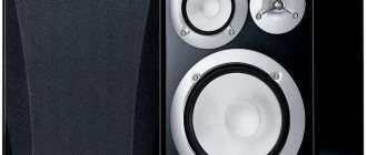
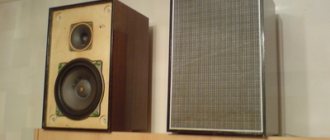
Amphiton 35AS-018 is a three-way speaker system with a bass reflex. They were produced at the VEMZ in Volzhsk and at the Karpaty Production Association in Ivano-Frankovsk.
Designed for high-quality reproduction of music and speech programs in stationary living conditions. The recommended power of a high-quality household amplifier is 70 W. The preferred installation option is floor-mounted. The speaker body is made in the form of a rectangular non-demountable box made of chipboard 16 mm thick. The front panel, in order to increase its rigidity, is made of a combination of multi-layer plywood and chipboard, with a total thickness of 22 mm. The entire body is finished with dark gray synthetic film. The housing design includes elements that increase its rigidity and reduce the amplitude of wall vibrations. Each of the heads is framed by decorative black plates made from stamped aluminum sheet, with four mounting holes; Each head is protected at the front by a metal perforated mesh. The midrange head is isolated on the inside from the total volume of the housing by a special plastic casing. Inside the housing, on a special chassis, there are electrical filters that provide electrical separation of the speaker bands. On the rear wall of the case there are knobs for adjusting the sound pressure level in the midrange and treble.
The speakers use the following heads: — LF 75GDN-3; — SCH 20GDS-1-8; — HF 6GDV-1-16; Specifications:
— Reproducible frequency range — 25-25000 Hz; — Uneven frequency response of sound pressure, at the lower limit frequency of the range relative to the level of average sound pressure — 18 dB; — Uneven frequency response of sound pressure, in the range of 100-8000 Hz — +-4 dB; — Level of characteristic sensitivity — 85 dB; — Nominal electrical resistance — 4 Ohms; — The minimum value of total electrical resistance is 3.5 Ohms; — Maximum rated power — 90 W;
Size: 670x272x370 mm; Weight: 23.5 kg.
Installed speakers:
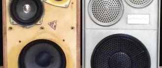
A set of heads was used similar to that used in 35 AS-012 (PO Radiotekhnika): 75GDN-3 , 20GDS-3 , 6GDV-7 , manufactured by PRZ Ivano-Frankivsk. The heads are installed on the front panel of the housing symmetrically relative to the vertical axis of the speaker. The heads are framed with decorative overlays made of plastic with a metal-like coating: the woofer head overlay is ring-shaped with four fastening protrusions in the form of “ears”, the midrange and treble head overlays are rectangular. To prevent the influence of air vibrations in the speaker housing that occur during operation of the low-frequency head on the characteristics of the midrange head, the midrange head is isolated on the inside from the total volume with a special sealed plastic cap.
On the front panel of the speaker, in addition to the heads with pads, there is a hole with a diameter of 70 mm - the output of a plastic bass reflex pipe, 180 mm long, as well as a decorative nameplate with the name of the speaker, the main technical characteristics and a curve approximately depicting the frequency response of the sound pressure of the speaker. The bass and midrange heads at the front are protected from external mechanical influences by a blackened metal mesh. The geometric dimensions of the bass reflex provide tuning to a frequency of 25 - 30 Hz.
Internal volume 63 l. To reduce the influence of sound pressure on the frequency response and improve the sound quality of the loudspeaker resonances of the internal volume of the housing, the latter is filled with a sound absorber, which is mats of technical wool, covered with gauze, evenly spaced and fixed to the internal walls of the housing.
Filter circuit 35AC-018:
L1 = 1.4 mH, L2 = 1 mH, L3 = 0.43 mH
Isolation filters are mounted inside the housing on a single steel chassis, providing electrical separation of low-, mid- and high-frequency speaker bands. Each of them represents:
- low-frequency head filter; high-pass filter of the first order, provides a frequency response decline of 6 dB per octave;
- filter of the mid-frequency head - a first-order bandpass filter, provides a decrease in the frequency response towards low and high frequencies of 6 dB per octave;
- The high-frequency head filter is a second-order low-pass filter that provides a decrease in the frequency response towards mid-frequencies of 12 dB per octave.
Crossover frequencies: between the LF and MF heads - 650 Hz, between the MF and HF heads - 4500 Hz. The design of electrical filters uses C5-35 type resistors, MBGO capacitors, and inductors on plastic frames with “air” cores.
On the back wall of the speaker housing there are special terminals that allow you to connect the supply wires using a screw connection. The connection polarity is marked on the AC terminals. There are four plastic feet installed on the base of the speaker. The delivery set includes a specially shaped stand made of nickel-plated steel rod, which allows, if necessary, to change the angle of inclination of the acoustic axis of the speaker.
Thanks to Fedor, as well as to the Snake Fire workshop for the photo.
Modification of filter 35 AC-018 with original speakers (Nivaga)
Description of the acoustic system 35 AS-018 “Amfiton”
Part I
In its original form, this opus of Soviet industry sounds powerful, but inexpressive. Only on individual compositions is it possible to capture a stereo panorama and approximately localize apparent sound sources (AS). With the advent of DVD and home theater, I wanted to improve the spatial parameters of the system. I began to see what people thought about this. The proposals on the site come down mainly to replacing the mid-range speaker. I figured it would be expensive and troublesome. I began to analyze the filter circuit in terms of mid and high frequencies. I discovered that only 20% of the supplied energy goes to the midrange. Why should he sing, if the total reactance of C1 and L2 (according to the original circuit) is approximately 33 Ohms in the range from 500 to 5000 Hz and keeps the poor fellow on a starvation diet. We had to increase the capacitance of capacitor C1 to 40 μF, reduce the inductance of inductor L2 to 0.43 mH and combine it with L3 in order to provide the midrange with energy at a level of about 50% of the input, i.e. 2.5 times more than the original. And he started singing! And how he sang! Stereo panorama across the entire room, and not just along the axis between the speakers, clear localization of the KIZ, the effect of presence, even some kind of volumetricity. All the old, long-known compositions sounded new, the musical fabric became so subtle and ornate. The resulting diagram is shown in Fig. 1.
Rice. 1. Filter circuit for loudspeaker 35AC-018. Stage 1
I tried to use all the native elements of the original filter. Additionally, I had to purchase a capacitor C1.1 with a capacity of 30 uF and install it in place of the removed L2 (according to the original scheme), for which I had to drill 2 holes d3.3 in the crossover chassis and cut an M4 thread. Everything else is done with a soldering iron and tweezers. Along the way, I increased the cross-section of the wires through which the low-frequency link current runs to 1 mm2 and corrected the circuit error: I tore off resistor R2 from L3 (in my opinion, this was a copyist’s mistake) and installed it parallel to the high-frequency speaker - its presence there is logical and justified.
And may the acoustics gurus forgive me, but I did not find any use in the Zobel link, either in the low-frequency section or in the mid-frequency section. Maybe I'm wrong, but in my speakers I short-circuited resistors R3, R4 and R1, which is shown in the dotted line in the diagram. Whoever believes - let him leave it, whoever doubts - let him check, fortunately, through the bass reflex pipe, you can bring out the switches and click them.
25.05.2009
Part II
When I wrote that as a result of the modification, “the midrange began to sing and then began to sing,” I was lying a little. For he did not sing alone, but together with the high-frequency driver, and synchronously and in phase, which none of the filters known to me for three-way speaker systems can yet provide. And in a pair, the speakers operate in the most sensitive range for the human ear, 3–6 kHz, where the slightest distortion torments the hearing. The spectrum of most musical instruments and the overtones of the human voice are also located here. Therefore, the synchronism and in-phase operation of the speakers is very important here, which is ensured automatically when both filter elements are loaded.
Now let's think and move on. At high frequencies, capacitors C2 and C5 (Fig. 1. in Part I ) actually work in parallel, but with a slight phase shift created by C1 + C1.1. Following the proposed interaction mechanism, it becomes clear that capacitor C2 is no longer needed. Its functions may well be performed by C5, since the effect of C1+C1.1 at high frequencies is negligible.
Now about docking with the low-frequency link. In order to more accurately match the low-frequency filter (120 μF x 4 Ohm = 480 ms) and the midrange + high-pass filter, it is necessary to bring their time constants closer together, for which we had to increase the capacitance of the capacitor C1 + C1.1 to 60 μF (60 μF x 8 Ohm = 480 ms).
The resulting diagram is shown in Fig. 2. It is already significantly different from the original:
Rice. 2. Filter circuit 35AC-018. Stage 2
I prefer to short-circuit resistors R3, R4, but this is not necessary. During the discussion, it turned out that many replaced Soviet-made midrange and high-frequency speakers in their speakers with imported Visaton ones, and based on this they argued that my modification was not suitable for them. Why? Fits! Especially for this case, the circuits in Fig. 3 and Fig. 4 have been developed.
Rice. 3. Filter circuit 35AC-018. Stage 2.1
In version Fig. 3, the inductance of inductor L3 remains unchanged, but the crossover frequency between the midrange and high-frequency speakers is about 3.5 kHz, which leads to an increase in the load on the high-frequency speaker.
Rice. 4. Filter circuit 35AC-018. Stage 2.2
In version Fig. 4, the inductance of inductor L3 is reduced to 0.27 mH by winding 20 turns, and capacitor C5.1 is removed. The crossover frequency between the midrange and tweeters approaches 5 kHz. I'd prefer this one.
In all variants of circuits, the range of reproduced frequencies of the midrange speaker is limited by the filter parameters, which eliminates the individual characteristics of different models. The only difference is the volume (sensitivity), to which the low-frequency and high-frequency parts of the loudspeaker have to be adjusted. Therefore, I am not a supporter of changing speakers in speakers without special need.
Both professionals and amateurs involved in improving acoustic systems mainly chase the linearity of the frequency response, missing out on other parameters. I decided to chase the stereo effect, volume, panorama, even to the detriment of the linearity of the frequency response.
As you know, thought does not stand still. The idea of obtaining a diffuse sound field over the entire range of reproduced frequencies is looking for new solutions. But more on that next time.
08.07.2009
Part III
Six months have passed since the publication of the previous parts. The people actively read, but did nothing. Just in January, one of the readers tried to redo one column. I seemed to like it. He promised to give a full review after remaking both speakers and disappeared. Apparently, when listening to the set, my mouth opened in surprise, but couldn’t close it. Well, God bless him, let him rejoice. At the end of the last article, I promised to continue the story about improvements to the filter. After a certain optimization stage, you can publish the resulting solution. To understand the process of filter conversion, let’s redraw the diagram in Fig. 2 from Part II in the form presented in Fig. 5.
Rice. 5. Diagram of an alternative filter 35AC-018. Stage 3.1
This is the same circuit, only with the order of connecting the midrange + high-frequency section inverted. In this case, all speakers are connected in phase. The sound of speakers with this circuit is no different from the original ones assembled according to the circuit in Fig. 2.
Analysis of the resulting circuit shows that capacitor C1+C1.1 is, in general, superfluous. Its functions at medium and high frequencies can easily be performed by a battery of capacitors C2-C5. But choke L1 will greatly bypass the midrange + high-frequency link. So its inductance can be increased. In this case, the crossover frequency between the bass and midrange sections will decrease, but will not go beyond the range of the midrange speaker, and the range of the woofer will narrow to that of the subwoofer. The resulting diagram is presented in Fig. 6. All capacitors and resistors are taken from the original filter. A choke with an inductance of 0.3 mH is obtained from the original one of 0.43 mH by winding 16 turns from it. With a choke with an inductance of 3 mH it is more difficult. I wound the main 1.2 mH coil with a wire from the previously freed 1 mH coil L2 until it was completely filled (about 60-70 turns), measured the inductance and adjusted it to 3 mH. Speakers with this particular filter bring lovers of good sound into indescribable delight, and techies to the greatest surprise: this cannot be! It turns out it can! You can check it yourself. I tested it on 6 pairs of different types of speakers. Everywhere the effect is amazing. Go for it if you are interested, if you like listening to good music in good quality!
Rice. 6. Diagram of an alternative filter 35AC-018. Stage 3.2
15.02.2010
Part IV
The last filter option, proposed in Part III , aroused noticeable interest among music lovers who can hold a soldering iron in their hands. But for some reason, young radio amateurs who did not know how and how to measure the inductance of inductors, the capacitance of capacitors, the resistance of resistors and generally had difficulty reading electrical diagrams (by their own admissions) became most interested in them. Well, just some kind of “kindergarten”. To avoid technological discussions about how to do what, how to connect and how to measure, I developed a special “kindergarten” version of the filter, which can be implemented from parts of the original filter, without modifying anything, without purchasing or measuring. To evaluate the proposed filter structure, this option is quite sufficient. After a certain stage of listening and accumulating statistics of advantages and disadvantages, you can gradually move on to the solution according to Fig. 6 in Part III or a more optimal one at your own discretion (if necessary).
In this circuit, to obtain an inductance almost twice as large as the original one, but sufficient for decoupling from the midrange section of the filter, a series connection of the existing standard inductances L1+L2=1.2+1.0=2.2 mH is used. At the same time, the coils themselves remain in their places, and L2 can be connected to L1 in any direction - whichever is more convenient. The R1/R2 divider has been changed to increase the energy flow into the tweeter. Practice has shown that such a divider is more optimal, but it cannot be completely abandoned - HF noise increases noticeably. The filter structure has not changed. Re-soldering the filter is half the battle. We need to find the optimal solution for our own ears under specific listening conditions. How it's done? Something like this: Take a screwdriver, disassemble the speakers, take a soldering iron, resolder the filters in both speakers, assemble, connect to the equipment, play your favorite music without enhancements, quietly play one, two, three, five, ten compositions. Gradually, an image of disagreement between the desired and the actual is formed in the head. These differences are divided into three baskets: LF, MF, HF.
Let's analyze the information received:
If the bass is loud, then you need to increase the capacity of the battery of capacitors C2-C5 by 10; 20; 30 uF depending on the level of protrusion of the lows, or increase the inductance L1 + L2, which is what we did in part III .
If the middle sticks out, then you need to increase the capacitance of capacitor C1 by 0.5; 1.0; 1.5; 2.0 µF depending on the level of midrange intrusiveness.
If your ears are ringing from high frequencies, then you need to unwind L3 from the coil gradually 4; 8; 12; 16 turns depending on the level of discomfort.
In order not to have to worry about assembling and disassembling the speakers, I recommend bringing the wires out through the bass reflex parallel to the battery C2-C5 and parallel to C1. The L3 coil will have to be carried out entirely on extension wires. When the search for the optimal solution ends, all these tails will need to be removed.
So we look at the diagram in Fig. 7, compare it with the original one, and scratch our heads:
Rice. 7. Alternative entry-level filter 35AC-018
11.06.2010
Part V and last
The latest filter circuit (Fig. 6 in Part III of my articles) still made some impression on the community of good sound lovers. Those who believed and modified their speakers enjoy new sound quality, unattainable in the original filter structure. Those who didn’t believe it remained in their delusions for now. They still have a long way to go. All this time, my speakers were constantly tested by new ears, new compositions, and compared with other solutions. By chance, I had to deal with active monitors, in which the band division is carried out at the pre-amplifier level, and the speakers are connected to the PA outputs without any intermediate filter elements. As a result of the comparison, it became clear that any resistor in series with a midrange or tweeter affects the sound for the worse, and it is advisable to get rid of it.
I started thinking. The resistive divider on the HF speaker in the above-mentioned circuit adjusts the sensitivity of this link to the midrange speaker while maintaining the total load resistance. But with a given set of speaker impedances (4, 8, 16 Ohms), there is no need to rely on the nominal value of the speaker impedance, but rather simply do not reduce the load resistance of the HF and midrange links below 4 Ohms. In other words, in this filter structure, you can adjust the sensitivity of the midrange and high-frequency sections within certain limits by connecting ballast resistors in parallel to the speakers, which take part of the energy to themselves. In this case, there are no resistors in series with the speakers, which corresponds to their greatest damping under the given switching conditions. The resulting diagram is shown in Fig. 8:
Scheme of an alternative filter 35AC-018. Stage 6
Here R1 controls the output of the mid-range link, and R2 controls the output of the high-frequency link. Speakers with this circuit showed the best quality parameters of all those presented in my previous articles about filter modifications. That's it, there's nowhere else to go. We can summarize.
What did I get as a result of all stages of developing my “Nivaga” filter?
- Firstly: The diffuseness of the created sound field allows you to hear another when you are next to one speaker, and when you are in the middle between the speakers, you can imagine the entire sound panorama without tension. In its original form (before all modifications) these effects were not present.
- Secondly: The classics come easily and freely. From piano to large symphony orchestra, from pianissimo to fortissimo. The voice is simply tangible. You can hear everything, including mistakes. The emotional impact is enormous. In its original form (before all the modifications), listening to classics on these speakers was a complete assault on the ear.
- Thirdly: I had to reconsider my views on loudness compensation. It was a shock. For decades, all the systems we encountered persistently lacked bass and had to be added using fairly deep loudness compensation. And suddenly there is no need to add! I was forced to move the start frequency of low-frequency correction from 200 to 100 Hz, and on modern blues compositions to abandon it altogether. The stereotype is crumbling. Brains are boiling. They are looking for a new foothold.
In general, only 50 years after the development of standards and the launch of stereophonic sound recording, it was possible to realize the blue dream of its creators - to transfer the atmosphere of a concert hall or recording studio to the listening area. What was stopping you before? Probably misconceptions, especially collective ones.
For example: Just as at the very beginning of the creation of 3-way speaker systems it was proposed to use three independent filters (low-pass, high-pass and bandpass), so until now this structure remains unchanged in their production, despite numerous studies of deviations in phase characteristics and their influence on sound quality. And for all 50 years there has been a search for compromises between the frequency response and the phase response within the framework of a once given non-optimal structure. Or else, in the same time immemorial, someone wrote that it is preferable to use filters of the 2nd order, or even higher. And this thesis still comes up periodically, although it has long been shown that they greatly distort the impulse transfer characteristic of the acoustic system. But the most insidious misconception lies in the use of filter calculation formulas, which were derived from the condition of simultaneous loading of both arms of the LC filter, and are applied to circuits with a load of one of the arms, which is incorrect and leads to distorted results. And this is not counting the small splashes about special cables, supercapacitors, cleverly wound inductors, gold-plated connectors, etc., which all together may give a 0.1% increase in quality, but their role is inflated in every possible way. Overcoming these misconceptions is a difficult, lengthy, dramatic process, which is why it has taken so long.
This treatise was compiled on October 28, 2011
Author: Nikolay Vasilievich nickname: Nivaga
Conclusion
At one of the “Russian Hi-End” exhibitions, I got into a conversation with Alexander Syritso, the patriarch of sound reinforcement technology. His articles in the Soviet-era magazine “Radio” caused a lot of thought and discussion. So, he talked about his research on optimizing the operating conditions of midrange and high-frequency speakers. I remembered his conclusions: the optimal mode for dynamic midrange and high-frequency heads is in terms of current, but for tape HF emitters it is better in terms of voltage. His argument seemed convincing to me, and there was nothing to object to. Later, I tested the above arguments on my system and became convinced of their validity. This conversation helped me look at the filter for my favorite 35AC-018M, which I persistently proposed and improved, from an unusual angle.
I thought for a long time about the phenomenon of the bright and clear sound of the midrange speaker after modifying the filter according to the structure proposed in my previous articles. At some point it dawned on me that this could probably be due to the absence in this structure of a special filter for the midrange speaker, unlike all commercially produced three-way speaker systems. When I started talking about this at the last Russian Hi-End exhibition, they looked at me like I was an idiot talking nonsense. I suggest you take a closer look at this nonsense.
Let's take, on the one hand, a typical 2nd order filter (L1C1) for a low-frequency speaker, which selects signals below 400 Hz (±100 Hz) as useful, and discards those higher. Let's take, on the other hand, a typical 2nd order filter (L2C2) for a tweeter, which selects signals above 6 kHz (±1 kHz) as useful, and discards those below. As you can see, the spectrum of the “waste” of both filters coincides with the spectrum of the midrange speaker, and if they power this midrange speaker, then an additional filter will not be needed for it. How to do it? Within the framework of a typical block diagram consisting of 3 parallel operating independent low-pass, mid-pass and high-pass filters based on a common wire, this does not work. But if one of the filters is connected “upside down”, i.e. based on the signal wire, then a voltage difference of the required magnitude and spectrum appears for the operation of the midrange speaker. The resulting block diagram is shown in the following figure:
Rice. 6.1. Block diagram of the alternative filter 35AC-018
In its pure form, this scheme is not ready for operation. There are no elements for equalizing the sound pressure of all components. I removed them for clarity. The figure clearly shows that at a low frequency the midrange speaker is short-circuited with a low resistance L1, at a high frequency it is short-circuited with a low resistance C2, at an average frequency the midrange speaker is connected to the line through L2 and C1, the total resistance of which is not more than half the resistance of the midrange speaker. That is, all conditions for normal operation of the midrange speaker are met. And since some kind of complex resistance is always connected in series to it, Alexander Syritso’s recommendations on current mode are automatically followed. And a little more theory. In an electrical engineering course, when considering an LC circuit, it is indicated that its degeneration into a filter occurs when both reactive elements are loaded with a resistance equal to the characteristic one. All formulas for calculating acoustic filters that we all use follow from this condition. But in practice, one of the elements (L or C) is usually loaded, while the other remains unloaded, which leads to deviations from the intended parameters. My attempt to load these elements with ballast resistors (see my previous articles) failed, as pitfalls emerged in the form of a decrease in the overall resistance of the system. But in the structure described here, the resistance of the midrange speaker is such a missing load for both L1 in the L1C1 circuit and C2 in the L2C2 circuit, which equalizes the phase and transient characteristics of both filters.
Let's move on to practice. Since the low-frequency spectrum is the most energy-saturated, the woofer must work at its full power without any limitations. But the midrange and high-frequency speakers must be adjusted to it to equalize the frequency response of the entire system. For this, conventional resistive dividers are used. My attempt to regulate the output of the midrange and high-frequency speakers by simple shunting did not stand the test of experience, and I am forced to abandon it. The divider is more efficient and the sound is better. Thus, a practical diagram was obtained, shown in the following figure:
Practical diagram of an alternative filter 35AC-018
Here is the same diagram (Fig. 6.2) only the appearance has been changed:
The scheme seems to me to be quite universal. Instead of dividers R1/R2, R4/R3, it is quite possible to install switches with sets of dividers, and you will get a circuit for 35 AC-212 (S-90) or analogues. And if you install variable resistors with support, you will get a circuit for S-90B, D, F, as well as for 75 AC-065 and the like. True, for these sets of speakers you will also have to rebuild the L1C1 and L2C2 filters.
The filter circuit differs from my previous options only in connecting C2 to the common wire: through C1 or directly. This should not affect the sound, since the capacitance of C1 at HF is very small and cannot influence C2. Although... some comrades even have wires that sing.
The result of the improvement was fairly accurately assessed by my musician friend: the speakers sound like headphones. And headphones are broadband speakers in which phase distortion simply cannot appear. This means that in the modified speakers the phase distortions are very small, and the synchronicity of the operation of all three speakers is high. The result is volume and detail. You can check.
Author: Nikolay Vasilievich ( Nivaga) 06/24/15
35ac-018.ucoz.ru