Repairing a subwoofer at home
How to repair a car subwoofer, and subwoofers in general, is one of the frequently asked questions due to their widespread use in audio equipment. There are three options: buy a new one, take it to a service center for repairs, or repair it yourself. To repair subwoofers yourself, you need to understand at least a little about electronics, as well as be able to use a soldering iron and a tester.
Device and troubleshooting
Subwoofer 5, 1 consists of a speaker, speaker, and amplifier, as well as a power supply:
- An acoustic speaker usually fails only from mechanical damage.
- Failure of the dynamic head is caused by the contact of its coil with an audio frequency with a power for which the head is not designed, or with constant voltage, which causes the coil to burn out
- When listening to a speaker with amplification at maximum power, you will encounter the problem of wear (rupture) of the driver cone
- If the speaker breaks, it must be replaced, since rewinding the coil or repairing the subwoofer diffuser is a delicate, painstaking job and it is very difficult to do it efficiently so that the sound does not deteriorate
First you need to find out which element of the subwoofer failed:
- A common cause of power supply failure is impaired heat exchange.
- The huge amount of dust that gradually accumulates inside the unit causes the parts to overheat and cause them to fail.
- Using a tester, we check whether there is voltage at the output of the power supply; if there is no voltage, then you can be sure that the reason lies therein
- When inspecting the parts of the power supply, you may find swollen capacitors or blackened transformer windings
- Using a soldering iron, unsolder damaged parts and replace them with new ones purchased at the store.
- You can rewind a burnt-out transformer with your own hands if you already have experience in such a matter; if you have no experience, it’s better not to take it on, or practice on something you won’t mind
- If there is voltage at the output of the power supply and it does not deviate from the specified norm, then you can move on to the low-frequency amplifier
- A board with an amplifier is a place where, as a rule, there are a lot of transistors and microcircuits. Using a tester, carefully touch the outputs of the microcircuits, measure the voltage
- When they are cold at normal supply voltage, there is probably no current in them, it should warm them up
- If the chips are hot on the contrary (they are usually slightly warm during normal operation), this is a sign of a malfunction
- Using the same analogy, we check all capacitors, swelling, hot surfaces are symptoms of their unstable operation
- The diffuser can be sealed with a back strip of tape, (preferably thin cardboard) the edges, while the edges of the material being glued need to be thoroughly coated with rubber glue so that the glue sticks out on the surface of the diffuser, repairing the subwoofer suspension (see How to glue a subwoofer so as not to buy a new one) this is complete
- Dry it for a day, then check the operation at low and medium power; if the sound is bad, it’s easier to replace the entire speaker than to bother with replacing the diffuser
- Replacement is a long, labor-intensive process that does not provide any guarantees of high-quality sound, plus - one careless movement, and the new diffuser will also be destroyed.
High-quality speaker repair
Unprofessional repair of acoustic systems has never brought the desired result; such savings always lead to additional costs. There are many reasons that lead to speaker failure. Among the factors indicating a hardware malfunction are the following:
- incorrect system installation;
- poor assembly;
- long-term use;
- different power of equipment with an amplifier.
There are many more reasons when repairing the speaker suspension or other elements of the system is simply necessary. If the quality of the speakers deteriorates, you must contact a specialized service center. It is strongly recommended that at the first sign of a malfunction of the acoustics, you immediately stop using the speakers. This will minimize possible breakdowns and reduce time and money for repair work.
Repair at the service workshop Zvukoremont.RF
Our workshop Zvukoremont.RF not only uses modern equipment when carrying out diagnostics and installs high-quality spare parts, but also provides a guarantee for all work performed. Our company will not only accurately identify the cause of the breakdown, but will also repair the subwoofer and other elements consistently and quickly.
We approach each client with the same respect, and we always choose the most effective way to restore the functionality of the equipment. The acoustics we repair will delight you for a long time.
Let's move on to repairs
If you have firmly decided that rewinding the subwoofer speaker is not a problem for you, then prepare the following materials and tools:
- Shellac (or epoxy) for coating the subwoofer windings
- Solvent
- Rubber glue
- Screwdriver
- Soldering iron
- Micrometer
- Screwdriver
Disassembly
Not everything is as simple as it seems; repairing a car subwoofer yourself is a painstaking job:
- First we need to carefully disassemble and remove the subwoofer head, we should act slowly, sudden movements with hands are unacceptable, otherwise you can damage the coil sleeve
- In addition, you need to maintain cleanliness during the work process so that dust does not get into the magnetic system, and even more so metal shavings
- Otherwise, after spending a lot of time and effort, instead of a working subwoofer we will end up with a pile of ringing rubbish
- When you get to the sleeve itself, you should carefully unwind the old wire, while counting the number of turns in the layer and the total number in the coil
- Here, the more accurately you calculate, the better the quality of the repair in the end.
- Then you need to measure the diameter of the wire
- A micrometer is needed for this purpose.
- You can, of course, measure with a caliper, but the measurement accuracy is lower, if you don’t have such tools, you can cheat
- Wind the wire around a screwdriver or nail, very tightly, so that turn to turn, and so on for 10 - 30 turns, measure the length of the winding using a ruler
- Then you need to divide this length by the number of wound turns, and you will get the approximate diameter of the required wire (the ruler has a large error)
Getting ready to rewind
Now you need to prepare the subwoofer diffuser for rewinding:
- Using a mandrel suitable in diameter, secure its sleeve in the screwdriver
- It is necessary to very accurately adjust the mandrel and sleeve so as not to deform it during the rewinding process
- Apply epoxy or varnish to the surface of the sleeve
- Then you will need to clean the wire of the diameter we need
- Pass the wire through a cloth soaked in solvent
- After that, lubricate with epoxy or shellac
- Of course, after this, the instructions prescribe that the coating must dry
Rewind
We have the wire and sleeve ready, let's move on to rewinding:
- We immediately solder the beginning of the new winding to the second terminal, if we follow the direction of winding the wire (this way we eliminate unnecessary crossing of wires, this has a positive effect on the service life of the repaired speaker) and begin winding, photo below
- It is important to fix the tension and not forget to count the turns, because the more accurately we wind, the closer the speaker characteristics will be to the factory ones
- After each layer it is better to wrap it with varnish, after laying the winding, solder the second contact, cut off the wire
- Coat the entire coil with varnish again.
The first layer of our winding, put on a screwdriver
- After winding the coil, you will need to leave it for a day to dry completely.
- And if you used shellac, then the coil must be heated to 80-120 degrees (for example, in the oven)
- Shellac will not harden otherwise.
- This is the main inconvenience when using shellac
- But when it dries, a certain amount of elasticity remains, which completely eliminates damage to the winding from drying out of the impregnation or due to its thermal expansion
- After drying, all that remains is to attach the diffuser to the speaker, and
- repair of car subwoofers is considered successful if everything works
Putting it all together
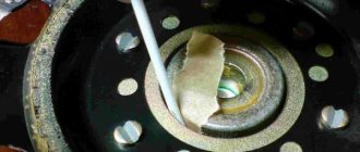
To prevent the coil from rubbing against the magnetic system, we need to set a uniform circular gap:
- Paper cut into strips is suitable for this purpose.
- We insert it in a circle (where possible) between the body and the coil, thereby obtaining a uniform gap
- We check for any jams or snags by moving the diffuser gently down and up with your hand.
Insert pieces of paper between the reel and the body
- Then we glue the suspension of our speaker and carefully insert it into place
- Give the parts time to dry
- Then you can pull out the centering papers
- Once again you need to check for jamming
- When everything is in order, add a layer of glue
- Let's dry it and put the finished subwoofer in the car for testing.
- Don't forget to turn the volume down by half.
- Subwoofer coil rewind completed
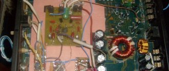
Now a little about the electronic filling
The device is almost the same, except that the dimensions are larger, the microcircuits or capacitors may be in a different order:
- Let's take a closer look at the voltage converter, power supply and amplifier
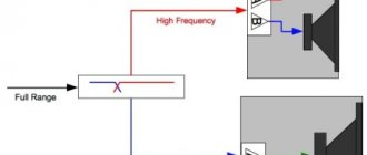
- The ceratec subwoofer amplifier is usually two-channel, but two channels are connected to one single dynamic head
- Moreover, each channel in the amplifier amplifies a different sound frequency, low and medium, as a rule
- In addition, almost all modern amplifiers operate on a single chip from the TDA series
- To get more power at the output of the amplifier, twelve volts from the on-board network of the car is not enough; for powerful microcircuits, the supply voltage is from 40 volts
- Therefore, the bw subwoofer circuit has a built-in high-frequency converter that converts the 12 volt voltage into the voltage necessary for normal operation of the amplifier
DIY subwoofer speaker rewind
I got a Kics speaker for free, but the problem was that the coil was scorched, even though it was playing. Without hesitation, I decided what I needed to do and install for myself. The first thing I did was stick the speaker out just for fun. The autopsy was performed using acetone and a knife.
I soaked the diffuser and the washer, then slowly peeled it off. The reel was all black and smelled very unpleasant.
After opening it I thought I would rewind it myself, but I became lazy. They found a “master” who rewound it for me, but I wasn’t happy for long. After 3 days the coil fell off.
The reason is that the so-called “master” did not allow the glue to dry properly and did not warm up the coil (after impregnation with BF-2 glue, it is necessary to warm up the coil for 2-3 hours at a temperature of 120-140 degrees). It was a shame, because I laid the wires, bought an amplifier, but it was of no use.
The second time I didn’t dare bring it to him, because he rewound it 3 times for a friend and the reel kept falling off.
The work of a master In the end, I realized that I needed to wind it myself. The thickness of the standard wire is 0.40, I found only 0.35, from some kind of transformer. I wound it completely by hand, impregnated it with EDP epoxy glue (I know that this is not quite the right solution, but I couldn’t find BF-2 in our city).
It turned out to lay 4 layers that were not too even, the resistance instead of 4 Ohms became 5.6 Ohms. I centered the speaker in the following sequence: I glued the diffuser, then connected the amplifier, and through the program reproduced frequencies from 10 Hz to 40 Hz while I glued the centering washer.
I made sure that nothing rubbed anywhere and left it to dry for a day.
Hand wound spool
Of course, if you pour more power into it, it will fall apart again, so the gain on the amplifier was set to 50%. It feels like it plays the same way it was played. Amplifier GZ 2-channel (bridge maximum power 600 watts into 4 ohms).
The wires were crimped into lugs, and I also added an additional wire from the generator so that the drawdowns were smaller.
Connected to the car
Power wires
How to repair a tweeter (tweeter)?
- Coil output.
- Insulating gasket.
- Suspension (elastic extension of the dome).
- Diffuser of dome design (membrane, diaphragm).
Repairing tweeters differs from repairing high-frequency and low-frequency speakers, if only because tweeters do not have a centering washer. Therefore, disassembling tweeters, even with a paper diffuser, takes much less time than disassembling midrange and bass speakers.
Often, instead of a cardboard diffuser, high-frequency speakers use a membrane made of synthetic materials. The membrane has a dome shape and, together with the suspension, forms a monolithic structure.
This design ensures minimal weight and maximum rigidity of the moving system, which is necessary for reproducing high frequencies.
Due to the very small stroke of the moving system, the process of centering the RF heads is greatly simplified. And in most tweeters with a dome-type membrane, alignment is completely ensured by the design of the dynamic head itself.
In most tweeters, the role of flexible leads is played by the coil leads, so maximum attention should be paid to their installation. One of the most common defects is the breakage of these leads. This is especially true for high-power tweeters, which, as a rule, have a greater stroke of the moving system.
Another common defect is damage to the coil, which sometimes even leads to destruction of the sleeve. The reason for this, most often, is speaker overload.
The fact is that HF heads have relatively low power. For example, in a 100-watt three-way speaker, the tweeter may be rated for only 6-10 watts of sine wave power. If such a speaker is connected to a 100-W amplifier, and the user, using a tone block or equalizer, sends even half of the amplifier’s total power to the HF head, then the HF speaker will only have to squeak for the last time.
To write this section, a friend provided me with a pair of faulty 4GDV-1 HF speakers. These speakers failed due to overload, and an interturn short circuit occurred in the coils.
I took several photos during the restoration of these speakers and tried to comment on each one.
I began the disassembly by removing the bell, which was secured with plastic latches.
Tweeters in which the diffuser is attached to the body with screws are the best to repair.
After removing the four M3 screws, it became possible to separate the centering plastic flange from the housing and free the moving speaker system.
But this is not always so easy to do. Sometimes the suspension is glued to the body elements and then the moving system must be separated with the utmost care.
In other cases, the suspension is lubricated with some kind of thick lubricant to prevent unnecessary vibrations from occurring if the suspension is not pressed tightly enough.
The dynamics of this design do not provide separate flexible leads and their functions are performed by the coil leads.
To increase reliability, the coil terminals are secured with narrow paper tape.
The flange has recesses into which the coil leads are placed.
In this picture you can see that the coil leads go through the slots.
Rewinding the HF speaker coil is done in the same way as speakers of other frequency ranges.
True, in the collection of my templates there was no mandrel of the required size, so I made a template from an electrolytic capacitor of a suitable diameter. How to do this is described in detail here.
But, if you do not have very good eyesight, you will have to use additional optics. The diameter of the wire used to wind the tweeter coils is usually less than 0.1mm.
In particular, the 4GDV-1 speaker coil is wound with wire with a diameter of only 0.08 mm. In such cases, I use binocular glasses with additional attachment lenses.
The paper tape securing the coil terminals turned out to be glued with 88-grade glue. To avoid damaging the sleeve, when removing the old coil, I soaked the adhesive joint only in those places where the coil leads were to be laid.
After laying the leads, I closed the ends of the tape and glued them with BF glue.
In some tweeters, the coil leads are glued to the suspension. This prevents the occurrence of parasitic resonance, which can accelerate the destruction of the leads. In this case, you need to use the most elastic adhesives, such as “Rubber”, “Elastosil” and the like.
Assembling the speaker is done in the reverse order and is not difficult, since the alignment of the moving system is ensured by the speaker design itself.
Before final assembly, you can check the phasing of the speaker, since, with such a small stroke of the moving system, it is more difficult to do this after assembly.
With correct phasing, the moving system should “jump” out of the housing.
You can remove varnish from the coil terminals using an Aspirin tablet. Here I already told how this can be done, and here I showed it.
Return to top to "Navigation".
Rewinding speakers
In addition to damage to the suspension, diffuser and mechanical particles getting into the gap of the magnetic system, owners of acoustic systems sometimes have to deal with a more serious defect. This is a DIY speaker rewind. More precisely, its voice coil. In rare cases, it is necessary to rewind a working coil, if this is required by matching the speakers with the low-frequency amplifier. Rewinding requires complete disassembly, except for the magnetic system. The main electrodynamic heads used in household appliances do not have a dismountable design. Only high-power heads used for sounding large areas allow repeated dismantling and subsequent reassembly.
Speaker repair
If extraneous noise appears in the speakers, there is no need to throw them away immediately. Curing poor sound quality is not that difficult. Noise in equipment is quite common, and the cause can be either a breakdown or simple contamination of the equipment. The Zvukoremont.rf workshop provides equipment repair services, including repair of acoustic systems. Thanks to the excellent professional qualities of our employees and good parts in stock, you can receive repaired speakers in the shortest possible time. Our company repairs and rewinds speakers from well-known manufacturers and provides a guarantee for all services.
How to rewind a speaker with your own hands
If the loudspeaker of the acoustic system fails, you should not immediately remove it and start disassembling it. Often the cause of failure is a simple break in the connecting wires in the speaker or the conductors running from the audio winding to the speaker contacts. Only after checking all circuits using a tester can you begin dismantling. To remove the speaker coil, you need to perform a series of operations sequentially. All work should be carried out on a comfortable table. First you need to remove the speaker from the speaker system by unsoldering the connecting wires and unscrewing the mounting screws. Then unsolder the conductors coming from the audio winding to the terminal block. This must be done very carefully, since the connecting conductors have a rope structure, where thin copper strands are intertwined with thin cotton threads.
How speaker coils are wound
Replacing or rewinding a speaker coil with your own hands begins with peeling off all the elements of the moving system. First you need to dismantle the dust cap or membrane, which is dome-shaped and located in the central part of the diffuser. In order to separate it without damage, apply a solvent to the gluing area around the perimeter of the cap. You can use a plastic syringe with a needle with a sharpened tip. The solvent is poured into the syringe and applied in a thin strip to the gluing area. The solvent must be applied very carefully so that it does not spread over the surface of the diffuser. It is not recommended to use a brush for this purpose, as hair may come off and get caught in the gap of the magnetic system.
Adhesive compositions may differ on different models, so it is best to start with alcohol and then move on to more active substances, such as solvent 646 or acetone. To prevent rapid evaporation of the solvent, after application, the dynamic head must be placed in a plastic bag. After 10 minutes, the membrane is easily separated using a thin plate.
Repairing the speaker - a guide in pictures
Today, the number of lovers of good sound who simply throw away a wheezing speaker is not decreasing! At the same time, the cost of an analogue can amount to a significant amount. I think that the following will help anyone who has hands that grow from the right place to fix the speaker.
Go!
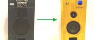
Available - a miracle of design thought, which was once a speaker S-30 (10AC-222), now serving as one of the autosubs. A week after the mutation, the patient began to show signs of the disease - he made extraneous sounds when practicing bass lines, and wheezed slightly. A decision was made to perform an autopsy.
After the autopsy, the diseased organ was removed from the patient’s body - a LF speaker 25GDN-1-4 produced in 1986. The organ clearly needed surgery - when you gently pressed the diffuser, an extraneous sound was heard (very similar to a quiet click), and when ringing with different tones (produced by the nchtoner program), a clearly audible scratching-crackling sound was heard with a large stroke of the diffuser and when applying ultra-low (5-15 Hz) ) frequencies. It was decided to trepanate this organ
First, the patient's flexible lead wires were unsoldered (from the side of the contact pads)
Then, with a solvent (646 or any other capable of dissolving glue, such as “Moment”), using a syringe with a needle, the place where the dust cap and diffuser were glued together (around the perimeter) was moistened...
…the place where the centering washer is glued to the diffuser (along the perimeter)…
...and the place where the diffuser itself is glued to the diffuser holder basket (again along the perimeter)
The speaker was left in this state for about 15 minutes with periodic repetition of the previous three steps (as the solvent was absorbed/evaporated)
Attention! When working with solvent, you should observe safety precautions - avoid contact with skin (work with rubber gloves!) and mucous membranes! Don't eat or smoke! Work in a well-ventilated area!
When wetting, use a small amount of solvent, avoiding getting it on the place where the coil and centering washer are glued!
Depending on the type of solvent and air temperature, after 10-15 minutes of the above operations, using a sharp object, you can carefully pry up the dust cap and remove it. The cap should either come off very easily or offer very little resistance. If you need to apply significant force, repeat the operations by wetting its edges with solvent and waiting!
After peeling off the cap, carefully pour out the remaining solvent from the recess near the coil mandrel (by turning the patient over).
By this time the centering washer has time to come off. Carefully, without any effort, separate it from the diffuser holder basket. if necessary, re-wet the gluing area with solvent.
We wet the place where the diffuser is glued to the diffuser holder. We wait... We wet it again and wait again... After 10 minutes you can try to peel off the diffuser. Ideally, it should effortlessly separate from the diffuser holder (along with the coil and centering washer). But sometimes he needs a little help (the main thing is to be careful! Do not damage the rubber suspension!!!)
We clean the gluing areas from old glue and dry the disassembled speaker. We examine the disassembled patient to determine if there is a malfunction. Let's look at the reel. If there are no abrasions or loose threads on it, we leave it alone. When a thread comes off, glue it back with a thin layer of BF-2 glue.
We carefully inspect the place where the supply wires are attached to the diffuser. So it is - the patient has the most common malfunction found in old speakers with a large cone stroke. The supply wire at the attachment point is frayed/broken. What kind of contact can we talk about when everything hangs on a thread running through the center!
Carefully bend the copper “tendrils”...
...and unsolder the supply wire.
We repeat the operation for the second transaction (even if he is still alive - the disease is easier to prevent!)
We cut off the supply wires at the break point...
... and tin the resulting ends (of course, we use rosin first). Care is required here! Use a small amount of low-melting solder - the solder is absorbed into the wiring like a sponge!
Carefully solder the wiring into place, bend the copper “antennae” and glue it with glue (Moment, BF-2) where the wiring connects to the diffuser. Let us remember - you cannot solder wires to the mounting “antennae”! Otherwise, how can the wiring be changed again in ten years?
Assembling the speaker. We place the diffuser with all the “equipment” in the diffuser holder, orienting the wiring to the places where they are attached. Then we check the correct polarity - when connecting a 1.5V AA battery to the terminals, when connecting the “+” battery to the “+” speaker, the diffuser will “jump” out of the basket. We place the diffuser so that its “+” supply wire is at the “+” mark on the speaker basket.
We solder the lead wires to the contact pads. Please note that the length of the wires has decreased by almost half a centimeter. Therefore, we solder them not as it was at the factory - to the hole in the plate, but with a minimum margin, to maintain the length.
We center the diffuser in its basket using photographic film (or thick paper), which we place in the gap between the core and the coil. The main rule is to place the centering evenly around the perimeter to maintain the same gap. The amount (or thickness) of centering should be such that when the diffuser is slightly protruded outward, it will freely rest on it and not fall inward. For the 25GDN-1-4 speaker, 4 pieces of photographic film, placed in pairs in front of each other, are enough for this. The length of the photographic film should be such that it does not interfere if you place the speaker on the diffuser. Why - read below. Glue the diffuser. We use the indication for the glue used (I recommend “Moment”, the main selection criterion, so that the glue can later be dissolved with a solvent). I usually stick the diffuser 1-1.5 cm up so that the centering washer does not touch the diffuser holder basket, then I apply a thin layer of glue to it and the basket with a brush, wait and firmly push the diffuser inside, additionally pressing the washer to the basket around the perimeter using my fingers . Then I glue the diffuser (in the retracted state, avoiding distortion).
We leave the speaker upside down for several hours under a load (this is why our photographic film should not protrude beyond the plane of the diffuser!)...
Then we check the speaker for correct assembly. We take out the centering and carefully check the movement of the diffuser with our fingers. It should walk easily, without making overtones (there should be no touching of the coil and the core!). We connect the speaker to the amplifier and feed it low-frequency tones at a low volume. There should be no extraneous sounds. If the gluing is incorrect (misalignment, etc.), the speaker must be unstuck (see above) and reassembled, being careful! With high-quality assembly, 99% of the time we will get a fully working speaker.
We coat the edge of the dust cap with glue, wait and carefully glue it to the diffuser. Care and precision are required here - a crookedly glued cap does not affect the sound quality, but it greatly spoils the appearance of the speaker. When gluing, do not press on the center of the cap!!! This may cause it to bend and you will have to peel it off, straighten it, coat the inside with a thin layer of epoxy for strength and glue it back.
We wait until all the parts are completely glued together (about a day) and put the finished speaker in its place. We enjoy the sound, which is no worse than that of a new factory similar speaker.
That's it, now you see that fixing the speaker is an easy task. The main thing is slowness and accuracy! So, in an hour, you can leisurely repair almost any woofer or midrange speaker, domestic or imported (for gluing up imported speakers, a more powerful solvent is often required, such as acetone or toluene, be careful - they are poisonous!!!) that has a similar defect.
Yes, after the operation, the former patient got his second wind and the cheerful yellow subs continue to do their hard bass work:
Winding the speaker coil
Next, you need to peel off the diffuser in the same way. The perimeter of the acoustic reflector is quite large, so it should be separated gradually. First, a small area is generously saturated with solvent. After some time, when the solvent is absorbed, you need to use a thin and sharp plate to separate the edge of the diffuser from the metal basket. To prevent it from sticking back, a thin plastic plate is placed under it. Gradually the entire perimeter is processed in this way. The next stage of disassembly is the separation of the central suspension. This is not always possible to do. This structural element can be glued so reliably that even prolonged treatment of the gluing area with a solvent does not always lead to the desired result. In this case, you will have to cut off the central suspension. This must be done with a very sharp object and as close to the gluing site as possible. Then the structure can be restored without problems. After the diffuser along with the sound winding is removed, you need to seal the gap of the magnetic system with tape to prevent any mechanical particles from getting there.
Do-it-yourself speaker coil winding repair usually involves two operations. This is the restoration of “flying” turns and complete rewinding of the product. It happens that measuring the winding resistance shows that the winding is intact, but some turns have become unstuck and create an obstacle to its normal movement in the magnetic system. In this case, you need to carefully put the coils in place using tweezers or another tool. The work is painstaking, labor-intensive and time-consuming. It is best to lay and align 1-2 turns, fixing them with glue. BF-2, BF-4 or any alcohol-based adhesive is used as glue. As a last resort, the wire for the speaker coils can be fixed with nitrocellulose-based glue. If during operation the thin wire breaks, you will have to rewind the speaker coil, completely removing the old winding.
Repair of subwoofer SVEN HA680W. Part II. Rewinding the Speaker Coil
Page 1 of 2
Repairing a dynamic head (speaker) is a labor-intensive process, especially if it involves the need to rewind the coil of the electromagnetic system, since this operation requires almost complete disassembly of the speaker and removal of its cone. It is advisable to carry out such complex repairs if the price for a new dynamic head is sufficiently high, the necessary tools and materials are available, as well as initial knowledge in the field of electronics.
The article discusses a relatively simple case of restoring a speaker coil: without the need to make a new base for the coil (the aluminum base is well preserved); Due to the considerable power of the speaker, an enamel wire of an impressive cross-section is used, which is easy to install.
To rewind the speaker coil we will need the following basic tools and tools:
- A cylindrical, all-metal mandrel (blank) for installation inside the reel frame during the winding process.
- Glue "BF-2". Glue "Moment". Acetone. Ethanol.
- Enameled wire (enamel wire) of a certain length and cross-section, for the manufacture of a new coil winding.
- Winding machine.
- Calipers.
- Electric soldering iron.
100 ml bottle with BF-2 glue. No more than 10 ml is consumed per coil rewind.
Aluminum (continuous) mandrel. The outer diameter is 49.5 +/-0.05 mm. The diameter of the internal hole is 8 mm. Length - about 60 mm.
Coil IEK KU 09-18 (24V) as a source of winding wire. Before winding, the wire must be thoroughly straightened and rewound onto another storage reel, which has a round shape.
Disassembling the speaker
Most dynamic heads are not intended for disassembly and are, as it were, disposable (non-separable, difficult to repair) components of speaker systems. In practice, it is often possible to successfully disassemble a speaker of a standard design and reassemble it again. The main task is to soften the glue that holds together the many components of the speaker, and separate them from each other without injury or deformation.
Speaker device.
The speaker mounting screws have a hex slot (photo on the left). Subwoofer without speaker (photo on the right).
Subwoofer speaker (before repair).
The speaker is marked "10P32", probably indicating a diameter of 10 inches and an impedance of 3.2 ohms.
The sequence of operations is as follows.
First, we unsolder the flexible braided conductors (current leads) from the socket on the speaker basket.
Secondly, remove the dust cap. To do this, saturate the adhesive seam with acetone (for example, a syringe with a needle), and use the tip of a knife to separate the cap from the diffuser. Based on the results of this operation, a conclusion should be drawn about the quality of softening the glue with acetone, and the need to use some other solvent.
Removing the dust cap.
Thirdly, we disconnect the upper suspension of the diffuser from the basket, soaking the adhesive seam with solvent. In the case of repairing a subwoofer speaker that has a durable rubber surround, the task is greatly simplified.
Disconnecting the upper diffuser suspension from the speaker basket.
Fourth, very carefully separate the centering washer of the lower diffuser suspension from the speaker basket. To do this, generously saturate the adhesive seam with solvent, wait a few minutes, and slowly, using a small flat-head screwdriver, separate the washer from the basket.
Disconnecting the centering washer (lower diffuser suspension) from the speaker basket.
The diffuser should now be free to remove from the basket. There is no need to peel off the centering washer from the diffuser.
Speaker without diffuser.
The diffuser is marked “YC-246A”.
We evaluate the condition of the electromagnetic system of the speaker: coil, permanent magnet. In our case, the original coil of the SVEN speaker, wound with a copper enamel wire of round cross-section, had a deplorable appearance: the enamel was blackened from excessive heating, several outer turns had peeled off, the coil unwinds easily (the glue has completely burned out). Most likely, this was a consequence of the failure of the subwoofer power amplifier. The conclusion is obvious - a complete replacement of the coil wire is necessary.
Condition of the old voice coil. The aluminum frame was not damaged.
Selecting wire for winding
A simple way to determine with sufficient accuracy the required length of a new wire is to calculate the length of one turn (knowing its radius), multiply by the number of turns in a layer and by the number of layers. The SVEN subwoofer speaker has a four-layer coil with 34 turns in each layer.
According to measurements, the outer diameter of the burnt coil is 53 mm, therefore, the length of one turn (at maximum, on the surface of the coil) is: 53 x 3.14 = 166.42 mm. We multiply this length by the total number of turns in the coil: 166.42 x 34 x 4 = 22633.12 mm.
Thus, rounding up (adding a small margin), to rewind the coil we need at least 23 meters of enameled wire.
The outer and inner diameters of the burnt coil are 53 and 50 mm, respectively (measurements are approximate due to the presence of winding deformations).
The diameter of the wire is determined using a micrometer or caliper. The circular cross-sectional area is calculated using the well-known formula: S = Pi x R2, where R is the radius of the wire. It is necessary to measure the diameter of the wire both by copper (with the varnish insulation removed) and by insulation (the outer diameter of the future coil is also important for us). To remove insulating varnish from a wire, when measuring the diameter on copper, it is necessary to heat the tip of the wire until red (burn the varnish) and remove combustion products with a solvent.
According to the measurement results, the burnt coil of the subwoofer speaker was wound with a wire with a diameter of 0.38 mm on copper (section 0.113 sq. mm) and 0.44 mm on varnish. Now we have a very difficult task - to find the same, or very close, wire. If you can’t buy the wire you need, you can wind it from some electronic device. For example, coils of electromagnetic contactors (starters) have proven themselves to be good donors for enamel wires.
Depending on the voltage and type of contactor, their coils use wire of different sections and lengths.
Diameter of the burnt coil wire. For copper - 0.38 mm (photo on the left); for varnish - 0.44 mm (photo on the right).
Wire diameter for new winding. For copper - 0.35 mm (photo on the left); for varnish - 0.40 mm (photo on the right).
If, as a result of a long search, it was not possible to find the original wire, then you can use a wire of a different cross-section, recalculating the number of turns, layers and coil resistance.
It must be remembered that by changing the cross-section of the wire, the characteristics of the dynamic head change, as well as the magnetic gap and winding height.
Before deciding to use a “foreign” wire in coil winding, you need to accurately calculate the geometric and electrical parameters of the future coil, and predict the operation of the dynamic head with new parameters in the speaker system.
To rewind the speaker coil from the SVEN subwoofer, we managed to find a wire with similar parameters (0.35 mm in diameter for copper, 0.40 for varnish) in the KU 09-18 (24V) coil of the IEK contactor. The length of the wire in the contactor coil was almost twice the required value.
Winding data (copper wire diameter and number of turns) in the coils of starters of the PME and PAE series for a current frequency of 50 Hz
PME-000.
| Voltage, V | 36 | 127 | 220 | 380 |
| Wire diameter, mm | 0,31 | 0,16 | 0,12 | 0,09 |
| Number of turns | 800 | 3000 | 5300 | 9000 |
PME-100.
| Voltage, V | 36 | 127 | 220 | 380 | 500 |
| Wire diameter, mm | 0,38 | 0,2 | 0,15 | 0,11 | 0,1 |
| Number of turns | 660 | 2400 | 4150 | 7170 | 9430 |
PME-200.
| Voltage, V | 36 | 36 | 110 | 110 | 127 | 127 | 220 | 220 | 380 | 380 | 500 |
| Wire diameter, mm | 0,57 | 0,67 | 0,33 | 0,38 | 0,31 | 0,35 | 0,23 | 0,27 | 0,18 | 0,20 | 0,18 |
| Number of turns | 442 | 426 | 1350 | 1300 | 1560 | 1500 | 2700 | 2600 | 4660 | 4500 | 5900 |
| Wire brand | PETV | PEV-2 | PETV | PEV-2 | PETV | PEV-2 | PETV | PEV-2 | PETV | PEV-2 | PEV-2 |
PAE values III and IV.
| Voltage, V | 36 | 36 | 110 | 110 | 127 | 127 | 220 | 220 | 380 | 380 | 500 | 500 |
| Wire diameter, mm | 0,62 | 0,90 | 0,38 | 0,47 | 0,35 | 0,47 | 0,27 | 0,35 | 0,2 | 0,27 | 0,17 | 0,23 |
| Number of turns | 350 | 260 | 1070 | 800 | 1230 | 920 | 2130 | 1600 | 3680 | 2760 | 4850 | 3640 |
| Starter size | III | IV | III | IV | III | IV | III | IV | III | IV | III | IV |
PAE values V and VI.
| Voltage, V | 36 | 36 | 110 | 110 | 127 | 127 | 220 | 220 | 380 | 380 | 500 | 500 |
| Wire diameter, mm | 1,2 | 1,56 | 0,69 | 0,83 | 0,64 | 0,83 | 0,49 | 0,62 | 0,35 | 0,47 | 0,31 | 0,41 |
| Number of turns | 198 | 147 | 605 | 445 | 700 | 516 | 1200 | 890 | 2070 | 1540 | 2730 | 2020 |
| Starter size | V | VI | V | VI | V | VI | V | VI | V | VI | V | VI |
How to make a speaker winding
Winding speaker coils is a delicate and responsible job. Whether the loudspeaker will work or will have to be thrown away depends on the quality of its implementation. First, the old winding should be wound, while counting the number of turns. This data will be useful for winding a new product. If the wire has not burned out or crumbled, you can not count the turns, but measure the length of the wire. Then its diameter is determined with a micrometer and, based on these data, the wire for rewinding the speaker is selected. It often happens that the paper sleeve is badly damaged. In this case, you will have to not only change the winding, but also make a new frame yourself. In order for the production of the sleeve and winding to be successful, you will definitely need a mandrel on which these works will be carried out. Using a mandrel will make the work more convenient and prevent the paper core from deforming during the winding process. If rewinding speakers with your own hands is a one-time operation, then a mandrel of the required diameter is made from any material that can be easily processed. Those who regularly repair loudspeakers will need a set of metal split mandrels.
The cut is needed so that the mandrel can be slightly compressed and the finished product can be removed from it.
Rewinding the speaker voice coil
When loudspeaker systems are operating efficiently at maximum volume levels, it is rare for a sound system to burn out neatly and in one place. Usually, after disassembling the loudspeaker, black and charred coils are visible. If the frame is made of paper, then it also burns badly and needs to be replaced. Special paper is used as material for the sleeve. There cannot be specific recommendations here, since the material that is at hand is used. Thin aluminum foil with a diameter of 0.05-0.1 mm is well suited for making a voice coil sleeve. The base will be light, and thin metal will remove heat better.
The most important thing when winding is the use of appropriate glue. Very often, after restoring the voice coil, the loudspeaker, after some time, failed again. The winding did not burn out, but its turns slipped off the sleeve due to the fact that low heat-resistant glue was used during operation. Many modern adhesives soften at temperatures of 80-1000C, so the result of the work depends on the choice of glue. Alcohol-based glues such as BF-2, BF-4, BF-6 give excellent results, but they are difficult to obtain. For low-frequency and high-power loudspeakers, aluminum foil from soft drink cans is a good material for the sleeve.
Valentinych.ru
If the speaker worked, but “creaked”, which sometimes happens when the coil “collapsed”, then you can try to glue the loose turns of the coil. To do this, they need to be carefully placed in their old place, and simply coated with two or three layers of glue, with intermediate drying. It happens that one of the coil terminals is simply unsoldered from the current conductor or intermediate flat busbar as a result of overheating. In this case, it is enough to simply solder it in place. Of course, you should not use low-temperature tubular solders for this; it is much better to use classic POS. If the coil not only fell apart, but also turned black from overheating, and the varnish insulation of the wire became charred, then it is definitely better to rewind the coil. For speakers with known coil parameters (wire diameter, number of layers, and number of turns in each layer), you can simply remove the remnants of the old coil winding. If the number of turns is not known, then you should carefully wind each layer of the winding, counting the turns. Then you should select a piece of coiled wire with intact insulation, and, measuring the diameter of the wire with a micrometer, select a wire with the closest possible diameter. If this was not possible, then knowing the number of turns and the DC resistance of the coil, you can calculate the required wire diameter. Here is the formula for such calculations:
d = √(ρ(πn(D+bm)+k)/(250πR)),
where: d – voice coil wire diameter (mm), ρ – copper resistivity (0.0175 Ohm*mm²/m), n – total number of coil turns, D – outer diameter of the coil frame (mm), b – approximate wire diameter (mm), m – number of winding layers, k – total length of the coil leads from the outer turns of the winding to the place of soldering to flexible current leads, R – coil resistance to direct current (Ohm), n – pi number. The value b is approximate and is necessary for a more accurate calculation of the average length of the voice coil turn. You can specify b with an accuracy of +/-0.1 mm from the actual diameter, without significantly reducing the accuracy of the calculations. The given formula looks like this:
d = √((πn(D+bm)+k)/44880R).
The same formula can be used when recalculating the voice coil resistance to a different value. To rewind the speaker coil, it is worth making a special winder with replaceable split mandrels. Its design is simple and clear from the photographs given: 1, 2, 3.
This winder is already more than 20 years old, and dozens of coils have been rewound on it. These are just two plates of textolite (which were on hand), connected by four M5 screws. A hole with a diameter slightly smaller than the diameter of the winder axis is drilled along the plane of connection of the plates. The design allows you to regulate the amount of friction between the shaft of the winder and its body, which is quite convenient when working with wires of different diameters. This braking of the axis prevents spontaneous rotation of the axis and prevents the loosening of the coils during inevitable pauses in operation. You can also use dense wood as plates (beech, oak, hornbeam, birch), but it seems to me that PCB is more durable. Split mandrels are sharpened to each diameter of the voice coil (I already have a couple of dozen of them) with a plus tolerance of approximately 0.05-0.07 mm. A split mandrel is needed so that the tightly wound coil, after completion of work, would be easier to remove from the mandrel by slightly squeezing it.
The plastic coil frame of the speaker shown in the photo was not damaged (which most often happens with paper frames), and I did not peel it off from the diffuser. If the paper frame is damaged, you have to make a new one. After several experiments on choosing material for the frame, I settled (back in those ancient times) on paper punched cards from ancient computers like “Minsk-32”, etc. I think that now it will be problematic to find such punched cards, but if you want, it’s possible. A good alternative to paper for making coil frames is aluminum foil with a thickness of 0.05-0.1 mm. I still have stocks of 0.06 mm thick foil, which used to be used to make lids for glass kefir and milk bottles. This foil is quite soft, easily smoothed out after an accidental jam, and most importantly, it does not spring and does not strain the copper winding of the coil. The weight of a frame made of such foil is practically no more than the weight of a paper frame. Great stuff! For large-diameter coils (powerful low-frequency speakers), foil from beer cans is quite suitable. True, it is quite rigid, so before winding, a strip of such foil of the required length should be wound on a round mandrel with a diameter 2.5-3 times smaller than the diameter of the diffuser coil, and tightly wrapped over the entire width, for example, with electrical tape. After being “released” in a few hours, the strip of foil will have just the diameter you need. The advantage of the metal frame is its increased thermal conductivity, which significantly facilitates the thermal regime of the voice coil. A little trick to make the winding process easier: be sure to install limiting borders 2-3 mm high on both sides of the future winding, this will allow you to wind the coil “from wall to wall”, without fear of the lower layer of turns spreading when winding the upper layer(s). ev). Curbs are best made from split plastic washers of the required diameter. In extreme cases (as in my photo near the right cheek of the mandrel), you can simply wind one turn of electrical wire in plastic insulation in the right place. In this case, I wrapped the left border with some kind of self-adhesive elastic plastic (car decorative molding). Before winding, the surface of the metal frame must be degreased. I use isopropyl alcohol (at any radio store - 30 rubles for 0.25 liters). After this, the surface of the frame between the borders is coated with a thin layer of glue. Previously I used exclusively BF-2. Nowadays it’s difficult to get such glue from us, so I buy BF-6 in pharmacies, a close relative of BF-2 with slightly worse adhesive and strength properties. I do not recommend using newfangled instant adhesives such as “88”, “Moment” or “Super-moments” (cyanoacrylate based) due to a number of their properties, which do not facilitate gluing and impregnation of voice coils. Only alcohol glue, or, as a last resort, some kind of nitrocellulose-based glue (you can pick up something from furniture varnishes).
The photograph shows a foam roller rotating on a thin steel axis, which is generously saturated with glue immediately before winding begins. I make the roller from a piece of foam rubber placed on a piece of a pen refill. Before laying it on the frame, the wire touches the glue-impregnated foam rubber, and falls on it (the frame) already smeared with glue. This simple device significantly improves the sizing of the reel. When winding, the wire is also degreased - this is not visible in the photo (it was photographed before work began, and the roller was not yet soaked in glue), but usually I hold the wire with a napkin soaked in the same isopropyl alcohol.
The next photo shows a “fresh” three-layer coil, which took me no more than 5-7 minutes to wind. After the coil has been wound and slightly dried with hot air (the easiest way is to use a household hair dryer), it makes sense to additionally soak it in 2-3 layers with the same glue, perhaps slightly diluted with ordinary alcohol. I do this using a foam swab.
Until it dries completely (about 24 hours), the coil is left on a split mandrel. Then the restrictive borders are removed from the coil, the coil itself is removed from the split mandrel, and the leads of the coil winding are unsoldered. After this, the outer turns of the coil and the soldering points are soaked with glue another 2-3 times, always with intermediate drying for 1-2 hours, and the coil is finally dried. You can also use a heat gun to speed up the drying of each layer of glue.
Pages: 2
Replacing the speaker coil
Before you start winding, you need to calculate the speaker coil. Typical speaker impedance is 4 or 8 ohms. If you know the size of the sleeve, the length of the wire and its diameter, then it is enough to measure the required piece of copper wire and wind it. It must be wound turn to turn in two or three layers. First, the gasket is screwed onto the mandrel, then the sleeve. The coils must be fixed with glue during the winding process. How to wind a speaker coil.
Winding is carried out strictly turn to turn, so in order for the winding to fit neatly on the sides of the sleeve, you need to make sides from thick paper. In this case, you will only have to monitor the evenness of the winding. The wire for rewinding the speakers can be PEV-1, PEV-2 or PEVTL. The latter type is preferable as it has a higher resistance to heat. When repairing a loudspeaker with your own hands, it is not recommended to change the diameter of the wire.
DIY speaker coil repair
To obtain an even winding on the mandrel, it is best to use a winding machine. You can do it yourself or use a ready-made tool. A hand drill secured in a vice will do. After the coil is ready, it should be glued with heat-resistant glue and dried using a household hair dryer. After thorough drying, you can begin assembling the loudspeaker. It is not recommended to simultaneously glue the centering washer and the diffuser suspension to the basket. First, it is better to glue the central elastic washer. Before this, the sound system must be centered on the core of the magnetic system so that no rustling or creaking is heard during the operation of the loudspeaker. To do this, a tube is rolled up from a sheet of paper and inserted into the gap of the magnetic system between the coil and the core. Then the centering washer is glued. If, when pressed by hand, the diffuser moves smoothly and without catching, then you can glue the diffuser suspension.
Rewinding the subwoofer coil - what you need
Repairing a dynamic head (speaker) is a labor-intensive process, especially if it involves the need to rewind the coil of the electromagnetic system, since this operation requires almost complete disassembly of the speaker and removal of its cone.
It is advisable to carry out such complex repairs if the price for a new dynamic head is sufficiently high, the necessary tools and materials are available, as well as initial knowledge in the field of electronics. The article discusses a relatively simple case of restoring a speaker coil: without the need to make a new base for the coil (the aluminum base is well preserved); Due to the considerable power of the speaker, an enamel wire of an impressive cross-section is used, which is easy to install.
To rewind the speaker coil we will need the following basic tools and tools:
- A cylindrical, all-metal mandrel (blank) for installation inside the reel frame during the winding process.
- Glue "BF-2". Glue "Moment". Acetone. Ethanol.
- Enameled wire (enamel wire) of a certain length and cross-section, for the manufacture of a new coil winding.
- Winding machine.
- Calipers.
- Electric soldering iron.
100 ml bottle with BF-2 glue. No more than 10 ml is consumed per coil rewind.
Aluminum (continuous) mandrel. The outer diameter is 49.5 +/-0.05 mm. The diameter of the internal hole is 8 mm. Length - about 60 mm. Coil IEK KU 09-18 (24V) as a source of winding wire. Before winding, the wire must be thoroughly straightened and rewound onto another storage reel, which has a round shape.
Disassembling the speaker.
Most dynamic heads are not intended for disassembly and are, as it were, disposable (non-separable, difficult to repair) components of speaker systems. In practice, it is often possible to successfully disassemble a speaker of a standard design and reassemble it again. The main task is to soften the glue that holds together the many components of the speaker, and separate them from each other without injury or deformation.
Speaker device. The speaker mounting screws have a hex slot (photo on the left). Subwoofer without speaker (photo on the right). Subwoofer speaker (before repair). The speaker is marked "10P32", probably indicating a diameter of 10 inches and an impedance of 3.2 ohms.
The sequence of operations is as follows.
First, we unsolder the flexible braided conductors (current leads) from the socket on the speaker basket.
Secondly, remove the dust cap. To do this, saturate the adhesive seam with acetone (for example, a syringe with a needle), and use the tip of a knife to separate the cap from the diffuser. Based on the results of this operation, a conclusion should be drawn about the quality of softening the glue with acetone, and the need to use some other solvent.
Removing the dust cap.
Thirdly, we disconnect the upper suspension of the diffuser from the basket, soaking the adhesive seam with solvent. In the case of repairing a subwoofer speaker that has a durable rubber surround, the task is greatly simplified.
Disconnecting the upper diffuser suspension from the speaker basket.
Fourth, very carefully separate the centering washer of the lower diffuser suspension from the speaker basket. To do this, generously saturate the adhesive seam with solvent, wait a few minutes, and slowly, using a small flat-head screwdriver, separate the washer from the basket.
Disconnecting the centering washer (lower diffuser suspension) from the speaker basket.
The diffuser should now be free to remove from the basket. There is no need to peel off the centering washer from the diffuser.
Page 1 of 2
Repairing a dynamic head (speaker) is a labor-intensive process, especially if it involves the need to rewind the coil of the electromagnetic system, since this operation requires almost complete disassembly of the speaker and removal of its cone. It is advisable to carry out such complex repairs if the price for a new dynamic head is sufficiently high, the necessary tools and materials are available, as well as initial knowledge in the field of electronics.
The article discusses a relatively simple case of restoring a speaker coil: without the need to make a new base for the coil (the aluminum base is well preserved); Due to the considerable power of the speaker, an enamel wire of an impressive cross-section is used, which is easy to install.
To rewind the speaker coil we will need the following basic tools and tools:
- A cylindrical, all-metal mandrel (blank) for installation inside the reel frame during the winding process.
- Glue "BF-2". Glue "Moment". Acetone. Ethanol.
- Enameled wire (enamel wire) of a certain length and cross-section, for the manufacture of a new coil winding.
- Winding machine.
- Calipers.
- Electric soldering iron.
100 ml bottle with BF-2 glue. No more than 10 ml is consumed per coil rewind.
Aluminum (continuous) mandrel. The outer diameter is 49.5 +/-0.05 mm. The diameter of the internal hole is 8 mm. Length - about 60 mm.
Coil IEK KU 09-18 (24V) as a source of winding wire. Before winding, the wire must be thoroughly straightened and rewound onto another storage reel, which has a round shape.
Disassembling the speaker.
Most dynamic heads are not intended for disassembly and are, as it were, disposable (non-separable, difficult to repair) components of speaker systems. In practice, it is often possible to successfully disassemble a speaker of a standard design and reassemble it again. The main task is to soften the glue that holds together the many components of the speaker, and separate them from each other without injury or deformation.
Speaker device.
The speaker mounting screws have a hex slot (photo on the left). Subwoofer without speaker (photo on the right).
Subwoofer speaker (before repair).
The speaker is marked "10P32", probably indicating a diameter of 10 inches and an impedance of 3.2 ohms.
The sequence of operations is as follows.
First, we unsolder the flexible braided conductors (current leads) from the socket on the speaker basket.
Secondly, remove the dust cap. To do this, saturate the adhesive seam with acetone (for example, a syringe with a needle), and use the tip of a knife to separate the cap from the diffuser. Based on the results of this operation, a conclusion should be drawn about the quality of softening the glue with acetone, and the need to use some other solvent.
Removing the dust cap.
Thirdly, we disconnect the upper suspension of the diffuser from the basket, soaking the adhesive seam with solvent. In the case of repairing a subwoofer speaker that has a durable rubber surround, the task is greatly simplified.
Disconnecting the upper diffuser suspension from the speaker basket.
Fourth, very carefully separate the centering washer of the lower diffuser suspension from the speaker basket. To do this, generously saturate the adhesive seam with solvent, wait a few minutes, and slowly, using a small flat-head screwdriver, separate the washer from the basket.
Disconnecting the centering washer (lower diffuser suspension) from the speaker basket.
The diffuser should now be free to remove from the basket. There is no need to peel off the centering washer from the diffuser.
Speaker without diffuser.
The diffuser is marked “YC-246A”.
We evaluate the condition of the electromagnetic system of the speaker: coil, permanent magnet. In our case, the original coil of the SVEN speaker, wound with a copper enamel wire of round cross-section, had a deplorable appearance: the enamel was blackened from excessive heating, several outer turns had peeled off, the coil unwinds easily (the glue has completely burned out). Most likely, this was a consequence of the failure of the subwoofer power amplifier. The conclusion is obvious - a complete replacement of the coil wire is necessary.
Condition of the old voice coil. The aluminum frame was not damaged.Selecting wire for winding.
A simple way to determine with sufficient accuracy the required length of a new wire is to calculate the length of one turn (knowing its radius), multiply by the number of turns in a layer and by the number of layers. The SVEN subwoofer speaker has a four-layer coil with 34 turns in each layer. According to measurements, the outer diameter of the burnt coil is 53 mm, therefore, the length of one turn (at maximum, on the surface of the coil) is: 53 x 3.14 = 166.42 mm. We multiply this length by the total number of turns in the coil: 166.42 x 34 x 4 = 22633.12 mm. Thus, rounding up (adding a small margin), to rewind the coil we need at least 23 meters of enameled wire.
The outer and inner diameters of the burnt coil are 53 and 50 mm, respectively (measurements are approximate due to the presence of winding deformations).
The diameter of the wire is determined using a micrometer or caliper. The circular cross-sectional area is calculated using the well-known formula: S = Pi x R2, where R is the radius of the wire. It is necessary to measure the diameter of the wire both by copper (with the varnish insulation removed) and by insulation (the outer diameter of the future coil is also important for us). To remove insulating varnish from a wire, when measuring the diameter on copper, it is necessary to heat the tip of the wire until red (burn the varnish) and remove combustion products with a solvent. According to the measurement results, the burnt coil of the subwoofer speaker was wound with a wire with a diameter of 0.38 mm on copper (section 0.113 sq. mm) and 0.44 mm on varnish. Now we have a very difficult task - to find the same, or very close, wire. If you can’t buy the wire you need, you can wind it from some electronic device. For example, coils of electromagnetic contactors (starters) have proven themselves to be good donors for enamel wires. Depending on the voltage and type of contactor, their coils use wire of different sections and lengths.
Diameter of the burnt coil wire. For copper - 0.38 mm (photo on the left); for varnish - 0.44 mm (photo on the right).
Wire diameter for new winding. For copper - 0.35 mm (photo on the left); for varnish - 0.40 mm (photo on the right).
If, as a result of a long search, it was not possible to find the original wire, then you can use a wire of a different cross-section, recalculating the number of turns, layers and coil resistance. It must be remembered that by changing the cross-section of the wire, the characteristics of the dynamic head change, as well as the magnetic gap and winding height. Before deciding to use a “foreign” wire in coil winding, you need to accurately calculate the geometric and electrical parameters of the future coil, and predict the operation of the dynamic head with new parameters in the speaker system.
To rewind the speaker coil from the SVEN subwoofer, we managed to find a wire with similar parameters (0.35 mm in diameter for copper, 0.40 for varnish) in the KU 09-18 (24V) coil of the IEK contactor. The length of the wire in the contactor coil was almost twice the required value.
Winding data (copper wire diameter and number of turns) in the coils of starters of the PME and PAE series for a current frequency of 50 Hz.
| PME-000. | ||||
| Voltage, V | 36 | 127 | 220 | 380 |
| Wire diameter, mm | 0,31 | 0,16 | 0,12 | 0,09 |
| Number of turns | 800 | 3000 | 5300 | 9000 |
| PME-100. | |||||
| Voltage, V | 36 | 127 | 220 | 380 | 500 |
| Wire diameter, mm | 0,38 | 0,2 | 0,15 | 0,11 | 0,1 |
| Number of turns | 660 | 2400 | 4150 | 7170 | 9430 |
| PME-200. | |||||||||||
| Voltage, V | 36 | 36 | 110 | 110 | 127 | 127 | 220 | 220 | 380 | 380 | 500 |
| Wire diameter, mm | 0,57 | 0,67 | 0,33 | 0,38 | 0,31 | 0,35 | 0,23 | 0,27 | 0,18 | 0,20 | 0,18 |
| Number of turns | 442 | 426 | 1350 | 1300 | 1560 | 1500 | 2700 | 2600 | 4660 | 4500 | 5900 |
| Wire brand | PETV | PEV-2 | PETV | PEV-2 | PETV | PEV-2 | PETV | PEV-2 | PETV | PEV-2 | PEV-2 |
| PAE values III and IV. | ||||||||||||
| Voltage, V | 36 | 36 | 110 | 110 | 127 | 127 | 220 | 220 | 380 | 380 | 500 | 500 |
| Wire diameter, mm | 0,62 | 0,90 | 0,38 | 0,47 | 0,35 | 0,47 | 0,27 | 0,35 | 0,2 | 0,27 | 0,17 | 0,23 |
| Number of turns | 350 | 260 | 1070 | 800 | 1230 | 920 | 2130 | 1600 | 3680 | 2760 | 4850 | 3640 |
| Starter size | III | IV | III | IV | III | IV | III | IV | III | IV | III | IV |
| PAE values V and VI. | ||||||||||||
| Voltage, V | 36 | 36 | 110 | 110 | 127 | 127 | 220 | 220 | 380 | 380 | 500 | 500 |
| Wire diameter, mm | 1,2 | 1,56 | 0,69 | 0,83 | 0,64 | 0,83 | 0,49 | 0,62 | 0,35 | 0,47 | 0,31 | 0,41 |
| Number of turns | 198 | 147 | 605 | 445 | 700 | 516 | 1200 | 890 | 2070 | 1540 | 2730 | 2020 |
| Starter size | V | VI | V | VI | V | VI | V | VI | V | VI | V | VI |
Manufacturing of a winding machine.
The machine is a U-shaped structure that has an axis of rotation of the mandrel (blank) of the speaker coil and an axis of rotation of the coil with a supply of winding wire. For the axes, it is necessary to provide the ability to adjust the rotation forces, that is, some kind of brake, to prevent self-unwinding of the wire. Also, the design of the machine must have places for fastening the degreasing and glue-applying rollers, through which the wire will pass before it hits the speaker coil. If repairing speakers is not a frequent task, then it is enough to whip up a structure from scraps of MDF board, shown in the figure below.
Winding machine.
Previous 1 Next
Do-it-yourself rewinding of the Pioneer TS-W304R subwoofer coil.
In this article I want to talk about how to repair a burnt-out subwoofer speaker on your own. The Pioneer TS-W304R subwoofer at one point refused to play music.
Having examined it, I came to the conclusion that there was a short circuit in the coil.
Disassembly was carried out at home in domestic conditions. Anyone can repair a coil. The main thing is to have your hands and a little patience.
1) Nail polish remover
5)Rubber glue moment
Let's get started: First we need to peel off the suspension. Take a syringe and apply nail polish remover to the back of the speaker. Then we apply varnish on the back side under the plastic frame.
Next, we tear off the washer and suspension using a screwdriver. (We do the installation very carefully!)
Disconnect the centering washer. We also saturate the glue with liquid along the edges of the washer.
Use a screwdriver to remove it.
We try to remove the upper part of the subwoofer. In my case, the coil body was lifted.
And so about the malfunction: An interturn short circuit has occurred. The sub played and got very hot (played in a clip) and the varnish lost its strong properties due to high temperatures. The device shows unstable resistance when the diffuser position changes.
It seemed to me that the cooling of this subwoofer was inadequate. I decided to make several side holes for ventilation in the basket. But this must be done carefully. Better yet, without magnets. If the chips are not removed. Over time, it will destroy your coil while the subwoofer is running. If you're not sure, don't drill.
Let's move directly to the coil itself. To wind it, we need the body itself; I found a can of some kind of chemical for hair. The size is perfect.
It was decided to make the speaker with a resistance of 2 ohms.
We make calculations using the formula R=P*l/S
—-where R is the resistance, l is the length, P is the density of the wire material (in our case, copper, 0.017), S is the cross-section of the wire.
We look for the length using the following formula l=SR/P
Section formula S=3.14*D²/4
—-Here 3.14 is “Pi”, D² is the diameter squared.
Solder the beginning of the wire. Using bf glue we smear the whole thing, I wrap it without tools on a metal can of chemicals. The following procedure is to solder the end of the wire to the speaker terminal.
After we glue the centering washer, we set the coil gap so that the coil does not click against the magnetic system. We do this while the glue is more or less liquid.
Out of joy, I decided to paint the basket in Graffiti style.
You can read more interesting articles on the website 100-sovetov.rf
Subscribe to the channel, there will be many interesting articles. Thumbs up if you liked the article.
Crossover calculation for acoustics: do it yourself
Crossover calculation for acoustics75
Calculating the crossover for acoustics, as you know, is a very important operation. There are no ideal acoustic systems in the world that can reproduce the entire frequency range. And then certain parts of the speaker spectrum come to the rescue. For example, if you need to reproduce low frequencies, use a subwoofer, and to reproduce high frequencies, install midbass.
When all these speakers together start playing, confusion can occur before reaching one or another emitter. For this reason, an active or passive crossover for acoustics is necessary.
In this article we will learn why filter calculations are needed, consider passive crossovers, and learn how they are built using inductors and capacitors.
Homemade crossovers for car acoustics
To connect a 2-way (see Two-way acoustic system and its advantages) or other acoustics with a large number of bands to 1 channel of an amplifier or PG, you need some kind of separate device that separates the signal. At the same time, it must allocate its own frequencies for each band. These devices are called filters or crossovers.
Note. As a rule, component speakers already come with a passive crossover. It was prepared by the manufacturer and was designed from the very beginning.
But what if you need to divide the frequencies according to a different scheme (for example, if a set of acoustics is assembled from separate components)? In this case, we are talking about calculating the crossover. Let us note right away that calculating the crossover is not at all difficult and you can even make it yourself.
Crossovers for acoustics for Pioneer cars professional
Below are instructions on how to calculate the crossover:
- Download a special program. This could be Crossover Elements Calculator on your computer;
A special program for calculating crossover Crossover Elements Calculator
- We enter the resistance of the low-frequency and high-frequency speakers. Impedance is the nominal value of the acoustic impedance, expressed in Ohms. Typically, the average value is 4 ohms;
- Enter the crossover frequency. Here it will be useful to know that the frequency must be entered in Hz, but in no case in kHz.
Note. If the crossover is of the second order, then you must also enter the type of crossover.
- You can get the expected result by clicking on the calculation button.
In addition, you need to know the following:
- The capacitance of capacitors, or rather their value, is entered in Farads;
- Inductance is calculated in Henry (mH).
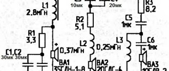
The filter calculation scheme looks something like this:
How to calculate a filter
Filters of different order
To clearly understand the crossover calculation scheme (see Homemade crossovers for acoustics and their purpose), you need to understand the difference between filters of different orders. This will be discussed below.