Germanium above all? Long live experimentation!
The proposed stereo audio power amplifier (UMPA) is made using circuit design more than half a century old with one voltage amplification stage. Its distinctive feature is the use of “sound” silicon transistors.
Among lovers of high-quality sound reproduction, a similar structure based on germanium transistors is still popular [1-4]. And the high quality of sound reproduction of these amplifiers is explained by the “wonderful properties” of germanium. By comparing two designs with a similar circuit diagram, made on different element bases, you can verify in practice whether this is so.
Looking ahead, I will say that in the end we got three decent amplifiers. Both silicon and germanium are good with the right circuit design. Happy creativity!
Contents
- 1 Germanium is playing! 1.1 Ways to improve the known scheme
- 1.2 Schematic diagram of a modified UMZCH on germanium transistors
- 1.3 Characteristics of the modified amplifier
- 1.4 Recommended power supply
- 2.1 Amplifier circuit of a similar structure, but on silicon
Transistor amplifiers
B. Khokhlov High-quality low-frequency amplifier. - Radio, 1960, No. 2, pp. 27, 28
The author describes a power amplifier using transistors P11, P13, P201 with a tone control and a stabilized power supply. The amplifier has a maximum output power of 6 W at a load of 8 Ohms, a reproducible frequency band of 30 - 20,000 Hz, frequency response unevenness - 3 dB, nonlinear distortion of no more than 5%. Subsequently, this circuit was repeated on a base of elements that was more modern for that time (usually this circuit was implemented on germanium transistors).
In the same article, the author provides a tone correction diagram:
The frequency response of this tone compensator is given below:
The power amplifier can be powered with a voltage of 12V, the output power will be 3-4 W.
Transformerless amplifier using transistors. - Radio, 1961, No. 10, pp. 57,58
Amplifier output power 2-2.5 W, reproduced frequency range 10 Hz - 20 kHz, nonlinear distortion factor 3-4%, sensitivity - 30 mV.
I. Zhuravlev, V. Belousenko On the selection of transistors for high-quality low-frequency amplifiers. - Radio, 1968, No. 2
By the beginning of 1968, the circuit of a transformerless amplifier using transistors took on the following form:
At the same time, to achieve maximum sound quality, it was noted that it was necessary to select transistors. It was noted that with a careful approach to selection, it is possible to achieve a harmonic coefficient of 0.5-0.8% with an output power of 8-15 W. The article provides a diagram and description of the methodology for selecting transistors:
↑ Germanium is playing!
Currently, germanium transistors are almost completely replaced by silicon ones, which have better parameters and, most importantly, better temperature stability.
The decisive reason for replacing germanium transistors with silicon ones was the higher cost and shortage of raw materials. Nevertheless, there are many germanium transistors left in the arsenals of radio amateurs, so it doesn’t hurt to once again evaluate the audio properties of germanium from a modern perspective.
Let's consider an amplifier based on germanium transistors, built according to the circuit shown in Fig. 1. The amplifier is implemented in hardware by J. Tsikhiselli, published in the AudioVideo magazine [3]. The editorial specialists highly appreciated the sound of the amplifier.
Fragment excluded. The full version is available to patrons and full members of the community.
Rice. 1. Popular UMZCH circuit on germanium transistors
The proposed circuit is a direct-coupled DC amplifier. The preliminary stage on transistor VT1 amplifies the voltage signal and operates in class A. The output stage is a power amplifier operating in class AB with a small quiescent current. It is made on powerful transistors VT4, VT5 of the same conductivity type. The cascade on complementary transistors VT2, VT3 plays the role of a bass reflex. The output stage with a bass reflex can be represented as a quasi-complementary structure. The upper arm (transistors VT2, VT4) is a composite emitter follower - a Darlington circuit, and the lower arm (transistors VT3, VT5) is an amplifier with tracking feedback, otherwise called a Sziklai circuit.
Transistors VT2, VT4 amplify the negative half-wave of the signal voltage, and VT3, VT5 – the positive half-wave.
The disadvantage of the quasi-complementary structure of the output stage is the difference in the transmission coefficients for the upper and lower arms. The transmission coefficient of the lower arm is slightly higher than that of the upper arm, although their values are very close to unity.
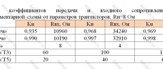
The input impedances of the arms also differ, by approximately 4–8%; the upper arm has a higher input impedance than the lower arm (see Table 1).
The noted factors naturally determine the initial level of distortion of the amplifier, before being covered by negative feedback.
To obtain the maximum possible range of the output signal, positive feedback (POS) is applied, introduced by capacitor C2 from the output of the amplifier to the connection point of load resistors R4 and R5, increasing the equivalent load resistance for the variable component.
The voltage gain of the cascade on transistor VT1 determines the gain of the UMZCH without feedback:
Ku=h21e (Rn~||Rin)/rbe1=820 (58 dB),
where h21e is the base current transfer coefficient of transistor VT1, rbe1 is the resistance of the base-emitter junction of transistor VT1, Rн~ is the load resistance of VT1 taking into account the action of the PIC, Rin is the input resistance of the final stage.
The nonlinear nature of the base-emitter resistance of transistor VT1 also contributes to the initial level of amplifier distortion. Its significance can be reduced by using a pre-amplifier with a high output impedance or connecting a resistor in series with capacitor C1 to stabilize the input impedance of the cascade on transistor VT1.
Calculations show that, taking into account the above factors, the amplifier's harmonic distortion will be at the level of 0.1...0.2%.
Additional temperature stabilization of the operating point of transistor VT1 is achieved by introducing local negative DC feedback by including resistor R6 in the emitter circuit of VT1. For alternating current, the negative feedback is removed by shunting the specified resistor with capacitor C4.
In addition, increasing temperature stability is achieved by using resistance R3 in the base circuit VT1, as well as through resistors R8 and R9 in the emitter circuits VT2, VT3, designed to limit the reverse uncontrolled current of their collectors. General parallel DC feedback and midpoint potential adjustment is provided by trimming resistor R2.
Additional parallel OOS is provided by the chain R12, C5 located behind the transition capacitor C7, which ensures a wide frequency band, low output resistance and low distortion of the output signal.
Particular mention should be made of capacitor C5, which prevents possible unstable operation of the amplifier. The fact is that with the chosen method of adjusting the signal level at the input of the UMZCH, depending on the position of the variable resistor R1 slider, the depth of the feedback changes and, accordingly, the feedback transmission coefficient: Kuos = – (R2||R12)/R1,
where R1 is the resistance between the variable resistor motor and the UMZCH input.
The capacitance of the correction capacitor C5 is not taken into account here.
As a result, we may encounter unstable operation (generation) of the amplifier as the feedback depth increases, i.e. reducing the gain using variable resistor R1. The probability of excitation increases when the load (speaker system) is disconnected.
To explain this, consider the equivalent circuit of an amplifier (Fig. 2).
Rice. 2. Equivalent circuit of an amplifier with parallel voltage feedback
If Ku is large, the cascade is a current-to-voltage converter: Uout=–iinRoc.
To control the circuit from a voltage source Uin in Fig. Figure 2 shows the coupling capacitor Cvx and the resistor Ri, which determines the input resistance of the amplifier.
Due to the presence of input parasitic capacitance Cn, which is difficult to take into account, at high frequencies the circuit is a second-order link with a damping decrement depending on Cn and other factors.
The resulting amplitude-frequency response (AFC) has a rise at frequency 1/(2ΠTo) (Fig. 3).
Rice. 3. Possible logarithmic frequency response of the circuit
As a result, the circuit easily loses stability and goes into a state of self-oscillations, which are not constant, but unpredictable, depending on many factors. Minor fast influences, for example, interference in power circuits, abrupt changes in amplitude at a certain frequency, cause long-term, slowly decaying oscillations at a frequency of 1/(2ΠTo).
To obtain an even frequency response in the passband, it is enough to ensure that the mutual slope of the frequency response of the amplifier with feedback and the frequency response of the open-loop amplifier does not exceed 20 dB per decade.
An even frequency response can be obtained by turning on the capacitor Coc, its capacitance is selected from the ratio CocRoc=RiCp, while the feedback transmission coefficient becomes frequency-independent and equal to Ri/(Roc+Ri), and the bandwidth at high frequencies is determined by the above time constants Tp = CocRoc=RiCp.
One of the convenient and visual ways to monitor the frequency response of amplifiers is to check using rectangular pulses, Fig. 4. You can immediately see the presence of resonant frequencies and evaluate the bandwidth of the amplifier.
Rice. 4. Amplifier control using square pulses
The duration of the front τ f at a level of 0.9 characterizes the upper frequency:
fв=2.3/2πτ f=0.366/τ f, and the decay of the top of the pulse ∆ Usp – the lower frequency:
fн=ln (Uout/(Uout-∆ Usp))/2π tи=∆ Usp/2π tи Uout,
where ti is the pulse duration, Uout is the pulse amplitude.
Curve 1 in Fig. 4 shows the transient process caused by the instability of the amplifier.
Observing the response of the amplifier on an oscilloscope, we gradually increase Cos until the oscillations disappear and the transient process looks like curve 2.
Let me draw your attention to the fact that the establishment time of the pulse of a stable circuit turns out to be many times less than the transition process of curve 1
.
So, capacitor Cos (C5 in the circuit of Fig. 1) serves to ensure the “smoothness” of transient processes and the stability of the circuit
.
In order to guarantee the formation of the frequency response of cascades covered by negative feedback as a characteristic of an aperiodic (inertial) first-order link, another capacitor is introduced into the circuit - C3.
His task is to obtain such a characteristic of the loop amplification so that it has an aperiodic character.
Now, with abrupt changes in the input voltage at any frequency, the output voltage changes smoothly according to an exponential law, without surges or fluctuations.
The feedback bandwidth is approximately equal to
foc=(Ku/Kuoc)/(2π Rvt1effС3),
where Rvt1eff is the effective load in the collector circuit of transistor VT1, taking into account the action of the PIC.
In this case, the poles of transistors VT2-VT5 of the amplifier must lie below the Kuoc line. Considering that the frequency limit of the applied transistors VT2, VT3 is only 1 MHz, and that of the transistors VT4, VT5 of the output stage is even less - 0.2 MHz, in the circuit it is difficult to obtain foc of the order of 70...100 kHz.
To ensure stable operation of the amplifier with any load, including without it, it is recommended to include a Zobel circuit at the output, which loads the circuit in a wide frequency range. It seems that its absence is a consequence of ignorance of this circuit technique at the time of development of the circuit.
To eliminate step-type distortions, a small bias is applied to the bases of the output stage transistors VT2, VT4 and VT3, VT5, created by the flow of collector current VT1 through germanium diodes VD1, VD2.
The required output stage current (40 - 50 mA) is set by selecting the value of resistor R13, which shunts diode VD2.
For reliable operation of the amplifier in the temperature range 0...+50°C, diodes VD1, VD2 must have thermal contact with the radiator of one of the output transistors VT4, VT5. The cooling area of the heat sinks is at least 200 sq. cm.
Circuit R7, C6 is a filter for supplying the voltage amplification stage.
↑ Ways to improve the known scheme
Considering the above, I will draw attention to three points that can improve the sound quality, reliability and repeatability of the circuit shown in Fig. 1:
1. Select a constant voltage gain of the UMZCH by connecting a resistor in series with capacitor C1, and connect the amplifier itself to a low-impedance signal source. For the sensitivity of the UMZCH from the input Uin = 0.775 V, you should take a resistor with a resistance of 620 Ohms.
2. Ensure guaranteed stability of the amplifier by connecting in parallel with the output a stabilizing serial RC circuit: a 20 Ohm resistor and a 0.047 µF polypropylene, polystyrene or polyethylene terephthalate film capacitor (Zobel circuit).
3. Reduce the supply voltage to 30 V or less, since the selected element base does not ensure reliable operation of the amplifier at a supply voltage Up = 40 V.
↑ Schematic diagram of a modified UMZCH on germanium transistors
The schematic diagram of the UMZCH on germanium transistors, which I repeated, is shown in Fig.
5. Fragment excluded. The full version is available to patrons and full members of the community.
Rice. 5. UMZCH circuit on germanium transistors with implemented modifications
To eliminate radio frequency interference, inductance L1 is installed at the input in the form of a ferrite bead with a conductor passed through it.
Parallel negative feedback circuits for direct and alternating currents (R2, R3) and alternating current (R14, C6) are separated. This eliminates the influence of connecting the load (speaker system) on the DC operating mode of the UMZCH.
The trimming resistor R2 “Balance” sets half the voltage of the power supply at the point of symmetry, and the trimming resistor R9 “Quiet current” sets the initial current of the output stage transistors VT4, VT5. It is convenient to control the current value by the voltage drop across one of the resistors R12 or R13 in the emitter circuit of transistors VT4, VT5.
The oxide capacitors at the output of amplifier C7 and along the power supply circuit C10 are shunted by film capacitors C8 and C11, respectively.
At the output of the UMZCH, the Zobel circuit C9, R15 is connected.
Transistors for the amplifier are selected in pairs not only for the upper and lower arms of the output stage, but also for both channels. A transmission coefficient h21e of transistors of at least 100 is highly desirable. Transistors with the highest h21e are placed in place of VT1.
↑ Characteristics of the modified amplifier
Characteristics of UMZCH on germanium transistors with modifications:
Supply voltage: 30 V; Maximum power with a load resistance of 4 Ohms: 20 W; Current consumption at maximum power, no more than: 1.0 A; Frequency range: 20 Hz…20 kHz (–1.5 dB); Harmonic distortion at 18 W output power: 0.12%; Voltage gain: 12.4 (21.8 dB); Sensitivity: 775 mV; Output resistance, no more than: 0.5 Ohm.
↑ Recommended power supply
In Fig.
Figure 6 shows a variant of the power supply for the amplifier. A power transformer was used with a voltage on the secondary winding of ~22.5 V and a current of 2.2 A. The fragment was excluded. The full version is available to patrons and full members of the community.
Rice. 6. Recommended power supply circuit
Diode bridge KBPC1001 (100V/10A) can be replaced with BR1001. Capacitors C1...C4 type K73-17 for an operating voltage of 630 V, C5 - imported for a voltage of 50 V or more. Film capacitor C6 K73-17 for a voltage of 63 V. Resistor R1 of any type with a power of 0.5 W. LED HL1 - any green color, for example, AL307VM, AL307GM.
The power supply designed for the amplifier shown in Fig. 1, differs in the element base. Instead of the VD1 diode bridge, four D305 germanium diodes are installed; instead of film capacitors (C1 - C4, C6) - mica KSO, and oxide C5 consists of eight capacitors of the K50-29 or Philips type connected in parallel with a capacity of 1000 μF for an operating voltage of 63 V.
Power amplifiers
This section is entirely devoted to Low Frequency Power Amplifiers (LF) . Here you will find: circuits of transistor ULFs , tube ULFs , power amplifiers for cars , the theory of amplifier construction , etc. If you have any questions on this topic, then go to the audio equipment forum, where you can find a lot of useful information, printed boards for amplifiers, a description of ULF settings and where competent specialists and forum participants will try to answer your questions.
Automotive power amplifier circuits:
- Simplified Zero D 50 Rev D4 for front speakers in cars
- High quality powerful monoblock amplifier
- Project Black Angel-2
- Project Black Angel-2 (second version)
- Car amplifier monoblock (TDA7294)
- Lanzar Lite 2×50 Watt
- Auto 400(On STK4048XI)
- Automotive ULF circuit diagram on TDA1562Q
- Car stereo amplifier on TDA1562Q
- “Unburnable” ULF for car radio
- Car amplifier 2×40 W
- Amplifier on chip TA8251AH (TA8255AH)
- Amplifier on TDA1557Q chip
- Amplifier on TDA1558Q chip
- Amplifier on chip TA8210AH (PDF)
- Amplifier on chip TA8221AH (PDF)
- Amplifier on TA8215H chip
- Amplifier based on TA8215
- Stereo amplifier for TA2020-020
- Amplifier on TDA2030
- 2.1 channel power amplifier
- Amplifier based on TDA2030A
- ULF capabilities of TDA2030
- ULF 12 Watt on TDA2006
- Amplifier on TDA2025
- Amplifier on chip HA13150A (Beetle)
- Audio amplifier on HA13151 chip
- Three-channel ULF on TDA1518BQ
- Amplifier on TDA7250 chip (SMD)
- Power amplifier with power supply based on TDA7294
- UMZCH for a car on TDA7294
- Returning to TDA7294
- Power amplifier 4 x 30 W on TDA7386
- UMZCH for a car based on TDA1560Q
- UMZCH for a car based on TDA1554Q
Circuits of stationary power amplifiers:
- Power amplifier - TIPok x1 [2022]
- Class D power amplifier based on IRS2092 [2021]
- Power amplifier "Weltraum" [2020]
- Ultra-linear UMZCH KT-21
- Ultra-linear UMZCH KT-21 import [Part 2]
- Combo power amplifier module for portable speaker system
- AMPovichok. Part 1
- AMPovichok. Part 2
- AMPovichok. Part 3
- UMZCH without common wire
- PalNik - assembly recommendations
- Amplifier JLH (John Linsley-Hood) Class-A
- Power amplifier with separate power supply BlackBen [2017]
- Symmetrical UMZCH - 43 (350W 8Ohm)
- Country-garage-basement power amplifier Padik (50-90W)
- Power amplifier S-001
- A simple amplifier without unnecessary show-offs [2014]
- Power amplifier Only Music 3 (ex “slap in the face mikruham”) [2017]
- Slap 2.5 [2013]
- Power amplifier Only Music 2.7 (ex “slap in the face mikruham”) [2018]
- “Slap in the face of Mikruham” or Mark 2 [2012]. Assembly FAQ
- “Slap in the face of Mikruham” or Mark 2 [2011] (outdated version)
- Class EA amplifier (Options 5 and 6)
- Class EA amplifier (Super A, Non switching)
- Studio amplifier class EA V1.2
- GAINCLONE-2007 (ULF on m/s LME49810)
- Kindtree-A140m (TDA7294)
- Marshall Leach Amplifier 275 Watt
- DIY PA100 2x100W amplifier (4xLM3886)
- 50W power amplifier using LM3886 chip
- High quality 50W amplifier based on TDA1514A chip
- High-quality amplifier class B 2x40 W
- High quality amplifier with 4-channel mixer and digital control
- Complete refurbishment of the Radiotekhnika U101 amplifier
- HI-FI in Russian
- 200 Watt on TDA7293
- FAQ on TDA7293/7294
- Amplifier based on TDA7294
- Homemade amplifier on TDA 7294 (part 1)
- Homemade amplifier on TDA 7294 (part 2)
- Homemade amplifier on TDA 7294 (part 3)
- A simple TDA7294 amplifier with printed circuit board and appearance
- 112 W amplifier for subwoofer
- Amplifier based on STK40**
- AF power amplifier (80 W)
- Low Power Hybrid Amplifier for the Kitchen
- UMZCH based on operational amplifier KR544UD2
- Ultrasound on the basis of A2030 (2×180 W)
- Amplifier for computer using LM1875
- Monophonic LF power amplifier on LM1875
- Multimedia acoustics Dowell SP-700 (TDA2030A)
- ULF on TDA7560 chip for home acoustics
- Beaver-1. Simple and good class T amplifier
- Simple high quality UMZCH
- Hi-Fi amplifier using complementary transistors
- Powerful 2x50 W pulsed ULF class D
- Class D amplifier 100 W
- Sound amplifier for music lovers and audiophiles from Ulyanov
- Power amplifier 30 Watt on transistors
- Power amplifier with 5 transistors
- Power amplifier with 6 transistors
- Circuit design of thermally stable UMZCH with “real” superA
- Ultra-linear Class A amplifier
- 24 Watt Class A amplifier
- Pass Zen Amplifier
- Amplifier PowerAmper 250
- Amplifier PPI 4240
- Non-OOOS ULF with TND cascade
- Simple UMZCH with a power of 0.5-1 W
- Amplifier with 4 transistors
- Amplifier with 4 transistors with floating power supply
- Field-effect transistor amplifier (historical circuit)
- Sound audio complex
- Three-channel multimedia UMZCH (there is a printed circuit board)
- High Quality Economical Power Amplifier (with PCB)
- Simple but useful amplifier
- A simple audio amplifier based on the K548UN1A chip
- Amplifier in PC power supply housing
- A simple transistor audio amplifier
- Two-channel power amplifier on the MAX9751
- Power amplifier on TDA1562 (P=55 Watt)
- Simple low frequency amplifier on TDA7377 and NE5532
- Class D power amplifier (25/50 W) on MAX9709
- Power amplifier 60/120 Watt on LM4780
- Powerful Class D amplifier
- Circuitry of UMZCH with mode stabilization
- Power amplifier with balanced differential input stage.
- Class B power amplifier with distortion correction due to the use of direct coupling.
- Ultrasound frequency output stage
- Power amplifier based on complementary transistors
- Power amplifier with field-effect transistor
- Wideband UMZF with low distortion
- ULF on chip C1316C
- Three simple ULF circuits for beginners
- Low distortion bass amplifier
- Portable amplifier 2×22W with push-button control
- Low-power electronically controlled amplifiers
- Simple power amplifier on KT805 (20 W)
- Class B amplifier
- Bridged power amplifiers. Part one, single channel
- Bridged power amplifiers. Part two, two-channel
- Bridged power amplifiers. Part three, four-channel
- UMZCH based on STA515
- UMZCH with output stage on field-effect transistors
- UMZCH of increased power (for disco) on STK4231
- UMZCH with a power of 320 W on the STK4231 chip
- UMZCH without general feedback
- Class D amplifier module for subwoofer on IR2111 chip
- Simple amplifier 0.7 - 1.5 W (two options)
- Amplifier based on MOSFET transistors with microcontroller control
- Simple 14-watt LM4730 amplifier
- Simple low frequency amplifier 2.5 Watt
- Portable amplifier on TBA820
- D-class audio amplifier based on TPA3122 chip
- Miniature amplifier based on TDA2822L
Tube power amplifier circuits:
- Push-pull ultralinear tube ULF on EL84 (6P14P). A modern take on a classic theme
- Entry-level tube UMZCH
- Entry-level tube UMZCH (working on errors)
- An improved version of the entry-level tube ULF with parallel connection of lamps
- Tube-semiconductor UMZCH
- Tube amplifier based on EL-34
- Powerful tube amplifier with multi-loop feedback
- Tube guitar amplifier
- Tube guitar amplifier for 6Zh8 and 6P6S
- Stabilization of filament current of ULF lamps
- The concept of designing modern tube ultrasonic units
- Design features and design. Adjustment and measurement of parameters
- Technology for manufacturing homemade winding units
- The amplifier is working, what next?
- From the “transistor” sound of the “surf” amplifier to the “tube” one
- Acrobatics of tube stages
- Setting up lamp UMZCH
- Two triodes, horns, and legs. No hassle for beginners
- Amplifier SINGLE END 6E5P-6P45S
- Powerful tube amplifier
- Amplifier according to the Loftin-White circuit from Anatoly Manakov
- SE amplifier on G-807 from Manakov A.I.
- Single Ended High Quality Tube Power Amplifier
- Single-ended tube power amplifier 6ZH1P, 6P1P
- Ultralinear amplifier for 6N2P, 6P14P
- Amplifier for 6Zh1P, 6P14P
- Stereo three-tube amplifier
- Single-ended amplifier Pout =15 Watt
- Amplifier with parallel connection of lamps in the output stage
- Simple push-pull amplifier
- Class A push-pull amplifier
- Push-pull triode-pentode amplifier
- Push-pull power amplifier for 6N9S and 6P13S
- Ultralinear amplifier for 6N2P, 6P14P Rout = 12 Watt
- Ultra-linear amplifier with microphone input
- Triode amplifier
- Class B triode amplifier
- Powerful (80 Watt) tube amplifier (4 pcs. 6P3S at output)
- Reply to Loftin-White from Komissarov
- SE on 6N30P and 6E5P
- SE amplifier for 6P36S
- SE amplifier for 6Zh52P and 6P43P
- Hybrid UMZCH without environmental protection
- Anode timer
- Tube guitar amplifier (distortion and clean)
- Hybrid amplifier for bass guitar
Headphone amplifiers:
- Tube ULF for headphones - a new solution
- ULF for headphones. Quality in simplicity, plus silence
- Tube headphone amplifier NP-100v12
- Low noise op amp headphone amplifier
- Linear transistor headphone amplifier
- The simplest tube headphone amplifier with low voltage power supply
- Low-voltage tube-transistor amplifier for computer headphones
- Headphone amplifier without gain
- Low-impedance op-amp headphone amplifier with linear output transistor buffer
- Why do headphones need an amplifier?
- Uxi Headphone Amplifier
- Stationary headphone repeater “SAQ-SHF”
- Composite headphone amplifier based on LMH6672
- High-quality headphone amplifier/driver, with electronic volume and balance controls
- Low-power headphone amplifier based on APA3541
- Low Power Headphone Amplifier with Tone Control
- Headphone amplifier based on TLC274 bridge circuit
Devices from Klausmobile:
- Push-pull amplifier on 6S4S
- Camel's Child - Full DHT...
- Transformerless push-pull amplifier Mammoth-1
- Single-ended driver for transformerless amplifier (Circlotron)
- Klauscorrector-1
- Klauscorrector-2
- Battery heat in a tube amplifier. Battery switch with discharge control.
- Monitoring AC filament current in a power amplifier
- The truth about the circlotron... the whole truth, and nothing but the truth
- 6N13S fixed bias options
Miscellaneous:
- Installing a Bluetooth module in ULF from the times of the USSR
- Operational amplifiers in audio engineering
- Power Amplifier Design Guide
- The simplest amplifier on LM386 with the ability to adjust the gain (up to 74 dB)
- High quality inverter for class D amplifier
- Hi-END amplifier modulator
- Speaker protection on the uPC1237 chip (CA1237HA)
- Soft start (soft start) for UMZCH
- Electronic protection for UMZCH repair
- About the components used in ULF. Capacitors and resistors
- About the components used in ULF. Wires
- About capacitors...
- Diode VS Resistor?! How to decouple a voltage amplifier from the output stage of a power amplifier
- Should the UMZCH have a low output impedance?
- Transistor UMZCH on the way to perfection
- Dumping factor, myths and reality
- Circuitry of microphone amplifiers
- What is DDX?
- Old but golden
- Noise in amplifiers
- Power amplifiers based on field-effect transistors
- Secrets of tube sound
- Sound in a vacuum
- Formulas for determining the maximum (undistorted) power from ULF
- About power, watts, decibels...
- Power Amplifier Cooling Fan Controller
- Equivalent load for UMZCH
- Circlotron on two transistors
- Current circlotron on two transistors
- Intercom amplifier
↑ And now silicon sings!
Now let's analyze the circuit (Fig. 7), consisting of a voltage amplifier according to a circuit with a common emitter on transistor VT1 and a current amplifier on complementary composite emitter followers VT2, VT3.
↑ Amplifier circuit of a similar structure, but on silicon
Fragment excluded. The full version is available to patrons and full members of the community.
Rice. 7. Schematic diagram of a simple UMZCH on silicon transistors
The input signal is supplied to the base of transistor VT1 through decoupling capacitor C1, ferrite bead L1 and resistor R1.
The transmission coefficient of an amplifier covered by negative feedback (NFB) is determined by the divider R1, R7, R9, R10:
Ku= – [(R7+R10)||R9]/R1=– 11.5 (21.2 dB).
The constant resistor R7 and the tuning resistor R10 determine the DC operating mode of the circuit (voltage at the midpoint), and the resistor R9 is placed behind the transition capacitor C5, which linearizes its characteristic. As a result, the right (according to the circuit diagram in Fig. 7) terminal of resistor R9 is connected directly to the speaker system.
To ensure that when the loudspeaker is disconnected, the DC operating mode of the circuit does not change, resistor R13 is introduced. It performs another function in the circuit - it prevents clicks when connecting the speaker system. The output coupling capacitor results in a reduction in output power at low frequencies, as well as a deterioration in the damping factor.
With the capacitance of the coupling capacitor C6=4700 μF, load resistance Rн=4 (8) Ohm and lower frequency fн=20 Hz, the output power will decrease by {Rн/SQRT[(Rн^2+(Sπ fнС5)^2]}^2 times At a frequency of 20 Hz at Rн=4 Ohm, the output power will decrease by 15%, and at Rн=8 Ohm - by 4%.
Increasing the damping factor and output power at low frequencies is achieved using an additional feedback circuit through resistor R9.
The choice of sufficiently low resistance resistor values contributes to the stability of the OOS circuit throughout the entire audio range.
Resistors R6, R8 in the Darlington base circuits VT2, VT3 serve to prevent self-excitation of the emitter followers at high frequencies.
Elements R3, R4 and C4 form a “voltage boost” circuit, a PIC circuit to provide the required base current VT2 and VT3 at signal peaks and improve the quality of the negative half-wave of the output voltage.
The depth of the PIC through capacitor C4 is determined by the ratio of R4 to R3, as well as by the resistance value of resistors R11, R12 in the emitter circuits of transistors VT2, VT3.
Elements R2, VD1 – VD3 serve to provide initial bias in the base circuits of repeaters VT2, VT3. To ensure the temperature stability of the amplifier, good thermal contact of the diodes VD1 - VD3 with the radiators of the output transistors VT2, VT3 is necessary.
Using trimmer resistor R2, the quiescent current of the output stage is set in the range of 40 - 70 mA, the recommended value is 60 mA. It is set by the voltage drop across resistors R11, R12 (12 mV).
↑ Silicon amplifier details
Transistor VT1 type 2N5551 can be replaced with MPSA42, MPSA43.
It is advisable to select transistors with a transmission coefficient h21e=150...250. Complementary transistors 2SD2390/2SB1560 (Uke=150 V, Pk=100 W, Ik=10 A, fT=55 MHz, h21e=5000) in the TO-3R package, can be replaced with 2SD2438/2SB1587, 2SD2439/2SB1588 in the same case, as well as on 2SD2589/2SB1659 in the MT-200 case.
Power transistors VT2, VT3 are installed through heat-conducting substrates on a common radiator with a cooling surface area of at least 300 square meters. cm.
Capacitor C3 is ceramic for an operating voltage of at least 50 V; High voltage ceramics are acceptable. Inductance L1 in the form of a ferrite bead is soldered from faulty computer sound cards.
Many parts for this design can be ordered from the Datagorsk online store “Radio Components - By Mail!”
↑ Details of the amplifier for two channels
VT1 – Transistor 2N5551 – 2 pcs., VT2 – Transistor 2SD2390 – 2 pcs., VT3 – Transistor 2SB1560 – 2 pcs., VD1…VD3 – Diode 1N4148 – 6 pcs., R1 – Res. 0.25 -510 Ohm (blue , red, brown, golden) – 2 pcs., R2 – Res.adjustment.
300 Ohm Trim 3296W-1-301 – 2 pcs., R3 – Res.-0.25-200 Ohm (red, black, brown, gold) – 2 pcs., R4 – Res.-0.25-1.8 kOhm (brown, gray, red, golden) – 2 pcs., R5 – Res.-0.25-150 Ohm (brown, green, brown, golden) – 2 pcs., R6, R8 – Res.-0.25 -68 Ohm (blue, gray, black, gold) – 4 pcs., R7 – Res.-0.25-33 kOhm (orange, orange, orange, gold) – 2 pcs., R9 – Res.-0.25 -9.1 kOhm (white, brown, red, gold) – 2 pcs., R10 – Res. trim. 33 kOhm Trim 3296W-1-333 – 2 pcs., R11, R12 — Res.-5-0.1 Ohm SQP – 4 pcs., R13 – Res.-1-470 Ohm (yellow, purple, brown, gold) – 2 pcs., R14 – Res.-0.5-20 Ohm (red, black, black, gold) – 2 pcs., C1 – Cond. 220/25V 0812 +105°C– 2 pcs., C2 – Cond. 470/16V 1013 +105°С – 2 pcs., C3 – Cond. NPO 33 pF 5% ceramic. imp. – 2 pcs., C4 – Cond. 100/63V 1013 +105°C – 2 pcs., C5 – Cond. 4700/50V 2235+105°С – 2 pcs., C6 – Cond. 1/63V K73-17 – 2 pcs., C7 – Cond. 470/63V 1321 105°C – 2 pcs., C8 – Cond. 0.047/630V K73-17 – 2 pcs., C9 – Cond. 0.68/63V K73-17 – 2 pcs., L1 – Inductance Ferrite beads – 2 pcs., X1, X2 – Terminal block 2K pitch 5 mm on TV-01A board – 2 pcs., X3…X6 – Knife terminal on the board TA-M/DJ610-6.3 – 8 pcs., 2A2318 – Heat-conducting substrate for TO-218, TO-247, with hole. – 4 pcs., Printed circuit board 70x85 mm – 2 pcs. The details of each UMZCH channel are located on a separate printed circuit board, Fig. 8.
Rice. 8. Placement of parts of one UMZCH channel
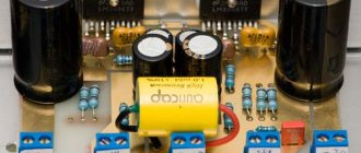
The appearance of the assembled printed circuit board of one UMZCH channel is shown in the abstract of the article.
The UMZCH connection in the device is made with a wire with a cross-section of 0.75 - 1 sq. mm. The mating part for the wires are 6.3 mm knife terminals (preferably insulated), designed for the specified wire cross-section. Crimping of knife terminals is performed with a special tool (Fig. 9). Pliers or a hammer will not provide the quality of connection achieved with special tools.
Rice. 9. Pliers for crimping terminals and contacts onto wires
↑ Setting up the amplifier
begin after carefully checking the correct installation.
Particular attention is paid to the correct installation of transistors, oxide capacitors and diodes, as well as the quality of soldering. To simplify setup, the slider of the trimming resistor R2 is set to the minimum resistance position, and the slider of the resistor R10 is set to half the nominal value. When turned on for the first time, the input jacks X1, X2 must be short-circuited and an equivalent load must be connected to the output. Operating modes should not differ from those indicated on the circuit diagram by more than 10%.
After a twenty-minute warm-up, resistor R10 sets the voltage at the symmetry point equal to half the supply voltage, and resistor R2 sets the output stage current to 60 mA, based on the voltage drop across resistors R11, R12 equal to 12 mV.
↑ Characteristics of its silicon counterpart
If instrumentation is available, the characteristics of the UMZCH are taken.
Characteristics of a simple UMZCH:
Supply voltage: 30 V; Maximum power with a load resistance of 4 Ohms: 20 W; Current consumption at maximum power, no more than: 1.0 A; Frequency range: 20 Hz…20 kHz (–0.5 dB); Harmonic distortion at 18 W output power: 0.03%; Voltage gain: 11.5 (21.2 dB); Sensitivity: 775 mV; Output resistance, no more than: 0.025 Ohm.
When connecting the amplifier to the sound reproduction path, it should be taken into account that it is inverting. It is necessary to take measures so that the path as a whole maintains the phase of the signal, i.e. was non-inverting. For example, take this fact into account by changing the polarity of connecting the speaker wires. However, the DACs of some players (for example, Pioneer BDP-170) invert the phase of the input signal, which, however, is not reflected in any way in the user manual.
↑ Buffer amplifier with level control based on a pseudo-push-pull repeater
In Fig.
Figure 2 shows a two-channel buffer amplifier with a level controller based on a pseudo-push-pull repeater, Fig. 1st century Here, instead of an emitter follower, a Szyklai circuit is used on transistors VT1, VT3 (VT5, VT4 in another channel). Fragment excluded. The full version is available to patrons and full members of the community.
Rice. 2. Schematic diagram of a buffer stage with a pseudo-push-pull repeater
The collector current of transistor VT1 (VT5) is set by resistor R5 (R11) and is I0=Ube/R5=0.2 mA, where Ube=0.66 V is the base-emitter voltage of transistor VT3 (VT4).
The current sources are made on transistors VT2 (VT6), the base circuits of the transistors are powered by a common parametric voltage stabilizer HL1, R8, C3 through resistors R7 and R9, respectively. The current source current is 10 mA.
The antiphase signal from resistor R4 (R10) through the separating capacitor C2 (C4) is supplied to the base of the current source transistor VT2 (VT6), which ensures the active operating mode of the repeater on both half-waves of the input signal.
↑ Characteristics
Supply voltage: 15 V;
Current consumption: 25 mA; Lower frequency level – 0.5 dB: 1 Hz; Output impedance: 0.5 ohm; Harmonic coefficient in the entire range of operating frequencies (20...20000 Hz) at Uin=1 V, Rн=620 Ohm: no more than 0.001%. Compare the technical characteristics of the pseudo push-pull repeater with the design from [2]. The pseudo-push-pull buffer has a six-fold lower output impedance, and non-linear distortion has decreased seventeen times!
Input resistance of the buffer stage Rin = 47 kOhm. If necessary, oxide capacitors C1 (C5) at the repeater inputs can be replaced with film capacitors, for example, with a capacity of 1 μF or 2.2 μF; at the same time, the lower frequency level - 3 dB will remain acceptable (3.4 Hz and 1.5 Hz, respectively).
↑ Details of the pseudo-push-pull repeater
VT1, VT2, VT5, VT6 – Transistor BC546 – 4 pcs., VT3, VT4 – Transistor BC556 – 2 pcs., HL1 – LED red d=3 mm BL-B51V1 – 1 pc., R1, R14 – Res.-0, 25-82 kOhm (Grey, red, orange, golden) – 2 pcs., R2, R15 – Res.-0.25-110 kOhm (Brown, brown, yellow, golden) – 2 pcs., R3, R4, R6, R10 , R12, R13 – Res.-0.25-100 Ohm (Brown, black, brown, golden) – 6 pcs., R5, R8, R11 – Res.-0.25-3.3 kOhm (Orange, orange, red, golden) – 3 pcs., R7, R9 – Res.-0.25-1.0 kOhm (Brown, black, red, gold) – 2 pcs., R16 – Res.-0.25-10 Ohm (Brown , black, black, gold) – 1 pc., C1, C5 – Cond. 10/25V 0511 +105°C– 2 pcs., C2, C3, C4 – Cond. 100/25V 0812 +105°С – 3 pcs., C6 – Cond. 1000/25V 1021 +105°C – 1 pc. Printed circuit board 54×54 mm – 1 pc.
↑ Repeater board
All parts of the pseudo-push-pull repeater are placed on a printed circuit board made of single-sided foil fiberglass 2 mm thick (Fig. 3).
Fragment excluded. The full version is available to patrons and full members of the community.
↑ Assembly and adjustment
First, fixed resistors and a jumper are installed, then, observing the polarity and pinout, capacitors, transistors and an LED.
The last thing to install on the board is a variable resistor. The setup comes down to checking the DC modes shown in Fig. 2. Adjustment of modes, if necessary, can be carried out by selecting resistors R1 (R14).
↑ Results
From the point of view of the requirements for an audio amplifier, we are dealing with an ideal structure
. Just one voltage amplification stage and a power amplifier based on complementary emitter followers have a single-pole frequency response with minimal delay in the transient process.
The advantages of the amplifier (one voltage amplification stage) are also its disadvantages. To obtain low nonlinear distortions, you need a large gain in the negative feedback loop, which is difficult to achieve with a single transistor connected in a common-emitter circuit.
Answering the question asked on the forum [4], I will say that UMZCHs based on a single-stage structure are close to tube sound
in the sense that, like a tube amplifier without negative feedback in class A,
they subjectively sound louder than “sophisticated” transistor amplifiers.
I can’t explain this fact with anything other than the better transient response of the amplifiers under consideration. Regardless of the element base used (silicon or germanium), the circuit is worthy of repetition, since the single-stage structure gives a head start to the mass of circuits that are operational amplifiers (differential stage, voltage amplifier, power amplifier).
The classical structure, even after half a century, is able to delight fans with clear, transparent sound with good technical characteristics and extreme simplicity of the circuit.
A known disadvantage of the circuit is its low input impedance, which must be taken into account when connecting signal sources to prevent overload.
↑ Possible options for implementing buffer cascades
are shown in Fig. 1a-d.
Rice. 1. Options for a buffer stage for a power amplifier: a) emitter follower, b) emitter follower with dynamic load, c) pseudo-push-pull emitter follower on transistors of the same structure, d) pseudo-push-pull emitter follower on complementary transistors
An emitter follower with a resistor in the emitter circuit (Fig. 1a) has the disadvantage that when the amplitude of the input signal increases, the limitation of one half-wave of the signal may occur earlier than the other [4].
During the positive half-wave of the input signal, the emitter current VT1 is divided between the resistances in the emitter Re and in the load Rн. During the negative half-wave, the current through Rн flows in the opposite direction.
To avoid limitation, the emitter current of transistor VT1 must always be greater than zero.
It is easy to show that the maximum peak amplitude of the output signal is related to the voltage at the emitter Uе and the load resistance Rн and emitter Re as follows: Uoutmax=UеRн/(Re+Rн).
For the circuit shown in Fig. 1a we get: Uoutmax = 7.5 0.62/(0.62+1.1) = 2.7 V.
The use of an active load in the emitter circuit allows you to eliminate the disadvantage of an emitter follower with a resistive load and further reduce distortion (Fig. 1 b). Part of the disadvantage of a simple emitter follower remains here: with a positive half-wave of the input signal, current is supplied not only to the load, but also to the current source.
Pseudo-push-pull repeaters can significantly reduce all types of distortion, as well as the output impedance. Here, a controlled current generator is used as an emitter load, forming a counter dynamic load for the second arm, Fig. 1st century
Shown in Fig. 1c diagram – transfer of a patent for a tube repeater from the forties of the last century to transistor circuitry [5].
Since transistor circuitry, unlike lamps, uses transistors of two types of conductivity, this circuit can be modified, resulting in a complementary pseudo-push-pull follower, Fig. 1 g. This scheme was successfully used by Vladimir ( vol2008
).
The low output impedance of the circuits shown in Fig. 1c and fig. 1 g, as well as less distortion compared to the circuits shown in Fig. 1a and fig. 1 b, have a positive effect on sound reproduction.
↑ Development of the presented scheme
Is it possible to improve the amplifier's performance?
It is possible if you increase the gain without feedback. I made the following improvements to the amplifier in the modeling system (Fig. 7): - I installed three output transistors instead of the two used; — replaced resistor R4 with a current source; — installed an additional emitter follower between the voltage amplifier and the output stage. The results are very encouraging, they allow you to test several circuits, but these will be completely different amplifiers.
↑ Good news - Datagor Project 008 “GeAmp1970” kit
We are pleased to inform you about the appearance of a new Datagor Project 008 “GeAmp1970” kit.
Amplifier based on germanium transistors. Building kit based on a wonderful circuit based on an amplifier from 1970 [1]. The kit was the result of long trials and discussions between Igor and I. The retro design has a tireless and transparent sound and will allow you not to lose the connection of times.
The project is easy to assemble and set up, allows for experimentation, uses a simple single-pole power supply and is great for beginners. Structurally, the amplifier parts are located on two printed circuit boards.
My friend Vladimir and I first assembled such an amplifier in the eighth grade of high school. He played wonderfully at one of the parties, which I still remember. In the future, quite often this design served as a “myth buster” for the high sound quality of many UMZCH circuits published in amateur radio literature. You assemble a complex amplifier with excellent characteristics, listen, and after a while this circuit with five transistors comes to hand, doubts begin, leading to further search...
↑ List of sources used
1. Ivanov V. Transformerless ULF // Radio, 1970, No. 2, p. 29, 30, 3rd cover page. 2. Levinzon G.L., Loginov A.V. High quality low frequency amplifier. – M.: Energy, 1977. – 120 p. 3. Tsikhiselli J. Germanium above all (AV Practice) // AudioVideo, 2003, No. 6 (//www.salonav.com/Praktika/6.2003/HTM/tranz.htm). 4. Classic amplifier circuit based on Ge germanium transistors - Forum on Datagor. 5. Pugachev I. Will the amplifier steal “virtual depth”? // Radio Amateur, 2000, No. 9, p. 3, 4. 6. Pugachev I.S. 50 years in service UMZCH // Radiomir, 2004, No. 8, p. 9 – 11. 7. Pugachev I. UMZCH with “virtual depth” on three transistors // Radiomir, 2008, No. 10, p. 3 – 5.
↑ List of sources mentioned
1. Mosyagin V., Silicon versus germanium in amplifiers of the same retro structure and a new germanium whale at the end // Journal of practical electronics "Datagor", 2016. 2. Mosyagin V., Input buffer and volume control for UMZCH // Journal of practical electronics “Datagor”, 2016. 3. Classic UMZCH (PowerAmplifier) circuit based on “Datagor” transistors // Forum on Datagor.
4. Rysin A. How to avoid signal limitation in an emitter follower with capacitive load decoupling // Radio pilot, 2015, April, p. 54 – 57. 5. White E. Improvements in or relating to thermionic valve amplifier circuit arrangements, British patent no. 564.250 (1940). 6. Petrov A. Pseudo-pull output stages of class A. // Radiohobby, 2014, No. 4, p. 57 – 61. Thank you for your attention!
