↑ Idea from Sanio - STK4231
About a year ago I bought two SANYO microcircuits - STK4231. I wanted to build an amplifier according to I. Korotkov’s article “320 W amplifier on the STK4231 chip”, published in RADIO magazine No. 11, 2005. Then problems arose with the board - I simply couldn’t do it well enough because I drew it with a marker (the board is visible in my article about photoresist) but there was no desire to redraw it in SPRINT LAYOUT. So the mikruhi remained in the box until recently.
I found an interesting article on the Internet by Finn Mikko Esala. So I assembled such an amplifier; I actually added a level indicator on the Samsung mikruha.
The amplifier is assembled according to a circuit close to the one in the datasheet. It is necessary to keep in mind that there are two modifications of STKashki – STK4231-II and STK4231-V. The differences are that STK4231-II pins 1, 2, 21, 22 are not used and the second one has a lower harmonic coefficient - 0.08%. The connection diagram for STK4231-V is slightly different - additional elements are simply connected as shown in the figure.
Add a link to a discussion of the article on the forum
RadioKot >Schemes >Audio >Amplifiers >
| Article tags: | Add a tag |
UMZCH on STK402-90
Author: Аleks-23 Published November 23, 2015 Created using KotoEd.
Hi all! I offer a version of a simple but very high-quality UMZCH based on the well-known SANYO STK402-090 microcircuit. One copy of which accidentally fell into my hands. The circuit includes the amplifier itself, speaker protection and a radiator cooling control circuit. The amplifier develops an output power of 2x50W into a 6 Ohm load. Supply voltage +/-25-40V.
Input signals come from the pre-amplifier (in my device it is a control unit on LM1036N) to connectors JP1, JP2. Relay KL101 output DC voltage protection relay. This protection also prevents clicks from occurring in the speakers during transients when the power is turned on and off. When turning on the power, a delay of 2-3 seconds occurs due to the charge of C104 through R105. When disconnected, the circuits highlighted with a red frame operate. The need to use these circuits is if the protection and UMZCH are powered from the same source. Then the presence of high-capacity filter capacitors will hold the KL101 relay when the power is turned off and the transient process will be heard in the speakers. If the protection is powered from a separate power supply, then the circuits highlighted by the frame do not need to be used. The filter capacitance in the protection power circuit is selected so that the KL101 relay turns off faster than the capacitors of the UMZCH power filter discharge. The IC201 chip and the VT201 transistor are used to assemble a cooling fan control circuit. The use of a powerful transistor is due to their large number in stock. If necessary, you can use other transistors, for example KT972, in this case resistors R205-10K, R206-2.2K. Fans from the ATX power supply are connected to connectors JP201, JP202. To eliminate interference, this circuit is powered from a separate power source, galvanically disconnected from the amplifier power supply. Here is the amplifier circuit board in two versions. In the second, there are no elements outlined in red.
Now about the details and setup. Only the radiator cooling fan control circuit needs adjustment. The desired temperature for turning on the fans is set by selecting resistor R203. Electrolytic capacitors in UMZCH are not lower than 50V, in protection circuits C101, C102, C104 35V C203 25V. The inductors are wound on a mandrel with a diameter of 3 mm, the winding length is 10 mm, 0.8 mm wire in three layers. Electromagnetic relay FINDER type 40.52 24VDC or other OMRON company for example. Instead of the UA741CN chip, you can use the KR140UD708. Thermistor from an ATX power supply with negative TCS. Instead of the STK402-090 chip, you can use STK402-070, STK402-120, STK402-100. Their parameters can be found in the attached datasheet.
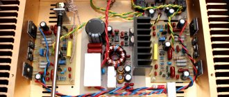
The photo shows the amplifier board assembled. Resistors R3, R14 were not used. The elements outlined in red are not installed in the protection circuit. The thermistor is pressed to the radiator with a piece of textolite through heat-conducting paste KPT-8. And one last thing. Unfortunately, the amplifier does not have protection against short-circuits in the load and overload. Therefore, during operation you need to be extremely careful to prevent short circuits in the speaker circuits. The amplifier is designed to work with 6 Ohm speakers, but using 4 Ohm speakers is quite possible. In this case, the power can be reduced to +/- 35V. I will post the power supply in the next article. Good luck!
Files:
datasheet stk402-090
All questions in the Forum.
| What do you think of this article? | Did this device work for you? | |
| 16 | 14 | 3 |
↑ Additions
Since this is still an STK, it sounds more powerful than the TDA, and to control the output power, I assembled a simple indicator on the KA2281 chip. Here's the diagram:
As you can understand from the diagram, when the level is low, the green LEDs light up, and as the signal level increases, the yellow, orange and red LEDs light up. This allows you to get rid of overloading the input of the microcircuit. The printed circuit board file is in the archive.
↑ Power supply
The power of the power supply should be taken 30-40% more than the output power of the amplifier. For such an amplifier, a transformer with a power of 400-450 watts is just right. I then used a transformer from the VENETS amplifier, which has two 32V windings and one 14V winding, not counting the network one. The 14V winding is used to power the level indicator and cooling fan. The voltage is stabilized by the ROLL.
The diode bridges of the UMZCH itself are removed from the printed circuit board and screwed to the base of the case. There is a printed circuit board for the 12V stabilizer.
Finished stereo amplifier board DX-401SK
Today is a little nostalgia post. Let's get acquainted with the finished audio power amplifier board based on the STK401-110 hybrid chip. Previously, before the widespread spread of compact class D amplifiers, Sanyo STK chips were found in almost all music centers and home movie receivers. STK are hybrid microcircuits made on unpackaged transistors using thick-film technology with laser adjustment of resistance values and SMD elements in a fairly large package. Something hybrid between a discrete (transistor) and a “chip” (TDA7294 or LM3886) amplifier. They have been produced since the 70s, there were many different modifications and types, but all of them were distinguished by high power, power supply from a bipolar source and an acceptable distortion factor. My first homemade amplifier (from whales) was STK404-140:
I was interested in “feeling” the Chinese implementation of the amplifier on STK. On banggood there are two options for boards with STK: the reviewed one (STK401-110) and also ready-made (“all in one”) on STK4132, but less powerful.
Let's start with the box, it's here with printing:
At the ends, connection diagram and technical specifications:
There is no additional packaging material inside:
DX-401SK board:
Peculiarities:
- Full radiator included
- Possibility of active cooling
- Rectifier on board
- Acoustic protection on relay
The board is powered by alternating current (with a midpoint) of 24-32 V, recommended 28-0-28 V. The board produces 70W+70W, THD = 0.4%, digests acoustics up to 3 Ohms. Board dimensions: 160x95 mm. There are 3 mounting holes for M4. Aluminum radiator dimensions: 140x50x40 mm, there are holes for installing a fan 80x80 mm. Dimensions STK 401: 75x50x8 mm. The filling of the microcircuit (ah, hybrid integrated circuit) is something like this:
PCB elements
Let's go through the components: 5 A diode bridge with the possibility of installing a radiator. Rectifier electrolytes FW(M) 6800 uF 50 V 2 pieces, not enough for me, I would put 10000 uF 50 V. Connectors for connecting power and output to CH3.96 speakers, the kind used in music centers. 4558D dual channel operational amplifier. IC for protecting acoustics uPC1237HA Input signal and fan on jst connector. Relay HR-CR323 24 V Documentation for STK401-110 Bottom board:
The layout resembles a datasheet. From the sides:
Let's move on to the tests.
To power this board, I bought a transformer from a music center (must follow the rules) MAX-KT65 or MAX-KJ610.
We cut off everything unnecessary:
The trans produces 29-0-29 V. Let’s first check how much power goes to the cooling “turntable”:
a bit much, you can reduce it with a DC-DC converter. Let's measure the output power on a sinusoidal signal:
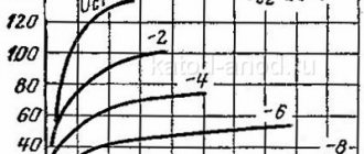
into a 4.5 ohm load you get 106 watts per channel! Let's look at the documentation:
Yes it seems. I have ~42 V power supply. Distortion is minimal at about 30 W of output power:
Heat Dissipation:
As a result of listening:
the board did not disappoint. It sounds bright and assertive. No hissing, no phonation even in such a “box” connection. The power is “horsepower”. True, it requires active cooling, my 42 V power supply is at its limit. You can assemble a vintage music center, which is what we will do in the following reviews.
Thank you for your attention. Enjoy the shopping!
The product was provided for writing a review by the store. The review was published in accordance with clause 18 of the Site Rules.
↑ Why “Clamshell Amplifier”? It will become clear soon! Design
I mounted it in a plastic case. The plastic is shock-resistant, plus you can carry the amplifier by the handle. Comfortable! That's right, a portable amp! Well, in case of repair it is convenient to service.